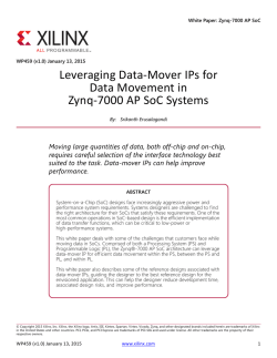
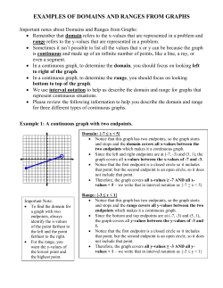
Discover How to Design a
Xilinx PCI Express Solution
with DMA Engine
Agenda
•
•
•
•
•
Introduction
Xilinx FPGA supporting PCI Express
Design with DMA Engine
Xilinx design aids
Summary
Introduction
• PCIe adoption has been
extremely rapid
– Est. PCI Express will
replace 80% of all
existing PCI ports by the
end of 2007
• All current new server
designs use PCIe
• Only PCIe expected to
be the dominant
protocol of choice
PCI Express Technology
• Differential low voltage
• Point-to-point dual simplex
• Packetized split transaction
• Embedded clock (8B10B)
• PIPE (Phy Interface PCI
Express)
– Gen 1 2.5GB
– 250MHz 8bit interface
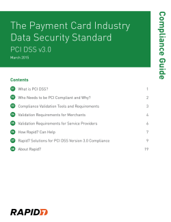
PCIe Topology
CPU
PCI Express
Graphics : 16X
Memory
ROOT COMPLEX
SWITCH
SWITCH
x2 End
Point
x1 END
POINT
SWITCH
PCI
Bridge
x8 END
POINT
Legacy
END
POINT
PCI
Virtex-5 PCIe Endpoint Block Applications
Can be open or
closed system
Xilinx PCI Leadership
• Industry’s First PCI core for FPGAs
• Industry’s First 64-bit, 133MHz PCI-X
Solution
• Industry’s First PCIe Solution
• Industry’s first FPGA with Integrated
block for PCI Express – Virtex-5
• Award winning Customer support
expertise
Xilinx FPGAs supporting PCIe
• Virtex™-5 FPGAs
–
–
–
–
–
Built-in Hard IP for PCIe
Integrated transceivers
High performance
Low power
1, 2, 4, 8 lane
• Spartan™-3 FPGAs
– 1 lane
– External PHY
– Low cost
PCIe Reference Designs
PCIe Reference Designs from Xilinx
Designs
XAPP
Contents (Board)
P2P bridge using PCIe block
XAPP 869
ML505
XAPP 859
Jungo WinDriver
ML555
XAPP 1052
Microsoft SDK
Performance Demo
ML555
PCIe to DDR2 Reference Design
PCIe “BMD” Reference Design
PCIe Reference Designs from Alliance Partners
Designs
Partner
Board/Device Support
IO control demo
Avnet
Spartan3 S3 PCIe SK:
PCIe to DMA
Northwest
Logic
ML555: V5LXT
PCIe to GE
CG CoreEl
ML505: V5LXT
PCIe to SDI/HDSDI
Image Proc Tech
IPT: V5LXT
PCI-SIG Compliance
• Virtex-5 - First FPGA solution to pass 1.1 compliance
– x1, x4 & x8 modes
• Added to Integrators list
– www.pcisig.com/developers/compliance_program/integrators_l
ist/pcie/
• Virtex-5 PCI Express Endpoint block passed the 3 SIG
Gold suites (Electrical, Configuration and Protocol)
• Passed interoperability
• FPGAs – Virtex-5 LXT, Virtex-5 SXT
• Boards – ML555, ML505, ML506, ML523
Smaller Device = Lower Cost
Area required to implement typical design
including x8 lane PCIe endpoint
Area (LUTs)
34,600
Virtex-5 LXT FPGAs (65nm)
User logic: 25,000 LUTs
25,100
Wrapper to interface to integrated
PCIe endpoint block: 100 LUTs
Nearest Competitor (90nm)
User logic: 25,000 LUTs
Area consumed to implement
PCIe soft core: 9,600 LUTs
5VLX30T
Choose a smaller,
less
-expensive device
less-expensive
2SGX60D
Conditions: Target Frequency = 200 MHz; Worst-case process; Tj=85В°C
Design: 25K LUTs, 17K Flip-Flops; 1 Mbit On-Chip RAM; 64 DSP Blocks, 128 2.5V I/Os
Tools: Based on Xilinx tool v8.2 and competitor tool v6.0.1
Virtex-5 Built-in Endpoint Block for PCIe
• Improve time-to-market
– Pre-verified highly complex IP
– Complete solution
– Included on PCI-SIG’s PCI Express Integrators List
• Logic area saving
– >90% area savings compared to the nearest competitor
– Easier timing closure
• High Performance
– Scalable solutions from x1 up to x8
• Low power solution
– >60% power savings compared to the nearest competitor
Design a Virtex-5 PCI Express
Application with DMA Engine
After this seminar, you can download a complete DMA design
example including ALL software source code and FPGA logic
source code as a freeware.
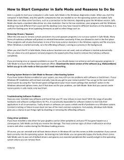
Programmable I/O vs. Bus
Mastering Endpoint DMA
Host PC
Programmable
I/O
Memory
Read
Memory
Write
CPU
CPU
MRd
ROOT COMPLEX
SYSTEM
MEMORY
Memory
Read
Memory
Write
MRd
CpID
SWITCH
Completions
Bus Mastering
Endpoint DMA
CpID
Completions
ENDPOINT
ENDPOINT
ENDPOINT
Virtex-5 PCI express add-in card
User application initiates bus mastering
DMA, Memory Read Request followed
by a Host sending Completion
DMA Engine for High
Throughput Applications
• DMA engine is a key element to achieve high bandwidth utilization
for a PCI Express application
– DMA can be optimized to best use bandwidth for specific application.
– As an example, using DMA engine in a PCI x1 link standard PC platform can
increase bandwidth by 2x~100x.
– DMA engine frees up CPU resources from data streaming, it helps to improve
the overall system performance.
• Typically, there are two types of DMA engines*
– “Common-buffer DMA”, also known as “continuous DMA”
– “Scatter/gather DMA”
– Many other DMA engine implementations derive from “Common-buffer DMA”
and “Scatter/gather DMA”
* According to document from http://www.microsoft.com/whdc/driver/kernel/dma.mspx
Design Process
Understand
Understand System
System
Requirements
Requirements
Configure
Configure PCIe
PCIe®®
Endpoint
Endpoint
Verify,
Verify, Simulate
Simulate &&
Implement
Implement
In System Validation
Board
Board level
level initial
initial test
test
Software
Software Driver
Driver and
and
Software
Software application
application
• System Architecture
• GUI in CoreGen
• Modelsim and ISE 9.1i
• Validation platform
– ML505/506/555 Evaluation board
– PCI scan software (e.g. pcitree)
– Driver software development suit
(e.g Jungo, or WDF)
Requirements for the DMA
Example design
•
•
System Requirements
–
–
–
–
–
Hardware Requirements
–
–
–
–
–
•
•
Bandwidth: x1
Power - < 1.0W for PCIe function
QoS: 1VC
Inter-operability
Hot-plug: yes for card slot
MPS: ASUS P5B-VM mother board with Intel 965 chipset
(or DELL GX280 with Intel 915 chipset )
Card Slot: default pre-emphasis and RX eq
BAR: 1 BAR (1MByte memory space)
Clocking:
•
•
Ref clock: 100MHz SSC comes over the slot
user clock: for x1 62.5MHz
Class Code: co-processor 0x0B400000
DMA:
–
–
Common-buffer DMA
Support bus master read/write DMA operation
Software Requirements
–
–
OS: Windows Driver
Simulation tools
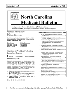
Virtex-5 PCI Express Solution
Block
Block
RAM
RAM
(Retry)
(Retry)
Block
Block
RAM
RAM
(Rx)
(Rx)
Endpoint Block Plus
Block RAM
Interface
Transaction
Layer
Interface
Data
Data Link
Link
Layer
Layer
Physical
Physical
Layer
Layer
User Application
Application
User
Transaction
Transaction
Layer
Layer
PL
PLLane
Lane
PL
PLLane
Lane
PL
Lane
PL Lane
PL
PLLane
Lane
PL
Lane
PL Lane
PL
PLLane
Lane
PL
PLLane
Lane
PL
PLLane
Lane
Transceiver
Interface
Configuration
Configuration and
and Capabilities
Capabilities Module
Module
Management
Interface
Wrapper
GTP(s))
GTP(s
GTP(s)
Block
Block
RAM
RAM
((Tx)
Tx)
Tx)
Power
Management
Interface
Miscellaneous
Miscellaneous Logic
Logic
(optional)
(optional)
Configuration
and Status
Interface
PCIe
Block
Clock and
Reset Interface
Clock
Clock and
and
Reset
Block
Reset Block
PCIe Layers Integrated into the
Virtex5 LXT/SXT
“Root Complex”
Software/ Driver
Transaction
“Endpoint”
Devices
Load/Store
Virtex-5 LXT/SXT
Software/
DMA engine
Transaction
PCIe block
Data Link
Physical
Frames
Data Link
Physical
• Layers including Transaction, Data Link and Physical, were integrated into PCIe block
• In PC system, users mainly focus on endpoint software/DMA engine design,
as well as software and driver design at root complex
GTP
Design Process
Understand
Understand System
System
Requirements
Requirements
Configure
Configure PCIe
PCIe®®
Endpoint
Endpoint
Verify,
Verify, Simulate
Simulate &&
Implement
Implement
In System Validation
Board
Board level
level initial
initial test
test
Software
Software Driver
Driver and
and
Software
Software application
application
• System Architecture
• GUI in CoreGen
• Modelsim and ISE 9.1i
• Validation platform
– ML505/506/555 Evaluation board
– PCI scan software (e.g. pcitree)
– Driver software development suit
(e.g Jungo, or WDF)
CoreGen Tool
• Supports all interfaces: PCIe-to-GTP & PCIe-to-BRAM
– Instantiates components
– Connects pins, and sets attributes
– Supports all user requirements
• GTP transceiver interface
– Choice of lane width: x1, x2, x4, x8
– Coregen hides GTP configuration complexities from the user
• BRAM interface
– Coregen instantiates the right number of BRAMs for each buffer
• Pipeline registers in the fabric must be added manually
• ECC support must be added manually
PCIe LogicCore in CoreGen
• Step by Step CoreGen flow can be found at Xilinx.com
– www.xilinx.com/products/boards/ml505/docs/ml505_pcie_x1_plus_design_creation.pdf
CoreGen Deliverables
• Parameterized Core Net-list
• Programmed Input Output (PIO) example design
• Customer Simulation Demonstration Test bench
– Verilog HDL simulation flow supported for PIO (VHDL planned)
– Includes complete Downstream PCIe port models (1 and 4 Lane)
– May be used to verify complex customer Endpoint designs
• Customer Implementation Demonstration
– Example UCFs delivered targeting ML555 board
– Complete implementation scripts delivered for PIO design
After CoreGen, you can build DMA engine on top of
the PIO example design
DMA Freeware example design
• How to get DMA Freeware example:
– Visit www.token2000.com for latest version.
http://www.token2000.com/DMA_Freeware_v1.2.zip
– DMA Freeware can be download from a Chinese BBS forum
http://www.edacn.net/bbs/forum-14-1.html
• After download
– You can compare the differences between “DMA engine
example design” with the coregen result which generated from
step-by-step guidance of
ml505_pcie_x1_plus_design_creation.pdf
– Read related documents to understand the DMA design code,
on top of PIO design.
Requirements for the DMA
Example design
•
•
System Requirements
–
–
–
–
–
Hardware Requirements
–
–
–
–
–
•
•
Bandwidth: x1
Power - < 1.0W for PCIe function
QoS: 1VC
Inter-operability
Hot-plug: yes for card slot
MPS: ASUS P5B-VM mother board with Intel 965 chipset
(or DELL GX280 with Intel 915 chipset )
Card Slot: default pre-emphasis and RX eq
BAR: 1 BAR (1MByte memory space)
Clocking:
•
•
Ref clock: 100MHz SSC comes over the slot
user clock: for x1 62.5MHz
Class Code: co-processor 0x0B400000
DMA:
–
–
Common-buffer DMA
Support bus master read/write DMA operation
Software Requirements
–
–
OS: Windows Driver
Simulation tools
Design Process
Understand
Understand System
System
Requirements
Requirements
Configure
Configure PCIe
PCIe®®
Endpoint
Endpoint
Verify,
Verify, Simulate
Simulate &&
Implement
Implement
In System Validation
Board
Board level
level initial
initial test
test
Software
Software Driver
Driver and
and
Software
Software application
application
• System Architecture
• GUI in CoreGen
• Modelsim and ISE 9.1i
• Validation platform
– ML505/506/555 Evaluation board
– PCI scan software (e.g. pcitree)
– Driver software development suit
(e.g Jungo, or WDF)
Virtex-5 PCIe Simulation
Link Partner
Downward facing
model
Test Bench
DUT
PCIe
Link
PCIe
Block
• SmartModel available for
simulation with
– Cadence “NC Verilog”
– Mentor “ModelSim”
– Synopsys “VCS”
• More details in UG341
User Guide document
Available in ISE9.1i SP3 IP3 or later
Config Space Simulation
•
•
•
•
•
•
•
•
•
•
•
•
•
•
Note: Model pcie_internal_1_1_swift: Model Vendor: `Xilinx'.
# Running test {sample_smoke_test0}......
#[
0] : System Reset Asserted...
#[
4995000] : System Reset De-asserted...
#[
8522100] : Transaction Reset Is De-asserted...
#[
80250100] : Transaction Link Is Up...
#[
80250100] : Expected Device/Vendor ID = 100010ee
#[
80250100] : Reading from PCI/PCI-Express Configuration Register 0x00
#[
80274000] : TSK_PARSE_FRAME on Transmit
#[
81994000] : TSK_PARSE_FRAME on Receive
#[
82674000] : TEST PASSED --- Device/Vendor ID 100010ee successfully
received
# ** Note: $finish : ../tests/sample_tests1.v(30)
# Time: 82674 ns Iteration: 9 Instance:
/boardx04/xilinx_pci_exp_4_lane_downstream_port/tx_usrapp
#
DMA Simulation
#[
#[
#[
#[
#[
#[
#[
………
#[
#[
#[
#[
#
#
#
#
#
#
#
#[
#[
#[
…….
#[
#[
#[
#[
#[
#[
#[
#[
0] : System Reset Asserted...
4995000] : System Reset De-asserted...
8522100] : Transaction Reset Is De-asserted...
80186100] : Transaction Link Is Up...
80186100] : Inspecting Core Configuration Space...
80282000] : TSK_PARSE_FRAME on Transmit
83578000] : TSK_PARSE_FRAME on Transmit
122714000] : TSK_PARSE_FRAME on Receive
123130000] : TSK_PARSE_FRAME on Transmit
125978000] : TSK_PARSE_FRAME on Receive
126330000] PCI EXPRESS BAR MEMORY/IO MAPPING PROCESS
BEGUN...
BAR 0: VALUE = 10000000 RANGE = fff00000 TYPE = MEM32
MAPPED
BAR 1: VALUE = 00000000 RANGE = 00000000 TYPE = DISABLED
BAR 2: VALUE = 00000000 RANGE = 00000000 TYPE = DISABLED
BAR 3: VALUE = 00000000 RANGE = 00000000 TYPE = DISABLED
BAR 4: VALUE = 00000000 RANGE = 00000000 TYPE = DISABLED
BAR 5: VALUE = 00000000 RANGE = 00000000 TYPE = DISABLED
EROM : VALUE = 10100001 RANGE = fff00001 TYPE = MEM32
MAPPED
126330000] : Setting Core Configuration Space...
126426000] : TSK_PARSE_FRAME on Transmit
129306000] : TSK_PARSE_FRAME on Receive
155706000] : TSK_PARSE_FRAME on Receive
184794000] : Set up for a Write DMA operation.
184794000] : Write the Write DMA starting address.
184890000] : TSK_PARSE_FRAME on Transmit
184890000] : Write the Write DMA length.
184986000] : TSK_PARSE_FRAME on Transmit
184986000] : Write the Write DMA TLP count.
185082000] : TSK_PARSE_FRAME on Transmit
#[
#[
#[
#[
#[
#[
#[
#[
#[
#[
#[
#[
…….
#[
#[
#[
185082000] : Write the Write DMA Data Pattern.
185178000] : TSK_PARSE_FRAME on Transmit
185178000] : Set up for a Read DMA operation.
185178000] : Write the Read DMA starting address.
185274000] : TSK_PARSE_FRAME on Transmit
185274000] : Write the Read DMA length.
185370000] : TSK_PARSE_FRAME on Transmit
185370000] : Write the Write DMA TLP count.
185466000] : TSK_PARSE_FRAME on Transmit
185466000] : Start the memory read and write DMA operation
simutaniously.
185562000] : TSK_PARSE_FRAME on Transmit
190298000] : TSK_PARSE_FRAME on Receive
202586000] : TSK_PARSE_FRAME on Receive
202586000] : Received Message with no Data --- Tag 0x00, message_type 0x4
202586000] : Interrupt received as expected. type[0x4],
code[0x20]
#[
202586000] : Write Interrupt ACK Register.
#[
202682000] : TSK_PARSE_FRAME on Transmit
#[
205786000] : TSK_PARSE_FRAME on Receive
#[
205786000] : Received Message with no Data --- Tag 0x00, message_type 0x4
#[
205786000] : Interrupt received as expected. type[0x4], code[0x24]
#[
205946000] : TSK_PARSE_FRAME on Receive
#[
205946000] : Received Message with no Data --- Tag 0x00, message_type 0x4
#[
205946000] : Interrupt received as expected. type[0x4], code[0x20]
#[
205946000] : Write Interrupt ACK Register.
#[
209146000] : Received Message with no Data --- Tag 0x00, message_type 0x4
#[
209146000] : Interrupt received as expected. type[0x4], code[0x24]
# ** Note: $finish : ../tests/BMD_rd_wr_tests.v(258)
# Time: 214138 ns Iteration: 10 Instance:
/boardx01/xilinx_pci_exp_1_lane_downstream_port/tx_usrapp
Design Process
Understand
Understand System
System
Requirements
Requirements
Configure
Configure PCIe
PCIe®®
Endpoint
Endpoint
Verify,
Verify, Simulate
Simulate &&
Implement
Implement
In System Validation
Board
Board level
level initial
initial test
test
Software
Software Driver
Driver and
and
Software
Software application
application
• System Architecture
• GUI in Coregen
• Modelsim and ISE 9.1i
• Validation platform
– ML505/506/555 Evaluation board
– PCI scan software (e.g. pcitree)
– Driver software development suit
(e.g Jungo, or WDF)
Board level initial test
• Requires a complete Endpoint
solution
– ML505/506/555 demo board
– DMA logic download files
– Software Utilities for PCI scan and
register read/write (e.g. PCI tree)
• Desktop, Workstation, Server,
Bridge and Switch equipment HW
for testing
– List some model of PC platform
• Dell SC430, Dell 1900, Dell
GX280
• ASUS P5B-VM , ASUS M2N-E
• Intel E7520
ML505/ML506/ML555 – Virtex-5 PCIe Development Platform
Use PCI Tree for Initial Test
• With PCI tree, you can try register read/write without software driver
• You can also work with software engineer, to physically allocate memory blocks,
and then trigger DMA operation by register read/write.
Design Process
Understand
Understand System
System
Requirements
Requirements
Configure
Configure PCIe
PCIe®®
Endpoint
Endpoint
Verify,
Verify, Simulate
Simulate &&
Implement
Implement
In System Validation
Board
Board level
level initial
initial test
test
Software
Software Driver
Driver and
and
Software
Software application
application
• System Architecture
• GUI in CoreGen
• Modelsim and ISE 9.1i
• Validation platform
– ML505/506/555 Evaluation board
– PCI scan software (e.g. pcitree)
– Driver software development suit
(e.g Jungo, or WDF)
Try out DMA Example Software
• In system test with the DMA example software
• All driver and application software source codes and executables
are provided as is.
• As a freeware, you can modify by yourself or contact the designer
for more details.
Performance Example(1)
ML505 PCIe x1 on Intel 915G Mainstream PC
• Read
– 128DW *2000 Reads test, the
performance is 172MBps
• Write
– In 32DW *2000 writes test, the
performance is 212MBps
Typically, PCI32bit @ 33Mhz about
80MBps, PCI64bit @ 66Mhz about
250MBps in commercial products.
PCIe x1 show better typical
performance than PCI32bit @ 33Mhz,
also close to PCI64bit @ 66Mhz.
Performance Example(2)
ML555 PCIe x4 on Dell Precision 690 workstation
• Read
– 128DW *2000 Reads test, the
performance is 738MBps
• Write
– In 32DW *2000 writes test, the
performance is 842MBps
Typically, 100Mhz PCI-X may reach
350MBps in commercial products.
PCIe x4 show better typical
performance than 100Mhz PCI-X.
System Considerations
• Power: <100mW per GTP lane, < 450 mW for PCIe
Block
• Latency: 400ns
• Bandwidth: effective BW is system dependent (RC & OS)
• SI: TX pre-emphasis and RX eq
• Drivers: Jungo Linux and Window
• Compliance & Interoperability: PCI-SIG integrators list
Requirements for the DMA
Example design
•
•
System Requirements
–
–
–
–
–
Hardware Requirements
–
–
–
–
–
•
•
Bandwidth: x1
Power - < 1.0W for PCIe function
QoS: 1VC
Inter-operability
Hot-plug: yes for card slot
MPS: ASUS P5B-VM mother board with Intel 965 chipset
(or DELL GX280 with Intel 915 chipset )
Card Slot: default pre-emphasis and RX eq
BAR: 1 BAR (1MByte memory space)
Clocking:
•
•
Ref clock: 100MHz SSC comes over the slot
user clock: for x1 62.5MHz
Class Code: co-processor 0x0B400000
DMA:
–
–
Common-buffer DMA
Support bus master read/write DMA operation
Software Requirements
–
–
OS: Windows Driver
Simulation tools
Xilinx Development Kits for PCI Express
PCIe Development Kit for Virtex-5
Available now - $2200
• Development Kits include:
– Hardware: ML555 board & download
–
–
–
–
cable
ISE Foundation eval DVD
Reference Designs
Documentation
Quick Start Guide
PCIe Development Kit for Spartan-3
Available now - $349
• Development Kits include:
– Spartan 3 Board for PCI Express
• Soft PCIe IP & external Philips PIPE
PHY
– Design resources
• Application Notes
• Software design tools
• Interoperability list
Summary
• PCIe is becoming the interconnect of choice
• Xilinx offers PCIe solutions requirements for highperformance and low-cost
• Xilinx offers complete kits to accelerate development for
PCIe
• A complete DMA engine design including HDL source
code, Windows driver and application software can be
downloaded as a example.
Getting Started
• http://www.xilinx.com/cn/pciexpress
• Design Resources
•
•
•
•
•
•
Technical Documentation & Application Notes
IP LogiCOREs & Design guidelines
Characterization reports
Xilinx courses
Software tools
Design Services
• Evaluate Xilinx PCI express build-in IPcore, use the
DMA Freeware example as a reference
• Contact Xilinx Distributor FAE or Xilinx FAE for more
support
Thank You
Description of DMA
V5 LXT Bus Mastering DMA
• Northwest Logic DMA Reference Design and Driver IP
– Simulation evaluation available
– Support for Xilinx V5LXT Development Kit for PCIe
– V5 LXT BLK+ x1, x4 and x8 deliverables
– DDR2,SRAM Controller, source code,
– Device Drivers (Windows / Linux)
– Design services
http://www.xilinx.com/member/pci_exp_kit_ref/index.htm
DMA Reference Design from
Northwest Logic
http://www.nwlogic.com/docs/PCI_Express_Reference_Design.pdf
Driver Development Kit
WinDriver – from Jungo, Inc
• Complete PCIe Design Kit for Xilinx FPGAs, enables
– Rapid creation of applications
– Faster device driver code-development
– Reduce development time by providing
• Kernel mode performance
• Higher level of abstraction
http://www.xilinx.com/member/pci_exp_kit_ref/index.htm
© Copyright 2026 Paperzz