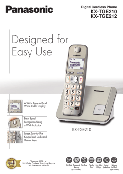
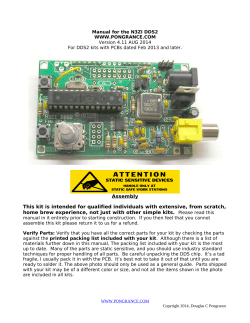
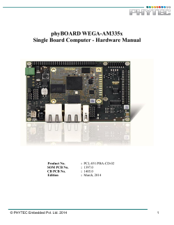
How to control a HD44780-based Character-LCD
http://ouwehand.net/~peter/lcd/lcd.shtml
How to control a HD44780-based Character-LCD
The Industry Standard Character LCD
Visitor # (unknown)
В© 1995-2004 Peter Ouwehand.
Last updated on 2005-01-21
TOC | General info | 8051 example | PIC example | Misc. examples | Manuf./Distrib. | Home | Sign
Guestbook | View Guestbook
Table Of Contents
0. Table Of Contents
1. General
1.1. Disclaimer
1.2. Usage
1.3. Purpose
2. HD44780-based LCD modules
2.1. Pin assignment
2.2. Instruction set
2.3. Visible DDRAM addresses
2.3.1. 1-line displays
2.3.2. 2-line displays
2.3.3. 4-line displays
2.4. Interfacing
2.4.1. 8-bit interface
2.4.2. 4-bit interface
2.5. Character set
2.6. Related pages
3. 8051 example
3.1. Basic control software
3.1.1. Requirements / features
3.1.2. Global declarations
3.1.2.1. Register declarations
3.1.2.2. Literal declarations
3.1.2.3. Procedure declarations / library interface
3.1.3. Code
3.1.3.1. LCD initialisation
3.1.3.2. Busy flag
3.1.3.3. Clear display
3.1.3.4. Cursor home
3.1.3.5. Entry mode
3.1.3.6. Display mode
3.1.3.7. Set character generator RAM address
3.1.3.8. Set display data RAM address
3.1.3.9. Get address counter contents
3.1.3.10. Write character
3.2. Advanced control software
3.2.1. Requirements / features
3.2.2. Global declarations
3.2.2.1. Procedure declarations / library interface
3.2.3. Code
3.2.3.1. User defined characters
3.2.3.2. Set cursor position
3.2.3.3. Write character
1 of 2
2/11/2005 5:16 AM
How to control a HD44780-based Character-LCD
http://ouwehand.net/~peter/lcd/lcd.shtml
3.2.3.4. Write string
...
3.3. Availability
3.4. Target hardware
3.4.1. Controller
3.4.2. Interface
3.4.2.1. LCD interface
3.4.2.2. Address decoder example
3.5. Development environment
3.5.1. Software
3.5.2. Hardware
4. PIC example
4.1. Basic control software
4.1.1. Requirements / features
4.1.2. Global declarations
4.1.2.1. Register declarations
4.1.2.2. Literal declarations
4.1.2.3. Procedure declarations / library interface
4.1.3. Code
4.1.3.1. LCD initialisation
4.1.3.2. Busy flag
4.1.3.3. Clear display
4.1.3.4. Cursor home
4.1.3.5. Entry mode
4.1.3.6. Display mode
4.1.3.7. Set character generator RAM address
4.1.3.8. Set display data RAM address
4.1.3.9. Get address counter contents
4.1.3.10. Write character
4.1.3.11. Write command
4.1.3.12. Delay loops
4.2. Advanced control software
4.2.1. User defined characters
...
4.3. Availability
4.4. Target hardware
4.4.1 Controller
4.4.2 Interface
4.5. Development environment
4.5.1. Software
4.5.2. Hardware
5. Miscellaneous examples
5.1. PIC16C54 using only 3 lines
5.2. ATMEL AT90S2313-10PI C-demo
5.3. Variant on PIC16C54 using only 3 lines
5.4. Other information sources
6. Manufacturers and Distributors
6.1. Europe
6.2. North America
6.3. Asia
6.4. Australia
6.5. South America
6.6. Africa
TOC | General info | 8051 example | PIC example | Misc. examples | Manuf./Distrib. | Home | Sign
Guestbook | View Guestbook
2 of 2
2/11/2005 5:16 AM
How to control a HD44780-based Character-LCD
http://ouwehand.net/~peter/lcd/lcd0.shtml#general
How to control a HD44780-based Character-LCD
The Industry Standard Character LCD
Visitor # (unknown)
В© 1995-2004 Peter Ouwehand.
Last updated on 2005-01-21
TOC | General info | 8051 example | PIC example | Misc. examples | Manuf./Distrib. | Home | Sign Guestbook | View Guestbook
General info and code-examples
TOC
1. General
1.1. Disclaimer
1.2. Usage
1.3. Purpose
2. HD44780-based LCD modules
2.1. Pin assignment
2.2. Instruction set
2.3. Visible DDRAM addresses
2.3.1. 1-line displays
2.3.2. 2-line displays
2.3.3. 4-line displays
2.4. Interfacing
2.4.1. 8-bit interface
2.4.2. 4-bit interface
2.5. Character set
2.6. Related pages
1. General
TOC
1.1. Disclaimer
THIS DOCUMENT IS PROVIDED TO THE USER ''AS IS''. Etc.etc.
All information in this document is to the best of my knowledge.
The 8051 PL/M51 software is used in applications using 2*16, 2*20, 4*20 and 2*40 LC-Displays.
The PIC ASM software is used in applications using 2*20, 4*20 and 2*40 LC-Displays.
So there should be no risk, but there's still Murphy.
TOC
1.2. Usage
Tell me about your applications.
Send a postcard
TOC
1.3. Purpose
Uuuhm..
TOC
2. HD44780-based LCD modules
Data from HITACHI LIQUID CRYSTAL CHARACTER DISPLAY MODULE and OPTREX DOT MATRIX LCD MODULE databooks.
TOC
2.1. Pin assignment
The pin assignment shown in Table 2.1. is the industry standard for character LCD-modules with a maximum of 80 characters.
The pin assignment shown in Table 2.2. is the industry standard for character LCD-modules with more than 80 characters.
To be sure always check the manufacturers datasheet!
To locate pin 1 on a module check the manufacturers datasheet!
Table 2.1., Pin assignment for <= 80 character displays
Pin number Symbol Level I/O
Function
1
Vss
- Power supply (GND)
2
Vcc
- Power supply (+5V)
3
Vee
- Contrast adjust
1 of 5
2/11/2005 5:17 AM
How to control a HD44780-based Character-LCD
http://ouwehand.net/~peter/lcd/lcd0.shtml#general
Pin number Symbol Level I/O
Function
4
RS
0/1
I 0 = Instruction input
1 = Data input
5
R/W
0/1
I 0 = Write to LCD module
1 = Read from LCD module
6
E
1, 1->0 I Enable signal
7
DB0
0/1 I/O Data bus line 0 (LSB)
8
DB1
0/1 I/O Data bus line 1
9
DB2
0/1 I/O Data bus line 2
10
DB3
0/1 I/O Data bus line 3
11
DB4
0/1 I/O Data bus line 4
12
DB5
0/1 I/O Data bus line 5
13
DB6
0/1 I/O Data bus line 6
14
DB7
0/1 I/O Data bus line 7 (MSB)
Table 2.2., Pin assignment for > 80 character displays
Pin number Symbol Level I/O
Function
1
DB7
0/1 I/O Data bus line 7 (MSB)
2
DB6
0/1 I/O Data bus line 6
3
DB5
0/1 I/O Data bus line 5
4
DB4
0/1 I/O Data bus line 4
5
DB3
0/1 I/O Data bus line 3
6
DB2
0/1 I/O Data bus line 2
7
DB1
0/1 I/O Data bus line 1
8
DB0
0/1 I/O Data bus line 0 (LSB)
9
E1
1, 1->0 I Enable signal for row 0 and 1 (1stcontroller)
10
R/W
0/1
I 0 = Write to LCD module
1 = Read from LCD module
11
RS
0/1
I 0 = Instruction input
1 = Data input
12
Vee
- Contrast adjust
13
Vss
- Power supply (GND)
14
Vcc
- Power supply (+5V)
15
E2
1, 1->0 I Enable signal for row 2 and 3 (2ndcontroller)
16
n.c.
TOC
2.2. Instruction set
Table 2.3. HD44780 instruction set
Code
Execution
Description
time**
RS R/W DB7 DB6 DB5 DB4 DB3 DB2 DB1 DB0
Clear display
0 0
0
0
0
0
0
0
0
1 Clears display and returns cursor to the home position (address 0).
1.64mS
Cursor home
0 0
0
0
0
0
0
0
1
* Returns cursor to home position (address 0). Also returns display
1.64mS
being shifted to the original position. DDRAM contents remains
unchanged.
Entry mode set
0 0
0
0
0
0
0
1 I/D S Sets cursor move direction (I/D), specifies to shift the display (S).
40uS
These operations are performed during data read/write.
Display On/Off control 0 0
0
0
0
0
1
D C
B Sets On/Off of all display (D), cursor On/Off (C) and blink of cursor
40uS
position character (B).
Cursor/display shift
0 0
0
0
0
1 S/C R/L *
* Sets cursor-move or display-shift (S/C), shift direction (R/L). DDRAM
40uS
contents remains unchanged.
Function set
0 0
0
0
1 DL N
F
*
* Sets interface data length (DL), number of display line (N) and
40uS
character font(F).
Set CGRAM address 0 0
0
1
CGRAM address
Sets the CGRAM address. CGRAM data is sent and received after
40uS
this setting.
Set DDRAM address 0 0
1
DDRAM address
Sets the DDRAM address. DDRAM data is sent and received after
40uS
this setting.
Read busy-flag and
0 1 BF
CGRAM / DDRAM address
Reads Busy-flag (BF) indicating internal operation is being
0uS
address counter
performed and reads CGRAM or DDRAM address counter contents
(depending on previous instruction).
Write to CGRAM or
1 0
write data
Writes data to CGRAM or DDRAM.
40uS
DDRAM
Read from CGRAM or 1 1
read data
Reads data from CGRAM or DDRAM.
40uS
DDRAM
Remarks:
- DDRAM = Display Data RAM.
- CGRAM = Character Generator RAM.
- DDRAM address corresponds to cursor position.
- * = Don't care.
- ** = Based on Fosc = 250kHz.
Instruction
2 of 5
2/11/2005 5:17 AM
How to control a HD44780-based Character-LCD
http://ouwehand.net/~peter/lcd/lcd0.shtml#general
Table 2.4. Bit names
Bit name
Setting / Status
I/D
0 = Decrement cursor position 1 = Increment cursor position
S
0 = No display shift
1 = Display shift
D
0 = Display off
1 = Display on
C
0 = Cursor off
1 = Cursor on
B
0 = Cursor blink off
1 = Cursor blink on
S/C 0 = Move cursor
1 = Shift display
R/L
0 = Shift left
1 = Shift right
DL
0 = 4-bit interface
1 = 8-bit interface
N
0 = 1/8 or 1/11 Duty (1 line) 1 = 1/16 Duty (2 lines)
F
0 = 5x7 dots
1 = 5x10 dots
BF
0 = Can accept instruction
1 = Internal operation in progress
TOC
2.3. Visible DDRAM addresses
TOC
2.3.1. 1-line displays
Shown after reset (with N=0).
Table 2.5. DDRAM address usage for a 1-line LCD
Display size
1*8
1*16
1*20
1*24
1*32
1*40
Visible
Character positions DDRAM addresses
00..07
0x00..0x07
00..15
0x00..0x0F [1] [2] [3] [4]
00..19
0x00..0x13
00..23
0x00..0x17
00..31
0x00..0x1F
00..39
0x00..0x27
[1] Peter Bozzay:
Found DDRAM addresses 0x00..0x07 + 0x40..0x47 to be functional for a 1*16 display size.
Make/model: not mentioned / SC1601AS*B.
[2] Hendrik Abma:
Found DDRAM addresses 0x00..0x07 + 0x40..0x47 to be functional for a 1*16 display size.
Make/model: Samtron / KP-03.
[3] Luigi Candurro:
Found DDRAM addresses 0x00..0x07 + 0x40..0x47 to be functional for a 1*16 display size.
Make/model: Crystal Clear Technology / CMC116-01.
[4] Thierry Giorgetti:
Found DDRAM addresses 0x00..0x07 + 0x40..0x47 to be functional for a 1*16 display size.
Make/model: Xiamen Ocular / GDM1601c (Local copy available as zipped file, approx 278kB).
TOC
2.3.2. 2-line displays
Shown after reset (with N=1).
Table 2.6. DDRAM address usage for a 2-line LCD
Display size
2*16
2*20
2*24
2*32
2*40
Visible
Character positions
DDRAM addresses
00..15
0x00..0x0F + 0x40..0x4F [1]
00..19
0x00..0x13 + 0x40..0x53
00..23
0x00..0x17 + 0x40..0x57
00..31
0x00..0x1F + 0x40..0x5F
00..39
0x00..0x27 + 0x40..0x67
[1] Author:
According to their datasheets DDRAM addresses 0x80..0x8F + 0xC0..0xCF are used.
Make/model: Emerging Display Technologies / EW162G0YMY (Local copy available as zipped file, approx 85kB).
Make/model: Mitsutech / EW162G0YMY (Local copy available as zipped file, approx 86kB).
TOC
2.3.3. 4-line displays
Shown after reset (with N=1).
3 of 5
2/11/2005 5:17 AM
How to control a HD44780-based Character-LCD
http://ouwehand.net/~peter/lcd/lcd0.shtml#general
Table 2.7. DDRAM address usage for a 4-line LCD
Display size
4*16
4*20
4*40
Visible
Character positions
00..15
00..19
DDRAM addresses
0x00..0x0F + 0x40..0x4F + 0x14..0x23 + 0x54..0x63 [1] [2]
0x00..0x13 + 0x40..0x53 + 0x14..0x27 + 0x54..0x67
(00..39) on 1st controller and
(0x00..0x27 + 0x40..0x67) on 1st controller and
(0x00..0x27 + 0x40..0x67) on 2nd controller
nd
(00..39) on 2
controller
[1] Rick Mann:
Found DDRAM addresses 0x00..0x0F + 0x40..0x4F + 0x10..0x1F + 0x50..0x5F to be functional for a 4*16 display size.
Make/model: Optrex / DMC16433.
Author:
This matches with the information mentioned in Dmcman_full.pdf paragraph 1.7.6.4. Local copy available as zipped file, approx 176kB.
[2] Tushar Rane:
Found DDRAM addresses 0x00..0x0F + 0x40..0x4F + 0x10..0x1F + 0x50..0x5F to be functional for a 4*16 display size.
Make/model: not mentioned / not mentioned.
TOC
2.4. Interfacing
TOC
2.4.1. 8-bit interface
Example of busy flag testing using an 8-bit interface.
TOC
2.4.2. 4-bit interface
Example of busy flag testing using a 4-bit interface.
Example of data transfer using a 4-bit interface.
4 of 5
2/11/2005 5:17 AM
How to control a HD44780-based Character-LCD
http://ouwehand.net/~peter/lcd/lcd0.shtml#general
TOC
2.5. Character set
Characterset for 5x7 dot font
TOC
2.6. Related pages
Private sites:
- Fil's FAQ-Link-In Corner: LCD Technology FAQ
- Fil's FAQ-Link-In Corner: HD44780-based LCD
- LCD Module to PC Interfacing Example
- HD44780-based LCD Modules
Commercial sites:
- LCD Intro
- HANTRONIX, Inc. Home Page
- Shelly, Inc. - LCD Engineering Application Notes
TOC
TOC | General info | 8051 example | PIC example | Misc. examples | Manuf./Distrib. | Home | Sign Guestbook | View Guestbook
5 of 5
2/11/2005 5:17 AM
How to control a HD44780-based Character-LCD
http://ouwehand.net/~peter/lcd/lcd2.shtml#PIC_example
How to control a HD44780-based Character-LCD
The Industry Standard Character LCD
Visitor # (unknown)
В© 1995-2004 Peter Ouwehand.
Last updated on 2005-01-21
TOC | General info | 8051 example | PIC example | Misc. examples | Manuf./Distrib. | Home | Sign Guestbook | View
Guestbook
Code examples for PIC16C84
TOC
4. PIC example
4.1. Basic control software
4.1.1. Requirements / features
4.1.2. Global declarations
4.1.2.1. Register declarations
4.1.2.2. Literal declarations
4.1.2.3. Procedure declarations / library interface
4.1.3. Code
4.1.3.1. LCD initialisation
4.1.3.2. Busy flag
4.1.3.3. Clear display
4.1.3.4. Cursor home
4.1.3.5. Entry mode
4.1.3.6. Display mode
4.1.3.7. Set character generator RAM address
4.1.3.8. Set display data RAM address
4.1.3.9. Get address counter contents
4.1.3.10. Write character
4.1.3.11. Write command
4.1.3.12. Delay loops
4.2. Advanced control software
4.2.1. User defined characters
...
4.3. Availability
4.4. Target hardware
4.4.1 Controller
4.4.2 Interface
4.5. Development environment
4.5.1. Software
4.5.2. Hardware
4. PIC example
TOC
4.1. Basic control software
Microchip's AN587 was used as a basis for this code.
WARNING:
Microchip's AN587 has major errors in the read from LCD code sequences.
The routines on this page use the correct read from LCD code sequences.
TOC
4.1.1. Requirements / features
- HD44780-based (industry-standard) character-LCD, all software in this chapter is based on it's instruction-set.
- PIC16C84 running on a 4MHz crystal, some code is based on this frequency.
1 of 8
2/11/2005 5:18 AM
How to control a HD44780-based Character-LCD
http://ouwehand.net/~peter/lcd/lcd2.shtml#PIC_example
- 8-bit interface between microcontroller and LCD-module.
TOC
4.1.2. Global declarations
To get things working.
TOC
4.1.2.1. Register declarations
Purpose:
- Tells MPASM which ports and registers (files) to use.
Code:
LCD_DATA
LCD_DATA_TRIS
LCD_CTRL
EQU
EQU
EQU
PORTB
TRISB
PORTA
; LCD data lines interface
LCD_TEMP
EQU
0x020
; LCD subroutines internal use
DELAY
X_DELAY
EQU
EQU
0x023
0x024
; Used in DELAYxxx routines
; Used in X_DELAYxxx routines
; LCD control lines interface
TOC
4.1.2.2. Literal declarations
Purpose:
- Literal declarations (Equates) used in the code.
Code:
; PORTA control bits
LCD_E
EQU
LCD_RW
EQU
LCD_RS
EQU
2
1
0
; LCD Enable control line
; LCD Read/Write control line
; LCD Register-Select control line
TOC
4.1.2.3. Procedure declarations / library interface
Since MPLIB and MPLINK are not yet available, no declarations are needed.
TOC
4.1.3. Code
TOC
4.1.3.1. LCD initialisation
Purpose:
- LCD initialisiation code to be executed after power-up (i.e.: before any other subroutin
- Should be modified to your needs (i.e. display type, cursor on/off, etc.)
Code:
LCDINIT
2 of 8
CLRF
LCD_CTRL
MOVLW
CALL
0x01E
X_DELAY500
; Busy-flag is not yet valid
; ALL PORT output should output Low.
; power-up delay
; 30 * 0.5mS = 15mS
; Busy Flag should be valid from here
2/11/2005 5:18 AM
How to control a HD44780-based Character-LCD
MOVLW
CALL
MOVLW
CALL
CALL
MOVLW
CALL
MOVLW
CALL
RETURN
0x038
LCDPUTCMD
0x000
LCDDMODE
LCDCLEAR
0x004
LCDDMODE
0x002
LCDEMODE
http://ouwehand.net/~peter/lcd/lcd2.shtml#PIC_example
; 8-bit-interface, 2-lines
; disp.off, curs.off, no-blink
; disp.on, curs.off
; auto-inc (shift-cursor)
TOC
4.1.3.2. Busy flag
Purpose:
- Tests if the LCD is busy. Returns when LCD busy-flag is inactive.
Code:
LCDBUSY
BSF
MOVLW
MOVWF
BCF
BCF
BSF
BSF
MOVF
BCF
ANDLW
BTFSS
GOTO
LCDNOTBUSY
BCF
BSF
MOVLW
MOVWF
BCF
RETURN
STATUS,RP0
0x0FF
LCD_DATA_TRIS
STATUS, RP0
LCD_CTRL, LCD_RS
LCD_CTRL, LCD_RW
LCD_CTRL, LCD_E
; Select Register page 1
; Set PORTB for input
LCD_DATA, W
LCD_CTRL, LCD_E
0x80
STATUS, Z
LCDBUSY
; Read busy flag + DDram address
; LCD E-line Low
; Check Busy flag, High = Busy
LCD_CTRL, LCD_RW
STATUS, RP0
0x000
LCD_DATA_TRIS
STATUS, RP0
;
;
;
;
Select Register page 0
Set LCD for command mode
Setup to read busy flag
LCD E-line High
; Select Register page 1
; Set PORTB for output
; Select Register page 0
TOC
4.1.3.3. Clear display
Purpose:
- Clears display and returns cursor to home position (upper-left corner).
Code:
LCDCLEAR
MOVLW
CALL
RETURN
0x001
LCDPUTCMD
TOC
4.1.3.4. Cursor home
Purpose:
- Returns cursor to home position.
- Returns display to original position (when shifted).
Code:
3 of 8
2/11/2005 5:18 AM
How to control a HD44780-based Character-LCD
LCDHOME
MOVLW
CALL
RETURN
http://ouwehand.net/~peter/lcd/lcd2.shtml#PIC_example
0x002
LCDPUTCMD
TOC
4.1.3.5. Entry mode
Purpose:
- Sets entry mode of the LCD
- Required entry mode must be set in W
b0
: 0 = no display shift, 1 = display shift
b1
: 0 = auto-decrement, 1 = auto-increment
b2-b7 : don't care
Code:
LCDEMODE
ANDLW
IORLW
CALL
RETURN
0x003
0x004
LCDPUTCMD
; Strip upper bits
; Function set
TOC
4.1.3.6. Display mode
Purpose:
- Sets display control
- Required entry mode must
b0
: 0 = cursor blink
b1
: 0 = cursor off,
b2
: 0 = display off,
b3-b7 : don't care
be set in W
off, 1 = cursor blink on (if b1 = 1)
1 = cursor on
1 = display on (display data remains in DD-RAM)
Code:
LCDDMODE
ANDLW
IORLW
CALL
RETURN
0x007
0x008
LCDPUTCMD
; Strip upper bits
; Function set
TOC
4.1.3.7. Set character generator RAM address
Purpose:
- Sets the Character-Generator-RAM address. CGRAM data is read/written after this setting.
- Required CGRAM address must be set in W
b0-5 : required CGRAM address
b6-7 : don't care
Code:
LCDSCGA
ANDLW
IORLW
CALL
RETURN
0x03F
0x040
LCDPUTCMD
; Strip upper bits
; Function set
TOC
4 of 8
2/11/2005 5:18 AM
How to control a HD44780-based Character-LCD
http://ouwehand.net/~peter/lcd/lcd2.shtml#PIC_example
4.1.3.8. Set display data RAM address
Purpose:
- Sets the Display-Data-RAM address. DDRAM data is read/written after this setting.
- Required entry mode must be set in W
b0-6 : required DDRAM address
b7
: don't care
Code:
LCDSDDA
IORLW
CALL
RETURN
0x080
LCDPUTCMD
; Function set
TOC
4.1.3.9. Get address counter contents
Purpose:
- Returns address counter contents, used for both DDRAM and CGRAM.
- RAM address is returned in W
Code:
LCDGADDR
BSF
MOVLW
MOVWF
BCF
BCF
BSF
BSF
MOVF
BCF
ANDLW
BCF
BSF
MOVLW
MOVWF
BCF
RETURN
STATUS,RP0
0x0FF
LCD_DATA_TRIS
STATUS, RP0
LCD_CTRL, LCD_RS
LCD_CTRL, LCD_RW
LCD_CTRL, LCD_E
LCD_DATA, W
LCD_CTRL, LCD_E
0x07F
LCD_CTRL, LCD_RW
STATUS, RP0
0x000
LCD_DATA_TRIS
STATUS, RP0
; Select Register page 1
; Set PORTB for input
;
;
;
;
;
;
;
Select Register page 0
Set LCD for command mode
Setup to read busy flag
LCD E-line High
Read busy flag + RAM address
LCD E-line Low
Strip upper bit
; Select Register page 1
; Set PORTB for output
; Select Register page 0
TOC
4.1.3.10. Write character
Purpose:
- Sends character to LCD
- Required character must be in W
Code:
LCDPUTCHAR
MOVWF
CALL
BCF
BSF
BSF
MOVF
MOVWF
BCF
RETURN
LCD_TEMP
LCDBUSY
LCD_CTRL,
LCD_CTRL,
LCD_CTRL,
LCD_TEMP,
LCD_DATA
LCD_CTRL,
LCD_RW
LCD_RS
LCD_E
W
LCD_E
;
;
;
;
;
Character to send is in W
Wait for LCD to be ready
Set LCD in read mode
Set LCD in data mode
LCD E-line High
; Send data to LCD
; LCD E-line Low
TOC
5 of 8
2/11/2005 5:18 AM
How to control a HD44780-based Character-LCD
http://ouwehand.net/~peter/lcd/lcd2.shtml#PIC_example
4.1.3.11. Write command
Purpose:
- Sends command to LCD
- Required command must be in W
Code:
LCDPUTCMD
MOVWF
CALL
BCF
BCF
BSF
MOVF
MOVWF
BCF
RETURN
LCD_TEMP
LCDBUSY
LCD_CTRL,
LCD_CTRL,
LCD_CTRL,
LCD_TEMP,
LCD_DATA
LCD_CTRL,
LCD_RW
LCD_RS
LCD_E
W
LCD_E
;
;
;
;
;
Command to send is in W
Wait for LCD to be ready
Set LCD in read mode
Set LCD in command mode
LCD E-line High
; Send data to LCD
; LCD E-line Low
TOC
4.1.3.12. Delay loops
Purpose:
- Used in LCDINIT subroutine
- Required delay factor must be in W
(Could be coded more efficient, but this approach gives more flexibility)
Code:
;***********************************
DELAY500
MOVLW
D'165'
;
MOVWF
DELAY
;
DELAY500_LOOP
DECFSZ
DELAY, F
;
GOTO
DELAY500_LOOP
;
DELAY500_END
RETURN
;
a 500uS delay @ 4MHz X-tal
;***********************************
X_DELAY500
MOVWF
X_DELAY
;
X_DELAY500_LOOP
CALL
DELAY500
;
DECFSZ
X_DELAY, F
;
GOTO
X_DELAY500_LOOP
;
X_DELAY500_END
RETURN
;
a delay of 'W' * 500mS
+1
+2
1 cycle
1 cycle
step1
step2
1 cycle
2 cycles
+3
2 cycles
+1
1 cycle
step1
step2
step3
wait 500uSec
1 cycle
2 cycles
+2
2 cycles
TOC
4.2. Advanced control software
TOC
4.2.1. User defined characters
Purpose:
After several requests a quick explanation on how to implement
user-defined characters:
First you'll need to make a pixel definition for the characters
you want to use. This is the pixel definition for an underlined
'0' (char code 0x30) based on a 5x7 dots character definition:
6 of 8
2/11/2005 5:18 AM
How to control a HD44780-based Character-LCD
http://ouwehand.net/~peter/lcd/lcd2.shtml#PIC_example
|
bits
| byte
row | 76543210 | value
-----------------------000 |
xxx
| 0x0E
001 |
x
x | 0x11
010 |
x xx | 0x13
011 |
x x x | 0x15
100 |
xx x | 0x19
101 |
x
x | 0x11
110 |
xxx
| 0x0E
111 |
xxxxx | 0x1F
The byte values need to be loaded into CGRAM address 00cccrrr
(binary), where:
- ccc = user-defined character number (0...7)
- rrr = row number of the user defined character (0...7)
Once that's done you can write character codes 0...7 to the
desired LCD character position, just like you do with
'normal' characters.
User-defined character definitions may be changed 'on-the-fly'.
While defining a 5x7 dots character:
- Character code bits (DDRAM) 2..0 correspond to CGRAM address bits 5..3
(i.e. 8 possible user defined characters).
While defining a 5x10 dots character:
- Character code bits (DDRAM) 2..1 correspond to CGRAM address bits 5..4
(i.e. 4 possible user defined characters).
It's best to switch off the cursor while writing to CGRAM.
Code:
(More detailed code may be published some day)
TOC
4.3. Availability
LCD-PIC.ZIP (17,796 bytes): an example using some of the above subroutines (all subroutines are included).
Source is coded for a 4*20 LCD, adjust it to your needs!
Shows the following screen on a 4*20 LCD:
---------------------|This is on line : 0|
|This is on line : 1|
|This is on line : 2|
|This is on line : 3|
---------------------Picture of the above (296K).
Shows the following screen on a 2*40 LCD:
----------------------------------------|This is on line : 0This is on line : 2|
|This is on line : 1This is on line : 3|
------------------------------------------
Shows the following screen on a 2*20 LCD:
---------------------|This is on line : 0|
|This is on line : 1|
7 of 8
2/11/2005 5:18 AM
How to control a HD44780-based Character-LCD
http://ouwehand.net/~peter/lcd/lcd2.shtml#PIC_example
---------------------TOC
4.4. Used hardware
TOC
4.4.1 Controller
- A PIC16C84 is used to control the LCD.
- 8-bit data interface between controller and LCD.
TOC
4.4.2 Interface
TOC
4.5. Development environment
TOC
4.5.1. Software
- Assembler: MPASM V1.30
- Programmer software: PICSTART 16B1 V5.00.00
TOC
4.5.2. Hardware
- Programmer PICSTART 16B1 (firmware V2.00)
TOC
TOC | General info | 8051 example | PIC example | Misc. examples | Manuf./Distrib. | Home | Sign Guestbook | View
Guestbook
8 of 8
2/11/2005 5:18 AM
How to control a HD44780-based Character-LCD
http://ouwehand.net/~peter/lcd/lcd_examp.shtml#start
How to control a HD44780-based Character-LCD
The Industry Standard Character LCD
Visitor # (unknown)
В© 1995-2004 Peter Ouwehand.
Last updated on 2005-01-22
TOC | General info | 8051 example | PIC example | Misc. examples | Manuf./Distrib. | Home | Sign Guestbook |
View Guestbook
Miscellaneous examples
TOC
5. Miscellaneous examples
5.1. PIC16C54 using only 3 lines
5.2. ATMEL AT90S2313-10PI C-demo
5.3. Variant on PIC16C54 using only 3 lines
5.4. Other information sources
5. Miscellaneous examples
TOC
5.1. PIC16C54 using only 3 lines
This example is donated by Marc Simons.
If you have any questions/comments please send e-mail to [email protected].
1 of 5
2/11/2005 5:18 AM
How to control a HD44780-based Character-LCD
http://ouwehand.net/~peter/lcd/lcd_examp.shtml#start
Brief description:
Pins RB0, RB1 and RB2 are used for controlling AND driving text to the LCD display. Most of the time the PIC's are
sufficient enough for most applications, except when it comes to more I/O. This simply cannot be expanded, except
when you go to the BIG GUYS like the PIC16C74 etc. where I have done some applications with too. Observe the
schematics: An PIC16C54 is the heart of the whole thing. It drives the HEF4094 CMOS serial2parallel converter.
This gives us the databus towards the LCD display. Since the HEF4094 strobe is activated at the rising edge, and
the LCD display on the falling edge, these can be shared. So, on the rising edge the 4094 spits out it's new byte,
and on the falling edge the LCD reads it in. By the way, this concept cannot read out info from the LCD display.
(Personal opinion: It is useless anyway!) Now the hard part comes: How to derive 'text' from 'commands'?? The
LCD has a pin for it: The RS-pin. When it is clear, commands are accepted. when set, text is accepted. How is it
solved?
Before I spit out a character to the HEF4094, I set the clock for 500uSec. Resistor R1 will load capacitor C5. Then, I
spit the text character towards the 4094 as soon as possible. Therefore the capacitor simply does not have the time
to discharge: The LCD will accept it as text. For commands it is the same, however, of course the other way around:
The capacitor must be discharged. T1 forms an emitter follower to buffer the R/C network. The reason for this is that
2 of 5
2/11/2005 5:18 AM
How to control a HD44780-based Character-LCD
http://ouwehand.net/~peter/lcd/lcd_examp.shtml#start
the LCD RS input is an TTL input, so without proper buffering it will not work.
The code contains a few basic routines to handle the LCD display. The switch that I added is purely for fun: To be
able to toggle rotation of the text. I used an 16 characters / 2 lines LCD display from an old security keypad. (Go to a
surplus electronics store, they always have some!)
P.S. Any suggestions for good code from YOUR side are always welcome! Best Regards from [email protected],
your PIC Scueezer Weezel!
MSIMONS.ZIP (27,140 bytes) includes the schematics, source code and include file needed for this example.
TOC
5.2. ATMEL AT90S2313-10PI C-demo
This demo is donated by Jon Wackley (VE3JTN).
If you have any questions/comments please send e-mail to [email protected].
Brief description:
Chip:
ATMEL AT90S2313-10PI
Clock:
9.420 MHz
Compiler: avr-gcc
Written by: Jon Wackley (VE3JTN)
Date:
November 3rd 2002
Availability: ATMEL_AT90S2313-10PI.zip (2,559 bytes) which contains the C-source
Table 5.1. Hardware
interface
ATMEL PIN
PD0(2)
PD1(3)
PD6(11)
PB0(12)
PB1(13)
PB2(14)
PB3(15)
PB4(16)
PB5(17)
PB6(18)
PB7(19)
LCD PIN
RS(4)
R/W(5)
E(6)
D0(7)
D1(8)
D2(9)
D3(10)
D4(11)
D5(12)
D6(13)
D7(14)
TOC
5.3. Variant on PIC16C54 using only 3 lines
This example is donated by Stefan Heinzmann.
If you have any questions/comments please send e-mail to Stefan Heinzmann.
3 of 5
2/11/2005 5:18 AM
How to control a HD44780-based Character-LCD
http://ouwehand.net/~peter/lcd/lcd_examp.shtml#start
Brief description:
I just came across the schematics for driving an LCD module with just 3 lines on the PIC
(http://home.iae.nl/users/pouweha/lcd/lcd.shtml). I just wanted to show you an even simpler (and slightly cheaper)
way:
- Replace the HEF4094D with a plain 8-bit shift register like the 74HC164 (it will be slightly cheaper). It has no STR
input, so the PIC's RB3 just connects to the LCD module's EN signal.
- Connect RB1 to the RS signal of the LCD module, and to the two data inputs of the 74HC164. After having shifted
out a byte into the 74HC164, you can put the state of the RS signal on this line.
You don't need a transistor and such, and the timing isn't critical.
You operate it like this:
With EN inactive, you shift out a byte into the shift register in the same way as you did before. This byte defines
what's on the DB0-7 signals. Of course, DB0-7 will wiggle while you're shifting, but the LCD will not care as long as
EN is inactive. Then, with EN still inactive, you put the state of RS on the PIC's RB1 pin, but you don't toggle the
clock line (RB0). Then, you pulse the EN line (RB2) to make the LCD module accept the byte.
It should also be possible to use this technique with a hardware SPI port, which is available in some PICs (or other
controllers).
Cheers Stefan
TOC
5.4. Other information sources
america.renesas.com/products/supportdocs/hd44780.pdf (Local copy available as zipped file, approx 318kB)
www.repairfaq.org/filipg/LINK/F_LCD_menu.html
www.repairfaq.org/filipg/LINK/F_Tech_LCD.html
members.optushome.com.au/donmck/dtait/testlcd.c
4 of 5
2/11/2005 5:18 AM
How to control a HD44780-based Character-LCD
http://ouwehand.net/~peter/lcd/lcd_examp.shtml#start
www.rentron.com/Myke1.htm
www.oopic.com/lcd.htm
ee.cleversoul.com/lcd_project.html
ee.cleversoul.com/hotsheet_opto.html#lcds
TOC
TOC | General info | 8051 example | PIC example | Misc. examples | Manuf./Distrib. | Home | Sign Guestbook |
View Guestbook
5 of 5
2/11/2005 5:18 AM
© Copyright 2026 Paperzz