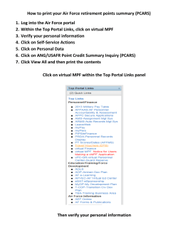
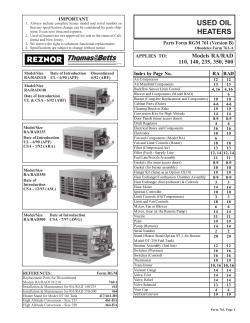
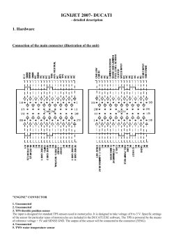
U S E R M A N UA L electric basin heater I N S TA L L AT I O N – O P E R AT I O N – M A I N T E N A N C E M92-1322C I S S UE D 0 7 / 2014 R E A D A N D U N D E R S TAN D TH I S M AN UAL P R I O R TO O P E RATI N G OR S E RVI CI N G T H I S PR O D U CT. receiving and inspection The heater package is shipped directly from the vendor. 1. Check all parts for any damage in transit. The carrier is responsible for the condition of the heater package upon arrival. If damage is apparent, note the freight bill accordingly. This will support your claim with the freight carrier. 2. Check the nameplate on the enclosure and verify that the heaters and the control panel are rated for the correct voltage. 3. Check the watt rating on each element and verify the sum of all elements is equal to the KW rating as ordered. 4. The control panel is nameplated for the maximum amperage that the panel can safely control and may be equal to or greater than the actual amperage required for your heater package. See Installation Instructions on page 5 to calculate amperage required. 3 introduction The purpose of a basin heater is to prevent water freezing in the cooling tower basin during periods of shutdown or standby operation. The heater system is sized according to tower model and location to give maximum protection against water freezing in the cold water basin. This heating system is not intended to protect the tower fill and other components from icing. Refer to Marley Technical Bulletin # H-002 "Operating Cooling Towers in Freezing Weather." Contact your Marley Sales Representative for a copy of this publication. The Marley basin heater system is manufactured by INDEECO, a leader in immersion heating equipment. The system is referred to as a "heater package" and consists of immersion heaters, a control panel and combination temperature / liquid level sensor with a 12'-0" cable length. The basic control panel contains a contactor(s) of sufficient capacity for the heater elements selected. In addition the panel contains a transformer to reduce line voltage to 24VAC for panel control power, and a solid state relay card to detect low temperature and low water conditions. The panel enclosure is rated NEMA 4X (liquid tight, noncorrosive) and the sensor cable is UL outdoor rated. The sensor probe is stainless steel with 1⁄2" NPT threads and a PVC bulkhead fitting for installation in the cold water basin. The panel may control more than one heating element, up to its nameplate KW rating for the voltage and phase stated. In addition to the components of the basic panel described above, available options are fusing, circuit breakers or disconnect switches. The circuit diagram located on the inside of the panel cover will indicate the panel configuration. The following defined terms are used throughout this manual to bring attention to the presence of hazards of various risk levels, or to important information concerning the life of the product. Warning Indicates presence of a hazard which can cause severe personal injury, death or substantial property damage if ignored. Caution Indicates presence of a hazard which will or can cause personal injury or property damage if ignored. Note 4 Indicates special instructions on installation, operation or maintenance which are important but not related to personal injury hazards. installation Note For detailed information concerning installation, refer to the heater installation drawing provided with the cooling tower. Heater Element Install the heater element(s) in the depressed area of the cold water basin near the outlet. Provide clearance of 7⁄8" or more above the floor. A single centrally located heater can protect up to 300 square feet of basin surface area from ice damage. To protect larger surface areas, position several heaters so they protect equal areas. For multicell towers, no more than two cells may be protected by a single heater package. For three or more cells additional heater packages are necessary. Caution Table 1 The heater should never operate out of the water. It would become extremely hot (1500°F) and destroy the heater element and/or ignite nearby combustible materials. As a precaution and to prevent fires when the clearance between any part of a heater element and combustible materials is less than 10", install a sheet metal shield to reflect and dissipate the heat. The shield must not contact the heater element and should extend beyond the heater element in all directions as shown in Table 1. Heater Clearance inches 1 2 4 6 8 10 Shield Extension inches 10 9 7 4 2 0 Heater Supports Install metal supports for the heater element where necessary to keep the unsupported length under 30". The number of supports required is as shown in Table 2. Table 2 Heater Kilowatts 1-9 12-18 Number of Supports None 1 5 installation Control Panel The control panel is suitable for outdoor mounting, and may be mounted on the tower, but not inside the tower. Wire the heaters to the panel. Wire the panel to the branch circuit supplying power to the heater. The field supplied branch circuit disconnect switch and the branch circuit protective device (fusing or circuit breaker) shall be sized in accordance with the NEC/CEC rules for actual load. The total heater load can be calculated as shown below. If the heater control panel is furnished with an optional disconnect, installation of the panel in relationship to the heater element shall be in accordance with the NEC/CEC rules. The main incoming conduit hub and the main power termination points are sized for total nameplate KW and voltage. The actual load for a particular installation may be less. Either compute the actual load on the heater control panel to determine the sum total KW of all the heaters connected to it or use the nameplate rating to determine the wire size required. To calculate amp draw for a particular installation use the following formulas: KW x 1000 = Amperage for Single Phase Applications Voltage or KW x 1000 1.7312 x Voltage Caution = Amperage for Three Phase Applications Should water be drained, either intentionally or accidentally, from the basin, the basin heater MUST be checked manually to insure the power source to the heating element is OFF. Although equipped with a low liquid level sensor probe, contaminants on or around the probe may cause false readings allowing the element to remain energized under low or no water conditions. Do not re-energize the unit until the sensor probe is fully submerged in water. IF THE UNIT IS ENERGIZED WHILE THE SENSOR PROBE IS NOT FULLY SUBMERGED IN WATER, COMBUSTION/FIRE MAY RESULT, WHICH COULD DAMAGE OR DESTROY THE TOWER AND MAY CAUSE DAMAGE TO PERSONS OR PROPERTY NEARBY. 6 installation Temperature / Water Level Sensor Assembly Warning This basin heater package is equipped with a combination temperature/liquid level sensor and may have a thermal cutoff switch. Both are safety devices that must not be altered or changed in any manner. Disabling either safety feature may result in combustion and/or fire, which could cause damage or destroy the tower and may cause damage to persons or property nearby. Failure of one or both safety devices requires that the control panel be de-energize and tag circuit out for maintenance. Do not re-energize the unit until all safety devices are fully operational in accordance with manufacturer's specifications. The sensor assembly is factory installed to the control panel. Do not attempt to lengthen or shorten the cord. Sensor assemblies with various lengths up to 99'-0" are available and may be specified at the time of purchase for additional cost. Install the sensor probe in the cold water basin at least 1" above the highest point of the heater element and at least 6" away from the heater. The probe should be installed in the coldest part of the basin for maximum protection. It should extend into the open basin a minimum of 4". A 1⁄2" NPT PVC bulkhead fitting is provided on the sensor for mounting through the basin wall. Provide an 15⁄8" clearance hole through the basin wall. Remove the nut from the bulkhead fitting and insert the sensor probe through the hole. Hand tighten the mounting nut onto the fitting, holding the bulkhead fitting to avoid twisting the cord. Lightly tighten the nut. 7 operation Operating Instructions To operate the heater system, visually check that the water level is above the sensor probe before energizing the power supply. The temperature control is preset at 45°F. The system will not energize unless the water level is above the sensor probe and the temperature of the water is below the 45° set point. The solid state relay card located in the control panel has a green and a red LED—see Figure 1. In a "ready" condition, with water level above the sensor probe and temperature above 45°F both these LEDs will be off. If the red LED is illuminated this indicates a low water condition and the heaters will not operate. If the green LED is illuminated the heater elements are on. RED GREEN 120 24 240 COM NC NO SH T1 T2 G1 G2 CT SOLID STATE RELAY CARD N Figure 1 RED PROBE BLK RED BLK SHIELD BASIN LED INDICATORS Table 3 Caution RedGreen OFF OFF Ready, No Demand ON OFF Low Water Level OFF ON Heater On Should water be drained, either intentionally or accidentally, from the basin, the basin heater MUST be checked manually to insure the power source to the heating element is OFF. Although equipped with a low liquid level sensor probe, contaminants on or around the probe may cause false readings allowing the element to remain energized under low or no water conditions. Do not re-energize the unit until the sensor probe is fully submerged in water. IF THE UNIT IS ENERGIZED WHILE THE SENSOR PROBE IS NOT FULLY SUBMERGED IN WATER, COMBUSTION/FIRE MAY RESULT, WHICH COULD DAMAGE OR DESTROY THE TOWER AND MAY CAUSE DAMAGE TO PERSONS OR PROPERTY NEARBY. 8 operation Testing above Freezing Temperatures Under normal operating conditions the heaters will be turned on at a water temperature between 40° and 45°F, and turned off when the water temperature exceeds 45°F. For testing the system at temperatures above 45°F there are two methods as follows: Method A 1. Disconnect power to the control panel using standard lockout procedure for safety. 2. Remove the panel cover 3. Remove the sensor wires connected to terminals T1 and T2 on the relay circuit board. SH T1 T2 G1 G2 COM NC NO RED GREEN 120 N CT SOLID STATE RELAY CARD 24 240 Figure 2 RED PROBE BLK RED BLK SHIELD RESISTOR BASIN 4. Connect a 1.5K ohm resistor (included in panel) across T1 and T2 terminals—see Figure 2. 5. Replace panel cover and verify probe is submerged in tower basin water. 6. With panel cover in place turn on power supply to the system. An audible CLICK should be heard as the contactor engages. If this does not happen, refer to the Troubleshooting section of this manual. 7. If the system tests OK turn off power, remove the panel cover and remove the resistor. Replace sensor wires T1 and T2 and replace the cover. Turn system on. ➠9 operation Method B 1. Disconnect power to the heater control panel using standard lockout procedures for safety. 2. Drain basin until the water level is below the probe allowing removal of the probe. Make sure water still covers the heater elements. 3. Place the probe in a container of ice water making sure both metal parts of the probe are submerged but not the cord. 4. Energize the heater control panel. Allow 5 min. for the probe temperature to stabilize. 5. An audible CLICK should be heard as the heater contactor engages. If this does not happen, refer to the Troubleshooting section. 10 operation Deicing If the temperature/water level sensor assembly becomes encased in ice the heaters will not operate. Ice provides inadequate conductivity for the sensor probe to detect operational water level. To operate heaters in this situation and melt the ice follow these procedures. 1. Disconnect power to the control panel using standard lockout procedures for safety. 2. Remove the panel cover. 3. I nstall a jumper wire between relay terminals G1 and G2—see Figure 3. JUMPER RED GREEN COM NC NO SH T1 T2 G1 G2 CT 24 240 120 N Figure 3 SOLID STATE RELAY CARD RED PROBE BLK RED BLK SHIELD BASIN 4. Replace panel cover. 5. Energize the system and listen for contactor closing. 6. Operate the system until ice is melted around the sensor probe. 7. After ice is melted, de-energize the system, remove the jumper, check all connections and place the system back in operation. Caution Do not leave the heating system unattended during this procedure. There is no low water protection with this jumper in place. 11 troubleshooting Caution Please refer to the Caution statement on Page 6 and the Warning statement on Page 7 of this manual before performing the following Troubleshooting procedures. If the system fails to operate, check the following: 1. Check water temperature. Systems will turn on between 40° and 45°F and turn off above 45°F. 2. Check water level. Water must completely cover the sensor probe. 3. Make sure the sensor is not encased in ice. See Deicing procedure. Caution The following checks should be made by a qualified electrician. 4. Remove panel cover and check incoming electrical power for proper voltage. Make sure all phases are present. Correct as required. 5. If water level is adequate, temperature is 40°F or lower and power is present, observe the LEDs on the relay circuit board. The red LED indicates low water level or ice around the probe and the green LED indicates the heaters are energized. A. If the red LED is on and the sensor probe is submerged in water—no ice—this indicates the sensor probe is defective. Confirm by disconnecting power and placing a jumper across terminals G1 and G2—see Figure 3. Reconnect power. If the red LED is now off and the green LED is on, the system is now operating. Replace sensor probe. B. If the green LED is on and the heaters are not operating, the problem is either the contactor, the relay circuit board or the heater elements. To determine which, observe the panel while power is disconnected and reconnected. – If the contactor operates with an audible CLICK and no heat results the heater element is defective. Check voltage at the heater side of the contactor to confirm voltage is present. Check each line with a clamp-on amp meter. If voltage is present and no current is flowing, this indicates the element is defective and must be replaced. As an additional check, disconnect power, remove wires from the contactor and check the element with an ohm meter for measurable resistance. 12 troubleshooting – If the contactor does not operate, check voltage across terminal N on the circuit board and NO on the relay mounted on the circuit board —21-29 volt required. If voltage is present across the coil—N to NO— the contactor coil is defective and the contactor must be replaced. If voltage is not present, the circuit board relay is defective and the circuit board must be replaced. C. If the green LED is off and the red LED is also off the problem is either the circuit board, the sensor probe, or the transformer. To determine which check as follows: – Disconnect power and remove wires T1 and T2 from the circuit board. Replace with the 1.5K ohm resistor provided. See Figure 2. If the system now works, the sensor probe is defective and must be replaced. If the system does not work, go to step 2. – Reconnect power and take a voltage reading across N and 24/240 on the circuit board—21-29 volts required. If proper voltage is not present the transformer is defective and must be replaced. If proper voltage is present go to step 3. – Take a voltage reading across N and NO—21-29 volts required. If proper voltage is not present, replace circuit board. 6. The sensor assembly can be checked for accuracy in the following manner. Remove wires T1 and T2 from the circuit board and measure ohm readings across these wires. Measure the water temperature that the probe is being exposed to. Compare with the following values. Table 4 Temp °F ohms 0 4273 10 3126 20 2312 32 1633 40 1305 45 1138 60 765 75 525 85 412 13 parts list 1 2 24 240 120 N CT COM NC NO 3 RED GREEN SH T1 T2 G1 G2 4 5 Replacement Parts 1 Transformer 120V/24V...........................................................B52465D Transformer 208V/24V...........................................................A79270D Transformer 240V/24V...........................................................B91566D Transformer 480V/24V...........................................................B09608D Transformer 600V/24V...........................................................B62553D 2 Contactor 50 amp, 600V, 24 volt coil................................C32328D 3 Solid State Relay Card..........................................................A79269D 4 Sensor Probe with 12' cord..................................................A81137D Sensor Probe with 22' cord..................................................B07688D –contact Marley Sales Rep for other cord lengths 5 Heater Element—contact Marley for specific heater elements Call your Marley Sales Representative for replacement parts. For the location of your Marley Sales Representative call 913 664 7400 or check the web at spxcooling.com. 14 electric basin heater U S E R M A N UA L SPX COOLING TECHNOLOGIES, INC. 7401 W 129 ST OVERLAND PARK, KANSAS 66213 USA P: 913 664 7400 F: 913 664 7439 [email protected] spxcooling.com In the interest of technological progress, all products are subject to design and/or material change without notice. ISSUED 07/2014 M92-1322C COPYRIGHT © 2014 SPX Corporation
© Copyright 2026 Paperzz