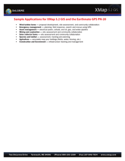
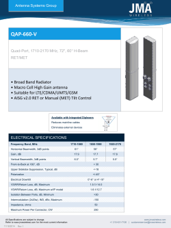
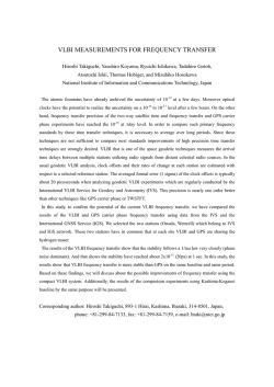
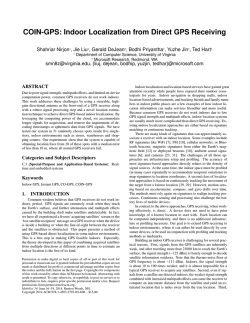
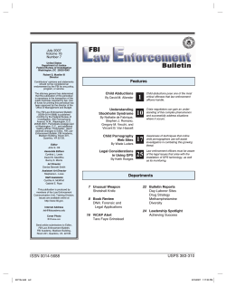
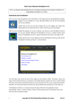
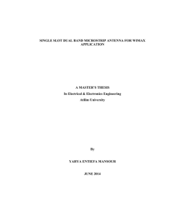
GNS TC6000GN–EM1 EvalKit for TI microcontroller boards manual confidential information manual The GNS TC6000GN-EM1 Evaluation Board has been designed to support developers during design-in of the TC6000GN-P1 GPS stand alone module solution. The examples are shown as block diagrams to explain the approaches. Reference Layouts are included whenever needed at the GNS forum Link: www.forum.gns-gmbh.com . . GNS Global Navigation Systems GmbH Adenauerstrasse 18 D – 52146 WГјrselen Germany www.gns-gmbh.com [email protected] 1 В© GNS-GmbH 2012 V 1.1, March 14th 2014 GNS TC6000GN–EM1 EvalKit for TI microcontroller boards manual confidential information manual Introduction Together with a Texas Instruments MSP-EXP430F5438, MSP-EXP430F5529 or Stellaris LM3S9B96 Cortex M3 EVB (all not included) and a dedicated test firmware, the TC6000GN-EM1 evaluation board provides a plug-and-play solution to demonstrate the performance and functionality of the TC6000GN-P1 GPS module. For technical specification, please refer to the TC6000GN-P1 datasheet. For application information and GPS antenna layout implementation, the TC6000GN Design Guide and “GPS Antenna Connection” Design Guide are available. Applications were two GPS antennas should be used, a special GPS antenna evaluation board “GPS SPDT switch” can be ordered. The specific documents and reference layout in Gerber-file format are available for download at http://www.forum.gns-gmbh.com/ . This document describes the TC6000GN-EM1 EvalKit hardware in detail. Since the test FW is provided in source code, it can be easily used to start a GPS development on it. As a further feature, the test FW routes all GPS data (NMEA) directly to the USB port, which can be connected to a PC. TC6000GN-EM1 connected to MSP-EXP430F5529 Status : GOOD FIX Sats in Fix : 5 50В° 48.32477' N 6В°. 09.15039' E 2 В© GNS-GmbH 2012 V 1.1, March 14th 2014 GNS TC6000GN–EM1 EvalKit for TI microcontroller boards manual confidential information manual Index 1 2 3 4 5 Description of the TC6000GN-EM1 EvalKit Hardware ........................................................... 4 Package Content .................................................................................................................. 4 TC6000GN-EM1 Board Layout .............................................................................................. 5 TC6000GN-EM1 Board Block Diagram .................................................................................. 6 TC6000GN-EM1 on Texas Instruments Experimental Boards ................................................ 7 5.1 TI's MSP EXP430F5438 board. ........................................................................................ 7 5.2 Getting started …. ......................................................................................................... 7 5.3 Using TI's MSP-EXP430F5529 board ................................................................................ 8 5.4 Update TC6000GN-P1 module using the MSP-EXP430F5529 board ...................................... 9 6 TC6000GN-EM1 Hardware ................................................................................................... 9 6.1 Assembly Drawing Top Side ........................................................................................... 9 6.2 Assembly Drawing Bottom Side ...................................................................................... 9 6.3 TC6000GN-EM1 Schematic .......................................................................................... 10 6.4 TC6000GN-EM1 Bill Of Material .................................................................................... 11 6.5 Micro-Coax Connector ................................................................................................. 11 6.6 PCB Layout TOP/BOTTOM Layer .................................................................................... 12 6.7 Environmental Information........................................................................................... 12 6.8 TC6000GN-EM1 Connector Pin Assignment .................................................................... 13 6.8.1 Board to Board Connector RF1 .................................................................................. 13 6.8.2 Board to Board Connector RF2 .................................................................................. 14 7 ORDERING INFORMATION ................................................................................................. 15 8 GPS Antenna Switch Evaluation Board ............................................................................... 15 9 RELATED DOCUMENTS ........................................................................................................ 16 3 В© GNS-GmbH 2012 V 1.1, March 14th 2014 GNS TC6000GN–EM1 EvalKit for TI microcontroller boards manual confidential information manual 1 Description of the TC6000GN-EM1 EvalKit Hardware FEATURES Tiny plug-in board that directly matches to the MSP-EXP430F5529, MSP-EXP430F5438 or Stellaris LM3S9B96 Cortex M3 EVB RF1 and RF2 connectors Murata micro-coax connector on board 3.2x1.6mm GPS chip antenna on board GPS active antenna 3.3V DC supply via Murata micro-coax connector GPS-fix LED indicator Test firmware (source provided) for demonstration & FW development Test FW outputs GPS status and Position solution on LC Display. Battery or USB powered The TC6000GN-EM1 board is equipped with direct plug-in connectors for the MSP-EXP430F5438, MSPEXP430F5529 board or Stellaris LM3S9B96 Cortex M3 EVB. An on board 32.768kHz oscillator for the GPS RTC and internal level shifters to adapt to the MSP-EXP430 and Stellaris boards’ signal levels of 3.3V are also included. The external SMA GPS antenna connector provides 3.3V DC to supply an active GPS antenna for system- and performance tests. 2 Package Content GNS TC6000GN-EM1 plug-in board CD with documentation 4 В© GNS-GmbH 2012 V 1.1, March 14th 2014 GNS TC6000GN–EM1 EvalKit for TI microcontroller boards manual confidential information 3 TC6000GN-EM1 Board Layout manual Debug header JP2 Power enable JP3 On-the-fly programming JP1 JP3 TC6000GN GPS module GPS RF-IN antenna microcoax connector with integrated switch, 3.3V DC supply Fix indicator LED GPS chip antenna Description of LED status indicator: LED status indicator Comment double blinking blinking Boot-up sequence finished GPS engine is acquisition mode. Almanac- and Ephemeris- data will be received. User position will be calculated. on User position is calculated (position fix) JUMPER DESCRIPTION CONNECTOR PIN JP1 1 ON_THE_FLY_PRG 2 1 GND 3V3 3V3 POWER SUPPLY 2 LDO enable LDO enable pin connect to pin 1 (3.3V) to activate TC6000GN module. To deactivate connect pin 1 (GND). JP2 SIGNAL DESCRIPTION This jumper must be connected to GND pin1&2, when the TC6000GN-P1 should be reprogrammed with new firmware. 5 В© GNS-GmbH 2012 V 1.1, March 14th 2014 GNS TC6000GN–EM1 EvalKit for TI microcontroller boards manual confidential information manual TEST POINT DESCRIPTION TEST POINT TP1 SIGNAL DESCRIPTION TCXO_CLK 1.8Volt 26MHz TXCO clock signal TP2 PUSH_TO_FIX Signal to switch between operation and deep sleep mode. internally pulled down. pull high during operation. pull low to set the module to deep sleep. Internal RTC continues to work in deep sleep. TP3 TP4 TP5 GPS_RESET Signal to reset TC6000GN from the host GPS_TX UART TX output from device GPS_RX UART RX receive input to device 4 TC6000GN-EM1 Board Block Diagram external RF connector GPS chip antenna LDO 3.3V пѓ 1.8V connectors RF1, RF2 Board connectors RF1, RF2 level shifter 1.8V пѓџпѓ 3.3V connectors RF1, RF2 TC6000GN module debug header JP2 32,768 kHz crystal oscillator 6 В© GNS-GmbH 2012 V 1.1, March 14th 2014 GNS TC6000GN–EM1 EvalKit for TI microcontroller boards manual confidential information 5 TC6000GN-EM1 on Texas Instruments Experimental Boards 5.1 manual TI's MSP EXP430F5438 board. For more information for the F5438board, visit http://www.ti.com/tool/msp-exp430f5438 Power switch USB MSPEXP_B T_JMP_V1 0 TC6000 GN module LC display TC6000GN -EM1 daughter board MSP430 main processor 5.2 Getting started …. 1. Make sure the microcontroller MSP430F5438 is installed. 2. Plug in the multi jumper (MSPEXP_BT_JMP_V1.0, must be separately ordered from TI or GNS) to the MSP-EXP430F5438 board to set up the correct HW I/O configuration. Place pin 18 in left-upper position as shown above! 3. Place the TC6000GN-EM1 as shown. When position is correct, please press it down until the connectors are fully inserted. 4. Power the board through battery / wall adaptor (refer to the board user guide) 5. For installing the firmware on the MSP-EXP430F5438 board, please connect your PC to the board by using TI's USB Debug Interface box. MSP-EXP430F5438 Firmware and firmware installation guide will be provided by GNS on request or firmware can be programmed by user, refer to [5]. 7 В© GNS-GmbH 2012 V 1.1, March 14th 2014 GNS TC6000GN–EM1 EvalKit for TI microcontroller boards manual confidential information 5.3 manual Using TI's MSP-EXP430F5529 board For more information and User manual for the F5529 board, visit http://www.ti.com/tool/msp-exp430f5529 USB1 connector 1. Place the TC6000GN-EM1 as shown. When position is correct, please press it down until the connectors are fully inserted. 2. Set jumper as shown Status : GOOD FIX Sats in Fix : 5 50В° 48.32477' N 6В°. 09.15039' E 3. The board will be powered through USB1. No external power supply is needed. 4. For installing the firmware on the MSP-EXP430F5529 board, please connect your PC to the board by using USB1 connector. Please refer to TI documentation for firmware installation and usage[6]. 8 В© GNS-GmbH 2012 V 1.1, March 14th 2014 GNS TC6000GN–EM1 EvalKit for TI microcontroller boards manual confidential information 5.4 manual Update TC6000GN-P1 module using the MSP-EXP430F5529 board To perform a firmware update on the TC6000GN-P1 module by using the MSP-EXP430F5529 board, refer to [4], placeing PRG_ON_THE_FLY jumper (1.27mm) at JP1 pin1&2. Place jumper! 6 TC6000GN-EM1 Hardware 6.1 Assembly Drawing Top Side Dimensions: 39.3mm x 30.4mm 6.2 Assembly Drawing Bottom Side 9 В© GNS-GmbH 2012 V 1.1, March 14th 2014 GNS TC6000GN–EM1 EvalKit for TI microcontroller boards manual confidential information 6.3 manual TC6000GN-EM1 Schematic 10 В© GNS-GmbH 2012 V 1.1, March 14th 2014 GNS TC6000GN–EM1 EvalKit for TI microcontroller boards manual confidential information 6.4 Qty 1 1 2 1 2 1 1 5 3 1 9 1 1 1 1 3 1 1 1 2 1 2 1 1 1 1 6.5 manual TC6000GN-EM1 Bill Of Material Device Transistor NPN LED green Connector Connector Board2board conn TC6000GN Resistor Resistor Resistor Resistor Capacitor Capacitor Capacitor Inductor Oscillator Level shifter LDO MM8030-2600 Inductor Capacitor Capacitor Capacitor GPS Antenna Resistor Capacitor Inductor Value, Type BC846 SOT323 CHIPLED-0805 PINHD-1X2_RM1.27 PINHD-2X5_RM1.27 SFM-110-02-L-D-A TC6000GN 10k size 0402 100k size 0402 0R size 0402 100R size 0402 100nF size 0402 1nF size 0402 1uF size 0402 100nH size 0402 SO2520 SN74AVC4T774 TPS73018 Micro-Coax Connector 4.7nH size 0402 10uF tantal 1pF size 0402 100pF size 0402 AH316M not assembled not assembled not assembled Board reference T1 LED1 JP1, JP3 JP2 RF1, RF2 MOD1 R2 R6, R7, R8, R10, R11 R3, R4, R12 R1 C6, C7, C10, C11, C12, C13, C14, C15, C16 C3 C2 L2 RTC1 IC1, IC2, IC3 IC4 Con1 L5 C8, C9 C22 C4, C5 ANT1 R9 C20 L4 Micro-Coax Connector TC6000GN-EM1 uses the Murata micro-coax connector “MM8030-2600” to provide the possibility to inject GPS signals from a GPS simulator or to use an active GPS antenna. The MM8030 implements connector and switch functionality in one item. Is no connector placed, the on-board GPS chip antenna will be used for receiving GPS signals. Is a connector placed the signal path to the on-board GPS chip antenna is disconnected and connected to the Murata measurement probe “MXHQ87WA3000”, which had to be used for connecting the MM8030-2600. The measurement probe must be separately ordered from Murata. 11 В© GNS-GmbH 2012 V 1.1, March 14th 2014 GNS TC6000GN–EM1 EvalKit for TI microcontroller boards manual confidential information 6.6 PCB Layout TOP/BOTTOM Layer TOP Layer 6.7 manual Bottom Layer Environmental Information This product is free of environmental hazardous substances and complies to 2002/95/EC. (RoHS directive). 12 В© GNS-GmbH 2012 V 1.1, March 14th 2014 GNS TC6000GN–EM1 EvalKit for TI microcontroller boards manual confidential information 6.8 manual TC6000GN-EM1 Connector Pin Assignment 6.8.1 Board to Board Connector RF1 All signal pins are connected to TC6000GN-P1 module through level shifters. The level shifters will adapt the 1.8V module levels to the 3.3V MSP-EXP430 and Stellaris board levels. Pin # 1 3 5 7 9 11 13 15 17 19 Pin Name GND NC NC UART Rx UART Tx NC NC NC NC GND 2 4 6 8 10 NC NC NC NC GPS PPS OUT 12 14 NC PUSH TO FIX 16 18 20 NC UART Rx UART Tx RF1 Connector Description Common Ground Input; main UART receive; logic level = 3.3V Output; main UART NMEA transmit; logic level = 3.3V Common Ground Output; precision pulse per second. Available only, when 3D fix is available. logic level = 3.3V Input; set to high for normal operation, set to low for sleep times (RTC keeps working) Input; duplicates Pin 7 Output; duplicates Pin 9 13 В© GNS-GmbH 2012 V 1.1, March 14th 2014 GNS TC6000GN–EM1 EvalKit for TI microcontroller boards manual confidential information manual 6.8.2 Board to Board Connector RF2 RF2 RF2 Connector Pin # 1 3 5 7 9 11 13 15 17 19 2 4 6 8 10 12 14 16 18 20 Pin Name NC NC NC Vcc Vcc NC FIX AVAILABLE NC NC GPS RESET GND NC NC NC NC NC NC NC NC GPS PPS OUT Description Input; 3.3V power supply Input; 3.3V power supply Output; Blinking once a second during acquisition, steady high during tracking Input; Must be set high by the controller to allow operation Common Ground Output; precision pulse per second. Available only, when 3D fix is available. logic level = 3.3V 14 В© GNS-GmbH 2012 V 1.1, March 14th 2014 GNS TC6000GN–EM1 EvalKit for TI microcontroller boards manual confidential information manual 7 ORDERING INFORMATION Ordering information Type TC6000GN-EM1 Part# 4037735104372 Description Evaluation Kit for TI microcontroller boards 8 GPS Antenna Switch Evaluation Board GNS offers an GPS antenna evaluation board to switch between an passive GPS chip antenna and an active or passive GPS antenna input. It can be used for verifying GPS signal strength estimation at special GPS application conditions. RF IN GPS Module Active or passive GPS antenna input Passive GPS Chip Antenna SPDT Switch IC GNS part#: 4037735104549 „GPS_SPDT_Switch“ For more information and User manual for the GPS_SPDT_Switch evaluation board, visit: www.forum.gns-gmbh.com 15 В© GNS-GmbH 2012 V 1.1, March 14th 2014 GNS TC6000GN–EM1 EvalKit for TI microcontroller boards manual confidential information manual 9 RELATED DOCUMENTS Type description Contains information about implementation of the module and antenna design Data sheet for TC6000GN-P1 module A guide for testing TC6000GN against other GPS receivers Wiki that explains update of TC6000GN-EM1 board on a MSP430F5529 experimenter board Wiki that explains the MSP430 software and links to source code downloads Wiki that explains how to setup and run the MSP430F5529 experimental board using the GNS TC6000GN-EM1 evaluation board Design Guide to implement an GPS antenna to an application PCB TC6000GN-P1_DesignGuide TC6000GN-P1 data sheet TC6000GN StarterKit_TestGuide CC4000 firmware update MSP430 software for TC6000GN MSP430 Getting Started Guide GPS Antenna Connection Design Guide Ref Available from [1] www.forum.gns-gmbh.com [2] www.forum.gns-gmbh.com [3] www.forum.gns-gmbh.com [4] http://processors.wiki.ti.co m/index.php/CC4000_Firm ware_Update [5] http://processors.wiki.ti.co m/index.php/CC4000_MCU_ SW_Description [6] http://processors.wiki.ti.co m/index.php/CC4000_GPS_ MSPEXP430F5529_Getting_Start ed_Guide [7] www.forum.gns-gmbh.com DOCUMENT REVISION HISTORY date version 04/13/2012 03/14/2014 GNS GMBH V1.0 V1.1 author MR MR comment Initial document High resolution schematic picture added 2012 THE INFORMATION IN THIS DOCUMENTATION DOES NOT FORM ANY QUOTATION OR CONTRACT. TECHNICAL DATA ARE DUE TO BE CHANGED WITHOUT NOTICE. TECHNICAL RECOMMENDATIONS ARE JUST FOR REFERENCE. NO LIABILITY WILL BE ACCEPTED BY THE PUBLISHER FOR ANY CONSEQUENCE OF THIS DOCUMENT'S USE. REPRODUCTION IN WHOLE OR IN PART IS PROHIBITED WITHOUT THE PRIOR WRITTEN CONSENT OF THE COPYRIGHT OWNER 16 В© GNS-GmbH 2012 V 1.1, March 14th 2014
© Copyright 2026 Paperzz