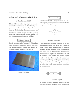
Substation Automation Products Distributed busbar protection REB500пЂ including line and transformer protection Product Guide Substation Automation Products Distributed busbar protection REB500 including line and transformer protection Main features • Low-impedance busbar protection • Stub and T-zone protection • High functional reliability due to two independent measurement criteria: - stabilized differential current algorithm - directional current comparison algorithm • Phase-by-phase measurement • Reduced CT performance requirements • High through-fault stability even in case of CT saturation • Full solid-state busbar replica • No switching of CT circuits • Only one hardware version for - 1 and 5 A rated currents - all auxiliary supply voltages between пЂ 48 V DC and 250 V DC - nominal frequencies of 50, 60 and пЂ 16.7 Hz • Short tripping times independent of the plant’s size or configuration • Centralized layout: Installation of hardware in one or several cubicles • Distributed layout: Bay units distributed and, in the case of location close to the feeders, with short connections to CTs, isolators, circuit breakers, etc. • Connections between bay units and central unit by fiber-optic cables - maximum permissible length 1200 m - for distributed and centralized layout • fiber-optic connections mean interferenceproof data transfer even close to HV power cables • Replacement of existing busbar protection schemes can be accomplished without restrictions (centralized layout) in the case of substation extensions e.g. by a mixture of centralized and distributed layout • Easily extensible Additional main features Page 2 REB500sys combines the well-proven numerical busbar and breaker failure protection REB500 of ABB with Main 2 or back-up protection for line or transformer feeders. The Main 2 / Group 1 or back-up protection is based on the well-proven protection function library of ABB line and transformer protection for 50, 60 and 16.7 Hz. • User-friendly, PC-based human machine interface (HMI) • Fully numerical signal processing • Comprehensive self-supervision • Binary logic and timer in the bay unit • Integrated event recording • Integrated disturbance recording for power system currents • A minimum of spare parts needed due to standardization and a low number of varying units • Communication facilities for substation monitoring and control systems via пЂ IEC 61850-8-1, IEC 60870-5-103 and LON • IEC 62439 standard redundant station bus communication • IEC 61850-9-2 LE process bus communication • Cyber security to support - User Access Management - User Activity Logging Options • Breaker failure protection (also separately operable without busbar protection) • End fault protection • Definite time overcurrent protection • Breaker pole discrepancy • Current and voltage release criteria • Disturbance recording for power system voltages • Separate I0 measurement for impedancegrounded networks • Communication with substation monitoring and control system (IEC 61850-8-1 /пЂ IEC 60870-5-103 / LON) • Internal user-friendly human machine interface with display • Redundant power supply for central units and/or bay units Main 2 / back-up bay protection • Definite and inverse time over- and undercurrent protection • Directional overcurrent definite and inverse time protection • Inverse time earth fault overcurrent protection • Definite time over- and undervoltage protection Substation Automation Products Distributed busbar protection REB500 including line and transformer protection • Three-phase current and three-phase voltage plausibility - checks for dead line, dead bus, dead line and bus Main 2 / back-up bay protection: пЂ Line protection • High-speed distance protection • Directional sensitive earth fault protection for grounded systems against high resistive faults in solidly grounded networks • Directional sensitive earth fault protection for ungrounded or compensated systems • Autoreclosure for - single-pole / three-pole reclosure - up to four reclosure sequences • Synchrocheck with - measurement of amplitudes, phase angles and frequency of two voltage vectors Group 1 / back-up bay protection: пЂ Transformer protection • High-speed transformer differential protection for 2- and 3-winding and auto-transformers • Thermal overload • Peak value over- and undercurrent protection • Peak value over- and undervoltage protection • Overfluxing protection • Rate of change frequency protection • Frequency protection • Independent T-Zone protection with transformer differential protection • Power protection Application REB500 REB500sys The numerical busbar protection REB500 is designed for the high-speed, selective protection of MV, HV and EHV busbar installations at a nominal frequency of 50, 60 and 16.7 Hz. The REB500sys is foreseen in MV, HV and EHV substations with nominal frequencies of 16.7, 50 Hz or 60 Hz to protect the busbars and their feeders. The bay protection functions included in REB500sys are used as Main 2 / Group 1 - or back-up protection. The structure of both hardware and software is modular enabling the protection to be easily configured to suit the layout of the primary system. The flexibility of the system enables all configurations of busbars from single busbars to quadruple busbars with transfer buses, ring busbars and 1ВЅ breaker schemes to be protected. In 1ВЅ breaker schemes the busbars and the entire diameters, including Stub/T-Zone can be protected. An integrated tripping scheme allows to save external logics as well as wiring. The capacity is sufficient for up to 60 feeders (bay units) and a total of 32 busbar zones. The numerical busbar protection REB500 detects all phase and earth faults in solidly grounded and resistive-grounded power systems and phase faults in ungrounded systems and systems with Petersen coils. The main CTs supplying the currents to the busbar protection have to fulfil only modest performance requirements (see page 18). The protection operates discriminatively for all faults inside the zone of protection and remains reliably stable for all faults outside the zone of protection. The system REB500sys is foreseen for all single or double busbar configurations (Line variants L-V1 to L-V7 and Transformer variant TV1 to T-V4). In 1ВЅ breaker configurations, variant L-V5 can be used for the bay level functions autoreclosure and synchrocheck. The capacity is sufficient for up to 60 feeders (bay units) and a total of 32 busbar zones. The REB500sys detects all bus faults in solidly and low resistive-grounded power systems, all kind of phase faults in ungrounded and compensated power systems as well as feeder faults in solidly, low resistive-grounded, compensated and ungrounded power systems. The protection operates selectively for all faults inside the zone of protection and remains reliably stable for all faults outside the zone of protection. REB500sys is perfectly suited for retrofit concepts and stepwise upgrades. The bay unit is used as a stand-alone unit for bay protection functions (e.g. line protection, autoreclosure and synchrocheck or 2- and 3 winding transformer protection or autonomous T-zone protection). The central unit can be added at a later stage for full busbar and breaker failure protection functionality. Page 3 Substation Automation Products Distributed busbar protection REB500 including line and transformer protection Application (contВґd) Depending on the network voltage level and the protection philosophy the following protection concepts are generally applied: - Line variant 5 (L-V5)пЂ as line variant L-V1 plus autoreclosure and synchrocheck. • Two main protection schemes per bay and one busbar protection.пЂ With REB500sys the protection concept can be simplified. Due to the higher integration of functionality one of the main protection equipment can be eliminated. • One main protection and one back-up protection scheme per bay, no busbar protection.пЂ With REB500sys a higher availability of the energy delivery can be reached, due to the implementation of busbar and breaker failure protection schemes where it hasn't been possible in the past because of economical reasons. - Line variant 6 (L-V6) for 16.7 HzпЂ non-directional overcurrent, distance protection, autoreclosure. Nine standard options are defined for Main 2/ Group 1 or back-up bay level functions: Line protection - Line variant 1 (L-V1)пЂ directional, non-directional overcurrent and directional earth fault protection - Line variant 2 (L-V2)пЂ as line variant L-V1 plus distance prot. - Line variant 3 (L-V3)пЂ as line variant L-V2 plus autoreclosure - Line variant 4 (L-V4)пЂ as line variant L-V3 plus synchrocheck Fig. 1 Page 4 - Line variant 7 (L-V7) for 16.7 HzпЂ as line variant L-V6 plus directional earth fault protection for grounded systems Transformer protection - Transformer variant 1 (T-V1)пЂ 2- or 3 winding transformer differential protection, thermal overload, current functions; applicable also as autonomous T-zone protection. - Transformer variant 2 (T-V2)пЂ 2-winding transformer differential protection, thermal overload, current functions, overfluxing protection, neutral overcurrent (EF). - Transformer variant 3 (T-V3)пЂ Distance protection for transformer back-up or 2-winding transformer differential protection, thermal overload, current functions, voltage functions, frequency functions, power function, overfluxing protection. - Transformer variant 4 (T-V4)пЂ Transformer oriented functions/ back-up functions -> thermal overload, current functions, voltage functions, frequency functions, power function, overfluxing protection. Substation Automation Products Distributed busbar protection REB500 including line and transformer protection PDIS RREC RSYN PDIF PDIF PTTR PTUC/PTOC PTUV/PTOV PVPH PVPH PVRC PTOF/PTUF PDUP/PDOP z z z z z z z z z z z z z z z z z z z z z z z z z z Transformer Variant 4 (T-V4) 50/60 Hz z z z z z z z z z z Transformer Variant 3 (T-V3) 50/60 Hz z z z z z z z z z z Transformer Variant 2 (T-V2) 50/60 Hz z z z z z z z z z z Transformer Variant 1 (T-V1) 50/60 Hz Line Variant 7 (L-V7) 16.7 Hz OCDT OCINV OVDT I0INV DIROCDT DIROCINV CHKI3PH CHKU3PH Line Variant 6 (L-V6) 16.7 Hz IEC61850 - Line Variant 5 (L-V5) 50/60Hz z z z z z z z z z z z z z z z z z z z z z z z z z z z z z z z z z z z z z z z z z z z - 51 51 59/27 51N 67 67 46 47 67N z z Line Variant 4 (L-V4) 50/60Hz z Com ER DR DR z Line Variant 3 (L-V3) 50/60Hz DIREFISOL PSDE DIST AR SYNC DIFTRA DIFTRA TH OCINST OVINST U/fDT U/fINV df/dt Freq P - BBP CZ OCDT PDIF PDIF RBRF PTOC PTOC PTOC PTOV/PTUV PDIF PTOC RDRE RDRE Option 32N 21 79 25 87T 87T 49 50 59 24 24 81 81 32 BBP I0 BFP EFP PDF Standard z z z z z z z z z z Protection function PTOC PTOC PTUV/PTOV PTOC PTOC PTOC PTOC PTUV DIREFGND PDEF 87B 87BN 50BF 51/62EF 51/62PD 51 59/27 87CZ 51 94RD 95DR 95DR Line Variant 2 (L-V2) 50/60Hz Busbar protection Busbar protection with neutral current Breaker failure protection inlcluding neutral current detection End-fault protection Breaker pole discrepancy Overcurrent check feature Voltage check feature Check zone Current plausibility check Overcurrent protection (def. time) Trip command re-direction Software matrix for inputs / outputs / trip matrix Event recording up to 1000 events Disturbance recorder (4 x I) Disturbance recorder (4 x I, 5 x U) up to 10 s at 2400 Hz Communication interface IEC 61850-8-1/ LON / IEC 60870-5-103 Time synchronization Redundant power supply for central- and/or bay units Isolator supervision Differential current supervision Comprehensive self-supervision Dynamic Busbar replica with display of currents WEB - Server Testgenerator for commissioning & maintenance Remote-HMI Delay / Integrator function Binary logic and Flip-Flop functions Definite time over- and undercurrent protection Inverse time overcurrent protection Definite time over- and undervoltage protection Inverse time earth fault overcurrent protection Directional overcurrent definite time protection Directional overcurrent inverse time protection Three phase current plausibility Three phase voltage plausibility Test sequenzer Direct. sensitive EF prot. for grounded systems Direct. sensitive EF prot. for ungrounded or compensated systems Distance protection Autoreclosure Synchrocheck Transformer differential protection 2 winding Transformer differential protection 3 winding Thermal overload Peak value over- and undercurrent protection Peak value over- and undervoltage protection Definite time overfluxing protection Inverse time overfluxing protection Rate-of-change frequency protection Frequency protection Power protection IEEE Main functionality Line Variant 1 (L-V1) 50/60Hz Table 1 Overview of the functionalities REB500 / REB500sys z z z z z z z z z z z z z z z z z z z z z z z z z z z z z z z z z z z z z z z z z z z z z z z z z z z z z z z Page 5 Substation Automation Products Distributed busbar protection REB500 including line and transformer protection Mode of пЂ installation There are three versions of installing the numerical busbar protection REB500 and the numerical station protection REB500sys: Distributed installation In this case, the bay units (see Fig. 24) are installed in casings or cubicles in the individual switchgear bays distributed around the Fig. 2 Distributed installation Centralized installation 19" mounting plates with up to three bay units each, and the central processing unit are mounted according to the size of the busbar system in one or more cubicles (see Fig. 23). A centralized installation is the ideal solution Fig. 3 Centralized installation Combined centralized and distributed installation Basically, the only difference between a distributed and a centralized scheme is the mounting location of the bay units and therefore it is possible to mix the two philosophies. Page 6 station and are connected to the central processing unit by optical fiber cables. The central processing unit is normally in a centrally located cubicle or in the central relay room. for upgrading existing stations, since veryпЂ little additional wiring is required and compared with older kinds of busbar protection, much more functionality can be packed into the same space. Substation Automation Products Distributed busbar protection REB500 including line and transformer protection System design Bay unit (500BU03) The bay unit (see Fig. 4) is the interface between the protection and the primary system process comprising the main CTs, isolators and circuit-breaker and performs the associated data acquisition, pre-processing, control functions and bay level protection functions. It also provides the electrical insulation between the primary system and the internal electronics of the protection. The input transformer module contains four input CTs for measuring phase and neutral currents with terminals for 1 A and 5 A. Additional interposing CTs are not required, because any differences between the CT ratios are compensated by appropriately configuring the software of the respective bay units. Optional input transformer module also contains five input voltage transformers for the measurement of the three-phase voltages and two busbar voltages and recording of voltage disturbances or 6 current transformers for transformer differential protection. (see пЂ Fig. 12). In the analog input and processing module, the analog current and voltage signals are converted to numerical signals at a sampling rate of 48 samples per period and then numerically preprocessed and filtered accordingly. Zero-sequence voltage and zero-current signals are also calculated internally. The Pro- cess data are transferred at regular intervals from the bay units to the central processing unit via the process bus. Every bay unit has 20 binary inputs and 16 relay outputs. The binary I/O module detects and processes the positions of isolators and couplers, blocking signals, starting signals, external resetting signals, etc. The binary input channels operate according to a patented pulse modulation principle in a nominal range of 48 to 250 V DC. The PC-based HMI program provides settings for the threshold voltage of the binary inputs. All the binary output channels are equipped with fast operating relays and can be used for either signaling or tripping purposes (see contact data in Table 8). A software logic enables the input and output channels to be assigned to the various functions. A time stamp is attached to all the data such as currents, voltages, binary inputs, events and diagnostic information acquired by a bay unit. Where more binary and analog inputs are needed, several bay units can be combined to form a feeder/bus coupler bay (e.g. a bus coupler bay with CTs on both sides of the bus-tie breaker requires two bay units). The bay unit is provided with local intelligence and performs local protection (e.g. breaker failure, end fault, breaker pole discrepancy), bay protection (Main 2 or back-up bay protections) as well as the event and disturbance recording. Central Unit (500CU03) Bay Unit (500BU03) DC DC Optical Interface DC DC Local HMI Process-bus SAS/SMS Interface Real-time Clock RS 232 Interface Local HMI CPU Uhr M odul I nt e r f ace I nt e rf ace M odul Central c es s - bu s tp u t CPU Module M odul Kopp ler DSP DP U nit Ko pp ler E/ A (500 CU03 ) DC D C Lo ca l Mod ul E/ A Re a l -ti m e Cl o c k S A S/ SM S In t e rfa c e RS 23 2 I n te rf a c e HM I CIM CP U M o d u le C IM CP U M odule Mem St a rc o u p le r Bi n a ry I/ O CP U M odule St ar c o u p le r Binary in/output registers A/D CPU Module CPU Module Filter Filter Starcoupler Binary I/O Star coupler Electrical insulation Fig. 4 Block diagram of a bay unit and a central unit Page 7 Substation Automation Products Distributed busbar protection REB500 including line and transformer protection System design (contВґd) In the event that the central unit is out of operation or the optical fiber communication is disrupted an alarm is generated, the bay unit will continue to operate, and all local and bay protection as well as the recorders (event and disturbance) will remain fully functional (stand-alone operation). The hardware structure is based on a closed, monolithic casing and presented in two mounting solutions: • Without local HMI: ideal solution if convenient access to all information via the central unit or by an existing substation automation system is sufficient. • With local HMI and 20 programmable LEDs (Fig. 5): ideal solution for distributed and kiosk mounting (AIS), since all information is available in the bay. For the latter option it is possible to have the HMI either built in or connected via a flexible cable to a fixed mounting position (seeпЂ Fig. 28). In the event of a failure, a bay unit can be easily replaced. The replacement of a bay unit can be handled in a simple way. During system start-up the new bay unit requests its address, this can be entered directly via its local HMI. The necessary setting values and configuration data are then downloaded automatically. Additional plug-and-play functionality Bay units can be added to an existing REB500 system in a simple way. Central unit (500CU03) The hardware structure is based on standard racks and only a few different module types for the central unit (see Fig. 4). The modules actually installed in a particular protection scheme depend on the size, complexity and functionality of the busbar system. A parallel bus on a front-plate motherboard establishes the interconnections between the modules in a rack. The modules are inserted from the rear. The central unit is the system manager, i.e. it configures the system, contains the busbar replica, assigns bays within the system, manages the sets of operating parameters, acts as process bus controller, assures synchronization of the system and controls communication with the station control system. The variables for the busbar protection function are derived dynamically from the process data provided by the bay units. The process data are transferred to the central processor via a star coupler module. Up to 10 bay units can be connected to the first central processor and 10 to the others. Central processors and star coupler modules are added for protection systems that include more than 10 bay units. In the case of more than 30 bay units, additional casings are required for accommodating the additional central processors and star coupler modules required. All modules of the central unit have a plugand-play functionality in order to minimize module configuration. One or two binary I/O modules can be connected to a central processing unit. The central unit comprises a local HMI with 20 programmable LEDs (Fig. 6), a TCP/IP port for very fast HMI500 connection within the local area network. Fig. 5 Bay unit Fig. 6 Page 8 Central unit Substation Automation Products Distributed busbar protection REB500 including line and transformer protection Functionality Busbar protection The protection algorithms are based on two well-proven measuring principles which have been applied successfully in earlier ABB lowimpedance busbar protection systems: where N is the number of feeders. The following two conditions have to be accomplished for the detection of an internal fault: k st пЂЅ • a stabilized differential current measurement • the determination of the phase relationship between the feeder currents (phase comparison) The algorithms process complex current vectors which are obtained by Fourier analysis and only contain the fundamental frequency component. Any DC component and harmonics are suppressed. The first measuring principle uses a stabilized differential current algorithm. The currents are evaluated individually for each of the phases and each section of busbar (protection zone). k=1 Differential current ( |пЃ“ пЃ‰ | ) in ip p Tr a e r a K setting = kst max Restraint area IK m in 0 0 Fig. 7 g Restraint current (пЃ“|пЃ‰|) Tripping characteristic of the stabilized пЂ differential current algorithm. N  ILn nпЂЅ1 IDiff пЂѕ IK min whereпЂ kst kst max IK min (3) (4) stabilizing factor stabilization factor limit. пЂ A typical value is kst max = 0.80 differential current pick-up value The above calculations and evaluations are performed by the central unit. пЂ The second measuring principle determines the direction of energy flow and involves comparing the phases of the currents of all the feeders connected to a busbar section. The fundamental frequency current phasors пЃЄ1..n (5) are compared. In the case of an internal fault, all of the feeder currents have almost the same phase angle, while in normal operation or during an external fault at least one current is approximately 180В° out of phase with the others. пѓ© ImпЂЁI пЂ© пѓ№ пЃЄn пЂЅ arctanпѓЄ Ln пѓє пѓ«ReпЂЁILn пЂ©пѓ» (5) The algorithm detects an internal fault when the difference between the phase angles of all the feeder currents lies within the tripping angle of the phase comparator (see Fig. 8). In Fig. 7, the differential current is IDiff пЂЅ IDiff пЂѕ k st max IRest (1) and the restraint current IRest пЂЅ N  ILn nпЂЅ1 (2) Page 9 Substation Automation Products Distributed busbar protection REB500 including line and transformer protection Functionality (contВґd) Case 1: External fault пЃ„пЃЄпЂ = 144В° Im Busbar пЃЄпЂ±пЂІпЂ = 144В° I2 Re I1 Operating characteristic Case 2: Internal fault пЃ„пЃЄ = 36В° 180В° Im Phase-shift Restraint area пЃ„пЃЄ 74В° пЃ„пЃЄ max = 74В° Tripping area 0В° Case Fig. 8 1 2 I1 This first timer operates in a stand-alone mode in the bay unit. If the fault still persists at the end of the second time delay, the breaker failure function uses the busbar replica to trip all the other feeders supplying the same section of busbar via their bay units. Re I2 пЃЄпЂ±пЂІпЂ = 36В° Characteristic of the phase comparator for determining energy direction A remote tripping signal can be configured in the software to be transmitted after the first or second timer. Phase-segregated measurements in each bay unit cope with evolving faults. The task of processing the algorithms is shared between the bay units and the central processing unit. Each of the bay units continuously monitors the currents of its own fee-der, preprocesses them accordingly and then filters the resulting data according to a Fourier function. The analog data filtered in this way are then transferred at regular intervals to the central processing unit running the busbar protection algorithms. End fault protection In order to protect the “dead zone” between an open circuit-breaker and the associated CTs, a signal derived from the breaker position and the close command is applied. Depending on the phase-angle of the fault, the tripping time varies at Idiff/IkminпЂ п‚і5 between 20 and 30 ms including the auxiliary tripping relay. This function is performed in a stand-alone mode in the bay unit. Optionally, the tripping signal can be interlocked by a current or voltage release criteria in the bay unit that enables tripping only when a current above a certain minimum is flowing, respectively the voltage is below a certain value. Breaker failure protection The breaker failure functions in the bay units monitor both phase currents and neutral current independently of the busbar protection. They have two timers with individual settings. Operation of the breaker failure function is enabled either: • internally by the busbar protection algorithm (and, if configured, also by the internal line protection, overcurrent or pole discrepancy protection features) of the bay level • externally via a binary input, e.g. by the line protection, transformer protection etc. After the delay of the first timer has expired, a tripping command can be applied to a second Page 10 tripping coil on the circuit-breaker and a remote tripping signal transmitted to the station at the opposite end of the line. The end fault protection is enabled a certain time after the circuit-breaker has been opened. In the event of a short circuit in the dead zone the nearest circuit-breakers are tripped. Overcurrent function A definite time overcurrent back-up protection scheme can be integrated in each bay unit. (The operation of the function, if para-meterized, may start the local breaker failure protection scheme). This function is performed in a stand-alone mode in the bay unit. Current release criteria The current release criteria is only performed in the bay unit. It is effective for a busbar protection trip and for an intertripping signal (including end fault and breaker failure) and prevents those feeders from being tripped that are conducting currents lower than the setting of the current release criteria. Voltage release criteria The voltage criterion is measured in the bay unit. The function can be configured as release criterion per zone through internal linking in the central unit. This necessitates the existence of one set of voltage transformers per zone in one of the bay units. Tripping Substation Automation Products Distributed busbar protection REB500 including line and transformer protection is only possible if the voltage falls short of (U<) or exceeds (U0>) the set value. Additionally this release criterion can be configured for each feeder (voltage transformers must be installed). For details see Table 22. Check zone criterion The check zone algorithm can be used as a release criterion for the zone-discriminating low-impedance busbar protection system. It is based on a stabilized differential current measurement, which only acquires the feeder currents of the complete busbar. The isolator / breaker positions are not relevant for this criterion. Neutral current detection I0 Earth fault currents in impedance-grounded systems may be too low for the stabilized differential current and phase comparison functions to detect. A function for detecting the neutral current is therefore also available, but only for single phase-to-earth faults. Pole discrepancy A pole discrepancy protection algorithm supervises that all three poles of a circuitbreakers open within a given time. A disturbance record can be triggered by either the leading or lagging edges of all binary signals or by events generated by the internal protection algorithms. Up to 10 general-purpose binary inputs may be configured to enable external signals to trigger a disturbance record. In addition, there is a binary input in the central and the bay unit for starting the disturbance recorders of all bay units. The number of analog channels that can be recorded, the sampling rate and the recording period are given in Table 14. A lower sampling rate enables a longer period to be recorded. The total recording period can be divided into a maximum of 15 recording intervals per bay unit. Each bay unit can record a maximum of 32 binary signals, 12 of which can be configured as trigger signals. The function can be configured to record the pre-disturbance and post-disturbance states of the signals. The user can also determine whether the recorded data is retained or overwritten by the next disturbance (FIFO = First In, First Out). This function monitors the discrepancy between the three-phase currents of the circuitbreaker. This function is performed in a stand-alone mode in the bay unit (see page 7). When it picks up, the function does not send an intertripping signal to the central unit, but, if configured, it starts the local breaker failure protection (BFP logic 3). Note: Stored disturbance data can be transferred via the central unit to other computer systems for evaluation by programs such as PSM505 [3]. Files are transferred in the COMTRADE format. This function is also performed in a standalone mode in the bay unit. Event recording The events are recorded in each bay unit. A time stamp with a resolution of 1ms is attached to every binary event. Events are divided into the three following groups: After retrieving the disturbance recorder data, it is possible to display them graphically with PSM505 directly. • test events Communication interface Where the busbar protection has to communicate with a station automation system (SAS), a communication module is added to the central unit. The module supports the interbay bus protocols IEC 61850-8-1, IEC 60870-5103 and LON. The events are stored locally in the bay unit or in the central unit. The IEC 61850-8-1 interbay bus transfers via either optical or electrical connection: Disturbance recording This function registers the currents and the binary inputs and outputs in each bay. Voltages can also be optionally registered (see Table 14). • differential current of each protection zone • system events • protection events • monitoring information from REB500 central unit and bay units • binary events (signals, trips and diagnostic) • trip reset command Page 11 Substation Automation Products Distributed busbar protection REB500 including line and transformer protection Functionality (contВґd) • disturbance recording data (via MMS file transfer protocol) • time synchronization with Simple Network Time Protocol (SNTP) • two independent time servers are supported. Server 2 as backup time The LON interbay bus transfers via optical connection: (protection zones). The system monitors any inconsistencies of the binary input circuits connected to the isolator auxiliary contacts and generates an alarm after a set time delay. In the event of an isolator alarm, it is possible to select the behavior of the busbar protection: • blocked • differential currents of each protection zone • zone-selective blocked • binary events (signals, trips and diagnostic) • remain in operation • trip reset command • disturbance recording data (via HMI500) Table 2 • time synchronization N/O contact: “Isolator CLOSED” N/C contact:пЂ вЂњIsolator OPEN” open open open closed OPEN closed open CLOSED closed closed CLOSEDпЂ + delayed isolator alarm, + switching prohibited signal The IEC 60870-5-103 interbay bus transfers via either optical or electrical connection: • time synchronization • selected events listed in the public part • all binary events assigned to a private part • all binary events in the generic part • trip reset command Test generator The HMI program (HMI500) which runs on a PC connected to either a bay unit or the central processing unit includes a test generator. During commissioning and system maintenance, the test generator function enables the user to: • activate binary input and output signals • monitor system response. • blocked • test the reclosure cycles • remain in operation The test sequencer enables easy testing of the bay protection without the need to decommission the busbar protection. Up to seven se-quences per test stage can be started. The sequences can be saved and reactivated for future tests. Isolator supervision The isolator replica is a software feature without any mechanical switching elements. The software replica logic determines dynamically the boundaries of the protected busbar zones Page 12 Last position stored (for busbar protection)пЂ + delayed isolator alarm, + switching prohibited signal Differential current supervision The differential current is permanently supervised. Any differential current triggers a timedelayed alarm. In the event of a differential current alarm, it is possible to select the behavior of the busbar protection: • test the trip circuit up to and including the circuit-breaker • establish and perform test sequences with virtual currents and voltages for the bay protection of the REB500sys Isolator position • zone-selective blocked Trip redirection A binary input channel can be provided to which the external signal monitoring the circuit-breaker air pressure is connected. Tripping is not possible without active signal. When it is inactive, a trip generated by the respective bay unit is automatically redirected to the station at the opposite end of the line and also to the intertripping logic to trip all the circuit-breakers connected to the same section of busbar. The trip redirection can also be configured with a current criterion (current release criteria). Substation Automation Products Distributed busbar protection REB500 including line and transformer protection Human machine interface (HMI) The busbar protection is configured and maintained with the aid of human machine interfaces at three levels. Local HMI The local display interface installed in the central unit and in the bay units comprises: • a four-line LCD with 16 characters each for displaying system data and error messages • keys for entering and display as well as 3 LEDs for the display of trips, alarms and normal operation. • in addition 20 freely programmable LEDs for user-specific displays on the bay unit 500BU03 and central unit 500CU03. The following information can be displayed: • measured input currents and voltages • measured differential currents (for the busbar protection) • system status, alarms • switchgear and isolator positions (within the busbar protection function) • starting and tripping signals of protection functions Additional functionalities Bay level functions These functions are based on the well established and well-proven functions built in the ABB line and transformer protection. The bay level functions contain all the relevant additional functions, which are normally requested of a line and transformer protection scheme. External HMI (HMI500) More comprehensive and convenient control is provided by the external HMI software running on a PC connected to an optical interface on the front of either the central unit or a bay unit. The optical interface is completely immune to electrical interference. The PC software facilitates configuration of the entire busbar protection, the set-ting of parameters and full functional checking and testing. The HMI500 can also be operated via the LON Bus on MicroSCADA for example, thus eliminating a separate serial connection to the central unit. The HMI runs under MS WINDOWS NT, WINDOWS 98, WINDOWS 2000 and WINDOWS XP. The HMI500 is equipped with a comfortable on-line help function. A data base comparison function enables a detailed comparison between two configuration files (e.g. between the PC and the central unit or between two files on the PC). Remote HMI A second serial interface at the rear of the central unit provides facility for connecting a PC remotely via either an optical fiber, TCP/IP or modem link. The operation and function of HMI500 is the same whether the PC is connected locally or remotely. The line protection functions (L-V1 - L-V7) are used as Main 2 or back-up for lines as well as for transformer bays. The transformer protection functions (T-V1 - T-V4) are used as Group 2 or back-up bay protection for transformer bays or as an independent T-Zone protection. Page 13 Substation Automation Products Distributed busbar protection REB500 including line and transformer protection Additional functionalities (contВґd) High-speed distance protection • Overcurrent or underimpedance starters with polygonal characteristic • Five distance zones (polygon for forwards and reverse measurement) • Load-compensated measurement • Definite time overcurrent back-up protection (short-zone protection) Transformer differential protection • For two- and three-winding transformers • System logic • Auto transformers - switch-onto-fault • Three-phase function - overreach zone • Current-adaptive characteristic • Voltage transformer circuit supervision • Power swing blocking function • HF teleprotection. The carrier-aided schemes include: • High stability for external faults and current transformer saturation • No auxiliary transformers necessary because of vector group and CT ratio compensation - permissive underreaching transfer tripping • Inrush restraint using 2nd harmonic - permissive overreaching transfer tripping The transformer differential protection function can also be used as an autonomous T-zone protection in a 1ВЅ breaker scheme. - blocking scheme with echo and transient blocking functions • Load-compensated measurement - fixed reactance slope - reactance slope dependent on load value and direction (ZHV<) • Parallel line compensation • Phase-selective tripping for single and three-pole autoreclosure • Four independent, user-selectable setting groups. In the supervision mode the active and reactive power with the respective energy direction is displayed by the HMI500. Autoreclosure The autoreclosure function permits up to four three-phase autoreclosure cycles. The first cycle can be single phase or three-phase. If the REB500sys autoreclosure function is employed, it can be used as a back-up for the autoreclosure realized externally (separate equipment or in the Main 1 protection). When the autoreclosure function is realized outside of REB500sys, all input and output signals required by the external autoreclosure equipment are available in order to guarantee correct functionality. Page 14 Synchrocheck The synchrocheck function determines the difference between the amplitudes, phase angles and frequencies of two voltage vectors. The synchrocheck function also contains checks for dead line and dead bus. Thermal overload This function protects the insulation against thermal stress. This protection function is normally equipped with two independently set levels and is used when oil overtemperature detectors are not installed. Peak value over- and undercurrent protection These functions are used for current monitoring with instantaneous response and where insensitivity to frequency is required. Peak value over- and undervoltage protection This function is used for voltage monitoring with instantaneous response and where insensitivity to frequency is required. Frequency function The function is used either as an over-/ underfrequency protection, or for load-shedding in the event of an overload. Several stages of the frequency protection are often needed. This can be achieved by configuring the frequency function several times. Rate of change frequency protection df/dt This function is used for the static, dynamic and adaptive load-shedding in power utilities and industrial distribution systems. The function supervises the rate-of-change df/dt of one voltage input channel. Several stages of the rate-of-change frequency protection are often Substation Automation Products Distributed busbar protection REB500 including line and transformer protection needed. This can be achieved by configuring the rate-of-change frequency function several times. Definite time overfluxing protection This function is primarily intended to protect the iron cores of transformers against excessive flux. The function works with a definite time delay. The magnetic flux is not measured directly. Instead the voltage/frequency-ratio, which is proportional to the flux is monitored. Inverse time overfluxing protection This function is primarily intended to protect the iron cores of transformer against excessive flux. The function works with an inverse time delay. The inverse curve ca be set by a table of 10 values and the times t-min and tmax. The magnetic flux is not measured directly. Instead the voltage/frequency-ratio, which is proportional to the flux is monitored. Power function This function provides single, or three phase measurement of the real or apparent power. The function can be configured for monitoring reverse, active or reactive power (power direction setting). Phase angle errors of the CT/VT inputs can be compensated by setting. The operating mode can be configured either to underpower or to overpower protection. Logics and delay/integrator These functions allow the user the engineering of some easily programmable logical functions and are available as standard also in the REB500 functionality. Directional sensitive earth fault protection for grounded systems A sensitive directional ground fault function based on the measurement of neutral current and voltage is provided for the detection of high-resistance ground faults in solidly or lowresistance grounded systems. The scheme operates either in a permissive or blocking mode and can be used in conjunction with an inverse time earth fault overcurrent function. In both cases the neutral current and voltage can be derived either externally or internally. This function works either with the same communication channel as the distance protection scheme or with an independent channel. Directional sensitive earth fault protection for ungrounded or compensated systems The sensitive earth fault protection function for ungrounded systems and compensated systems with Petersen coils can be set for either forwards or reverse measurement. The characteristic angle is set to В±90В° пЂ (U0 В· I0 В· sin пЃЄ) in ungrounded systems and to 0В° or 180В° (U0 В· I0 В· cos пЃЄ) for systems with Petersen coils. The neutral current is always used for measurement in the case of systems with Petersen coils, but in ungrounded systems its use is determined by the value of the capacitive current and measurement is performed by a measuring CT to achieve the required sensitivity. To perform this function the BU03 with 3I, 1MT and 5U is required. Definite time over- and undercurrent protection This function is used as Main 2 or as back-up function respectively for line, transformer or bus-tie bays. This function can be activated in the phase- and/or the neutral current circuit. Inverse time overcurrent protection The operating time of the inverse time overcurrent function reduces as the fault current increases and it can therefore achieve shorter operating times for fault locations closer to the source. Four different characteristics according to British Standard 142 designated normal inverse, very inverse, extremely inverse and long time inverse but with an extended setting range are provided. The function can be configured for single phase measurement or a combined three-phase measurement with detection of the highest phase current. Inverse time earth fault overcurrent protection The inverse time earth fault overcurrent function monitors the neutral current of the system. Four different characteristics according to British Standard 142 designated normal inverse, very inverse, extremely inverse and long time inverse but with an extended setting range are provided. Directional overcurrent definite / inverse time protection The directional overcurrent definite time function is available either with inverse time or definite time overcurrent characteristic. This function comprises a voltage memory for faults close to the relay location. The function response after the memory time has elapsed can be selected (trip or block). Definite time over- and undervoltage protection This function works with a definite time delay with either single or three-phase measurement. Page 15 Substation Automation Products Distributed busbar protection REB500 including line and transformer protection Additional functionalities (cont’d) Three-phase current plausibility This function is used for checking the sum and the phase sequence of the three-phase currents. Three-phase voltage plausibility This function is used for checking the sum and the phase sequence of the three-phase voltages. AdditionalпЂ features Self-supervision All the system functions are continuously monitored to ensure the maximum reliability and availability of the protection. In the event of a failure, incorrect response or inconsistency, the corresponding action is taken to establish a safe status, an alarm is given and an event is registered for subsequent diagnostic analysis. Resetting the trip commands/-signals The following resetting modes can be selected for each binary output (tripping or signal outputs): Important items of hardware (e.g. auxiliary supplies, A/D converters and main and program memories) are subjected to various tests when the system is switched on and also during operation. A watchdog continuously monitors the integrity of the software functions and the exchange of data via the process bus is also continuously supervised. The processing of tripping commands is one of the most important functions from the reliability and dependability point of view. Accordingly, every output channel comprises two redundant commands, which have to be enabled at regular intervals by a watchdog. If the watchdog condition is not satisfied, the channels are blocked. Extension of the system The system functions are determined by software, configured using the software configuration tool. The system can be completely engineered in advance to correspond to the final state of the station. The software modules for new bays or features can be activated using the HMI500 when the primary plant is installed or the features are needed. Additional system functions, e.g. breaker failure, end fault protection or bay level пЂ back-up / Main 2 functions can be easily activated at any time without extra hardware. Page 16 • Latches until manually reset • Resets automatically after a delay Inspection/maintenance A binary input is provided that excludes a bay unit from evaluation by the protection system. It is used while performing maintenance respectively inspection activities on the primary equipment. Redundant power supplies (Option) Two power supply modules can be fitted in a redundant arrangement, e.g. to facilitate maintenance of station batteries. This is an option for the central unit as well as for the bay unit. Time synchronization The absolute time accuracy with respect to an external time reference depends on the method of synchronization used: • no external time synchronization:пЂ accuracy approx. 1 min. per month • periodic time telegram with minute pulse (radio or satellite clock or station control system): accuracy typically В±10 ms • periodic time telegram as above with second pulse: accuracy typically В±1 ms • a direct connection of a GPS or DCF77 to the central unit is possible: accuracy typically В±1 ms • Furthermore, the time synchronization can be done, if available, via the interbay bus IEC103, LON or SNTP (in case IEC618508-1 is used) The system time may also be synchronized by a minute pulse applied to a binary input on the central unit. Substation Automation Products Distributed busbar protection REB500 including line and transformer protection Requirements Optical fiber cables A distributed busbar protection layout requires optical fiber cables and connectors with the following characteristics: • 2 optical fiber cores per bay unit • glass fibers with gradient index Please observe the permissible bending radius when laying the cables. The following attenuation figures are typical values which may be used to determine an approximate attenuation balance for each bay: • diameter of core and sheath 62.5, пЂ respectively 125 пЃm Optical equipment TypicalпЂ attenuation • maximum permissible attenuation п‚Ј5 dB for gradient index (840 nm) 3.5 dB/km • FST connector (for 62.5 пЃm optical fibers) per connector 0.7 dB • rodent protected and longitudinally waterproof if in cable ducts per cable joint 0.2 dB Central unit 1200 m 1m FST-connector Bay unit 1m FST-connector п‚ЈпЂµпЂ dB Fig. 9 Attenuation Isolator auxiliary contact Auxiliary contacts on the isolators are connected to binary inputs on the bay units and control the status of the busbar replica in the numerical busbar protection. must close before the isolator main contact gap reaches its flashover point. One potentially-free N/O and N/C contact are required on each isolator. The N/O contact signals that the isolator is “CLOSED” and the N/C contact that the isolator is “OPEN”. During the closing movement, the N/O contact Conversely, during the opening movement, the N/O contact must not open before the isolator main contact gap exceeds its flashover point. If this is not the case, i.e. the contact signals вЂ�no longer closed’ beforehand, then the N/C contact may not signal “OPEN” before the flashover point has been exceeded. Close end position Open end position Close isolator Open isolator Isolator Auxiliary contacts: Flashover gap „CLOSED“ normally open „OPEN“ normally closed must be closed may be closed must be open Fig. 10 Switching sequence of the auxiliary contacts that control the busbar replica Page 17 Substation Automation Products Distributed busbar protection REB500 including line and transformer protection Requirements (contВґd) Circuit-breaker replica When the circuit-breaker replica is read in the feeder or the bus-tie breaker, the circuitbreaker CLOSE command must also be connected. Main current transformer The algorithms and stabilization features used make the busbar protection largely insensitive to CT saturation phenomena. Main CTs types TPS (B.S. class x), TPX, TPY, 5P.. or 10P.. are permissible. TPX, TPY and TPZ CTs may be mixed within one substation in phase-fault schemes. The relatively low CT performance needed for the busbar protection makes it possible for it to share protection cores with other protection devices. I1N = rated primary CT current Taking the DC time constant of the feeder into account, the effective n' becomes: (2) n' п‚і10пЂ for TN п‚Ј120 ms, or n' п‚і20пЂ for 120 ms <TN п‚Ј300 ms. where: TN = DC time constant Example: IKmax = 30000 A I1N = 1000 A TN п‚Ј 120 ms Current transformer requirements for stability during external faults (Busbar protection) The minimum CT requirements for 3-phase systems are determined by the maximum fault current. Applying relationships (1) and (2): The effective accuracy limit factor (n') must be checked to ensure the stability of the busbar protection during external faults. Selected: The rated accuracy limit factor is given by the CT manufacturer. Taking account of the burden and the CT losses, the effective accuracy limit factor n' becomes: n' пЂЅ n пѓ— where: n = PN = PE = PB = PN пЂ« PE PB пЂ« PE rated accuracy limit factor rated CT power CT losses burden at rated current In the case of schemes with phase-by-phase measurement, n' must satisfy the following two relationships: (1) Page 18 where: IKmax = max. primary through-fault current 1 пѓ— I Kmax nп‚ў п‚і -----------------5 пѓ— I 1N (1) (2) 30000 n п‚ў ---------------- = 6 5000 n' п‚іпЂ 10 n' п‚іпЂ 10 The current transformer requirements for REB500sys for Line and Transformer protection are described in a separate publication [1]. Pick-up for internal faults In the case of internal busbar faults, CT saturation is less likely, because each CT only conducts the current of its own feeder. Should nevertheless CT saturation be possible, it is important to check that the minimum fault current exceeds the setting for Ikmin. Note: For systems that measure I0, the REB500 questionnaire 1MRB520371-Ken should be filled in and submitted to ABB, so that the CT requirements can be checked in order to ensure proper I0 measurement. Substation Automation Products Distributed busbar protection REB500 including line and transformer protection Technical data Table 3 General data Temperature range: - operation - storage and transport Climate tests - Cold - Dry heat - Change of temperature - Damp heat пЂ (long-time) -10В°C...+ 55В°C - 40В°C...+ 85В°C -25В°C / 16 h +70В°C / 16 h -25В° to 70В°C, 1В°/min, 2 cycles IEC 60255-1 (2009), EN60255-1 (2010) IEC 60255-27 (2005), EN 60255-27 (2006) IEC 60255-1 (2009), EN60255-1 (2010) IEC 60255-27 (2005), EN 60255-27 (2006) EN 60068-2-1 (2008), IEC 60068-2-1 (2007), EN 60068-2-2 (1993), IEC 60068-2-2 (2007), EN 60068-2-14 (2010), IEC 60068-2-14 (2009) EN 60068-2-78 (2002), IEC 60068-2-78 (2001) +40В°C; 93% rel. hum. / 10 days Thermal withstand of insulating materials EN 60950 (1995) Sec. 5.1 Clearance and creepage distances EN 60255-5 (2001), IEC 60255-5 (2000),пЂ EN 60950 (1995), IEC 60950 (1995) Insulation resistance tests 0.5 kV / >100 MOhm EN 60255-5 (2001), IEC 60255-5 (2000), VDE 0411 Dielectric tests 2 kV AC or 3 kV DC / 1 min 1 kV AC or 1.4 kV DC / 1 min (across open contacts) EN 60255-5 (2001), IEC 60255-5 Cl.C (2000) 1.2/50 пЃs/0.5 JouleпЂ 5 kV AC EN 60255-5 (2001), IEC 60255-5 (2000) Impulse test EN 60950 (1995), IEC 60950 (1995) BS 142-1966, ANSI/IEEE C37.90-1989 Table 4 Electromagnetic compatibility (EMC) Immunity 1 MHz burst disturbance tests 1.0/2.5 kV, 1 MHz 400 Hz rep. freq. IEC 60255-22-1, Cl. 3 (2007), ANSI/IEEE C37.90.1-1989 Immunity Industrial environment EN 50263 (2000) Electrostatic discharge test (ESD) - air discharge - contact discharge Class 3 EN 61000-4-2 (2009),пЂ IEC 61000-4-2 (2008) EN 60255-22-2 (2009), пЂ IEC 60255-22-2 (2008) Fast transient test (burst) Class 4 2/4 kV EN 61000-4-4 (2005), пЂ IEC 61000-4-4 (2004) EN 60255-22-4 (2009), пЂ IEC 60255-22-4 (2008) Power frequency magneticпЂ field immunity test (50/60 Hz) - continuous field - short duration Class 4 EN 61000-4-8 (2009), пЂ IEC 61000-4-8 (2009) 8 kV 6 kV 30 A/m 300 A/m Radio frequency interference пЂ Class 3 test (RFI) 0.15 - 80 MHz, 80% amplitude modulated 10 V 80 - 1000 MHz, 80% amplitude modulated 10 V/m 900 MHz, pulse modulated 10 V/m EN 61000-4-6 (2009), IEC 61000-4-6 (2008) Emission - Conducted RFI - Radiated RFI Industrial environment Test procedure EN 55022 (1998), CISPR 22 (1990) Surge Class 3 1kV / 2kV EN 60255-21-3 (1995), IEC 60255-21-3 (1993), IEEE 344; 2004 EN 61000-4-3 (2011), IEC 61000-4-3 (2002) Page 19 Substation Automation Products Distributed busbar protection REB500 including line and transformer protection Technical data (contВґd) Table 5 Mechanical tests Vibration and shock Vibration - reponse test - endurance test Shock and bump - shock - bump Seismic (SSE) 10 to 150 Hz / 0.5 gn 10 to 150 Hz / 1 gn EN 60255-21-1 (1996), пЂ IEC 60255-21-1 (1988) EN 60068-2-6 (2008) IEC 60068-2-6 (2007) IEEE 344; 2004 Class 1 A = 15 gn; D = 11 ms pulse/ axis = 3 A = 10 gn; D = 16 ms pulse/ axis = 1000 EN 60255-21-2 (1996), пЂ IEC 60255-21-2 (1988) EN 60068-2-27 (2010), пЂ IEC 60068-2-27 (2008) IEEE 344; 2004 1 to 35 Hz, 1/2 gn EN 60255-21-3 (1995), пЂ IEC 60255-21-3 (1993), IEEE 344; 2004 Table 6 Enclosure protection classes Bay unit 19" central unit Cubicle (see Table 12) IP40 IP20 IP40-50 Hardware modules Table 7 Analog inputs (Bay unit) Currents 4/ 6/ 8/ 9 input channels I1, I2, I3, I4/ I1, I2, I3, I4, I5, I6/ I1, I2, I3, I4, I5, I6, I7, I8/ I1, I2, I3, I4, I5, I6, I7, I8, I9 Rated current (IN) 1 A or 5 A by choice of terminals, пЂ adjustable CT ratio via HMI500 Thermal ratings: continuous 4 x IN for 10 s for 1 s 30 x IN 100 x IN 1 half-cycle 250 x IN (50/60 Hz) (peak) Burden per phase EN 60255-6 (1994), IEC 60255-6 (1988), пЂ VDE 0435, part 303 EN 60255-6 (1994), IEC 60255-6 (1988),пЂ VDE 0435, Part 303 п‚Ј0.02 VA at IN = 1 A пЂ п‚Ј0.10 VA at IN = 5 A Voltages (optional) 1/ 3/ 5 input channels U1/ U1, U2, U3/ U1, U2, U3, U4, U5 Rated voltage (UN) 100 V, 50/60 Hz, 16.7 Hz 200 V, 50/60 Hz 500BU03 VT ratio adjustable via HMI500 Thermal ratings: continuous 2 x UN for 10 s 3 x UN Burden per phase п‚Ј0.3 VA at UN Common data Rated frequency (fN) 50 Hz, 60 Hz, 16.7 Hz пЂ adjustable via HMI500 Page 20 EN 60255-6 (1994), IEC 60255-6 (1988), VDE 0435, part 303 Substation Automation Products Distributed busbar protection REB500 including line and transformer protection Table 8 Binary inputs/outputs (Bay unit, Central unit) Binary outputs General Operating time 3 ms (typical) Max. operating voltage п‚Ј250 V AC/DC Max. continuous rating п‚Ј8 A Max. make and carry for 0.5 s п‚Ј30 A Max. making power at 110 V DC п‚Ј3300 W Binary output reset response, programmable per output - latched - automatic reset (delay 0...60 s) Heavy-duty N/O contacts CR08...CR16, 500BU03 Heavy-duty N/O contacts CR01...CR04, CR07...CR09 - 500CU03 Breaking current for (L/R = 40 ms) 1 contact 2 contacts in series U < 50 V DC п‚ЈпЂ 1.5 AпЂ U < 120 V DC п‚ЈпЂ 0.3 AпЂ U < 250 V DC п‚ЈпЂ 0.1 A U < 50 V DC п‚ЈпЂ 5 A U < 120 V DC п‚ЈпЂ 1 A U < 250 V DC п‚ЈпЂ 0.3 A Signalling contacts CR01...CR07, 500BU03 Signalling contacts CR05, CR06 - 500CU03 Breaking current U < 50 V DC п‚ЈпЂ 0.5 AпЂ U < 120V DC п‚ЈпЂ 0.1 AпЂ U < 250V DC п‚ЈпЂ 0.04 A Binary inputs Number of inputs per bay unit 20 optocouplers пЂ 9 groups with common terminal Number of inputs for central unit 12 optocouplers per binary I/O module (max. 2)пЂ 3 groups with common terminal Voltage range (Uoc) 48 to 250 V DC Pick-up setting via HMI500 Pick-up current п‚і10 mA Operating time <1 ms Table 9 Auxiliary supply Module type Bay unit Central unit Input voltage range (Uaux) В±25% 48 to 250 V DC 48 to 250 V DC Fuse no fuse 10 A slow Load 11 W 100 W Common data Max. input voltage interruption during which output voltage maintained >50 ms; IEC 60255-11 (1979), VDE 0435, Part 303 Frontplate signal green "standby" LED Switch ON/OFF Redundancy of power supply optional in bay and in central unit Page 21 Substation Automation Products Distributed busbar protection REB500 including line and transformer protection Technical data (contВґd) Table 10 Optical interfaces Number of cores 2 fiber cores per bay unit Core/sheath diameter 62.5/125 пЃm (multi-mode) Max. permissible attenuation п‚Ј5 dB (see Fig. 9) Max. length approx. 1200 m Connector Type FST for 62.5 пЃm optical fiber cables Table 11 Mechanical design Mounting Bay unit flush mounting on frames or in cubicles HMI integrated or separately mounted Central unit flush mounting on frames or in cubicles Table 12 Cubicle design Cubicle Standard type RESP97 (for details see 1MRB520159-Ken) Dimensions w x d x h 800 x 800 x 2200 mm (single cubicle)пЂ 1600 x 800 x 2200 mm (double cubicle)пЂ 2400 x 800 x 2200 mm (triple cubicle) *) *) largest shipping unit Total weight (with all units inserted) approx. 400-600 kg per cubicle Terminals Terminal type CTs Phoenix URTK/S 0.5 - 10 mm2 0.5 - 6 mm2 VTs Phoenix URTK/S 0.5 - 10 mm2 0.5 - 6 mm2 2 0.2 - 6 mm2 Connection data Solid Strand Power supply Phoenix UK 6 N 0.2 - 10 mm Tripping Phoenix UK 10-TWIN 0.5 - 16 mm2 Binary I/Os Phoenix UKD 4-MTK-P/P 0.2 - 4 mm2 Internal wiring gauges CTs 2.5 mm2 stranded VTs 1.5 mm2 stranded Power supply 1.5 mm2 stranded Binary I/Os 1.5 mm2 stranded Recording facilities Table 13 Event recorder Page 22 Event recorder Bay unit Central unit System events Protection events Test events 100 total 1000 total 0.5 - 10 mm2 0.2 - 2.5 mm2 Substation Automation Products Distributed busbar protection REB500 including line and transformer protection Table 14 Disturbance recorder Analog channel Recording periodпЂ Sample rate selectable 4 currents or 9 currents 4 currents and 5 voltages 802 Hz (16.7 Hz) 2400 Hz (50 Hz) 2880 Hz (60 Hz) Standard X X*) 1.5 s 3s 6s Option 1 X X 6s 12 s 24 s Option 2 X X 10 s 20 s 40 s Options 401 Hz (16.7 Hz) 1200 Hz (50 Hz) 1440 Hz (60 Hz) 600 Hz (50 Hz) 720 Hz (60 Hz) Number of disturbance records = total recording time / set recording period (max.15) Independent settings for pre-fault and post-fault period (min. setting 200 ms). Format: COMTRADE 91 and COMTRADE 99 *) in Standard, voltage channels are recorded, if existing Table 15 Interbay bus protocols IEC 61850-8-1 IEC 61850-8-1 interbay bus supports - Time synchronization via SNTP: typical accuracy В± 1 msпЂ - Two independent time servers are supported. Server 2 as backup timeпЂ - Optical or electrical connectionпЂ - Differential current of each protection zoneпЂ - Monitoring information from REB500 central unit and bay unitпЂ - Binary events (signals, trips and diagnostic)пЂ - Trip reset commandпЂ - Single connection point to REB500 central unitпЂ - Disturbance recorder access via MMS file transfer protocolпЂ - Export of ICD - file, based on Substation Configuration Language SCL LON LON interbay bus supports - Time synchronization: typical accuracy В±1 msпЂ - Optical connectionпЂ - Differential currents of each protection zoneпЂ - Binary events (signals, trips and diagnostic)пЂ - Trip reset commandsпЂ - Single connection point to REB500 central unitпЂ - Disturbance recorder data (via HMI500) IEC 60870-5-103 IEC 60870-5-103 interbay bus supports - Time synchronization: typical accuracy В±5 msпЂ - Optical or electrical connectionпЂ - Subset of binary events as specified in IECпЂ Private range: Support of all binary eventsпЂ Generic mode: Support of all binary eventsпЂ - Trip reset commandпЂ - Disturbance recording data Address setting of station address 0...254 Sub address setting, common address of ADSU 0...255 (CAA) CAA per bay unit freely selectable Page 23 Substation Automation Products Distributed busbar protection REB500 including line and transformer protection Technical data (contВґd) Software modules Station level functions (Applicable for nominal frequencies of 50, 60 and 16.7 Hz) Table 16 Busbar protection (87B)пЂ Min. fault current pick-up setting (Ikmin) Neutral current detection 500 to 6000 A in steps of 100 A 100 to 6000 A Stabilizing factor (k) 0.7 to 0.9 in steps of 0.05 Differential current alarms current setting time delay setting 5 to 50% x Ikmin in steps of 5% 2 to 50 s in steps of 1 s Isolator alarm time delay 0.5 to 90 s Typical tripping time 20 to 30 ms at Idiff/Ikmin п‚і5 incl. tripping relays; for fN = 50, 60 Hz 30 to 40 ms at Idiff/Ikmin п‚і5 incl. tripping relays; for fN = 16.7 Hz CT ratio per feeder 50 to 10 000/1 A, пЂ 50 to 10 000/5 A, adjustable via HMI Reset time 30 to 96 ms (at 1.2 <Ik/Ikmin <20); for fN = 50, 60 Hz 45 to 159 ms (at 1.2 <Ik/Ikmin <20);for fN = 16.7 Hz Table 17 Breaker failure protection (50BF) Measurement: Setting range 0.1 to 2 x IN in steps of 0.1 x IN Accuracy В±5% Timers: Setting range for timers t1: t2: 10 to 5000 ms in steps of 10 ms 0 to 5000 ms in steps of 10 ms Accuracy В±5% Remote trip pulse 100 to 2000 ms in steps of 10 ms Reset ratio typically 80% Table 18 End-fault protection (51/62EF) Timer setting range 100 to 10,000 ms in steps of 100 ms Current setting range 0.1 to 2 x IN in steps of 0.1 IN Reset ratio 95% Reset time 17 to 63 ms (at 1.2 <I/Isetting <20); for fN = 50, 60 Hz Table 19 Overcurrent protection (51) Characteristic definite time Measurement: Page 24 Setting range 0.1 to 20 x IN in steps of 0.1 x IN Setting range time delay 10 ms to 20 s in steps of 10 ms Reset ratio typically 95% Reset time 20 to 60 ms (at 1.2 <I/Isetting <20); for fN = 50, 60 Hz Substation Automation Products Distributed busbar protection REB500 including line and transformer protection Table 20 Breaker pole discrepancy protection (51/62PD) Setting range Time delay Discrepancy factor 0.1 IN to 2.0 IN in steps of 0.1 IN, default 0.2 IN 100 ms to 10000 ms in steps of 100 ms, default 1500 ms 0.01* Imax to 0.99 * Imax in steps of 0.01 * Imax, default 0.6 * Imax For feeders with single phase tripping and autoreclosure, the time setting for the breaker pole discrepancy protection must be greater than the reclosure time. The discrepancy factor is the maximum permissible difference between the amplitudes of two phases. Table 21 Current release criteria (51) Setting range (per feeder) 0.1 IN to 4.0 IN in steps of 0.1 IN, default 0.7 IN If the current release criteria is not activated, the tripping command (“21110_TRIP”) is given independent of current (standard setting). The current release criteria only allows the trip of a circuit breaker if the feeder current value is above the setting value of the enabling current. This value can be individually selected for each bay. Table 22 Voltage release criteria (27/59) U< Setting range (per feeder) U0> Setting range (per feeder) 0.2 UN to 1.0 UN in steps of 0.05 UN, default 0.7 UN 0.1 UN to 1.0 UN in steps of 0.05 UN, default 0.2 UN If the voltage release criteria is not activated the tripping command (“21110_TRIP”) is given independent of voltage (standard setting). The voltage release criteria is used as an additional criterion for busbar protection (as well as for the other station protection functions) and operates per zone. It can be used as U< or U0> or in combination. Table 23 Check zone criterion (87CZ) Min. fault current pick-up setting (Ikmin) 500 to 6000 A in steps of 100 A Stabilizing factor (k) 0.0 to 0.90 in steps of 0.05 CT ratio per feeder Feeder 50 to 10 000/1 A,пЂ 50 to 10 000/5 A, adjustable via HMI500 The check zone is used as an additional release criterion for busbar protection and operates zone-independent. Table 24 Delay/integrator п‚·пЂ For delaying pick-up or reset or for integrating 1 binary signalпЂ п‚·пЂ Provision for inverting the input п‚·пЂ 4 independent parameter sets Settings: Pick-up or reset time 0 to 300 s in steps of 0.01 s Integration yes/no Page 25 Substation Automation Products Distributed busbar protection REB500 including line and transformer protection Technical data (contВґd) Table 25 Logic п‚·пЂ Logic for 4 binary inputs with the following 3 configurations: 1. OR gate 2. AND gate 3. Bistable flip-flop with 2 set and 2 reset inputs (both OR gates), resetting takes priority п‚· 4 independent parameter sets. All configurations have an additional blocking input. Provision for inverting all inputs. Bay level functions for Back-up/Main 2 REB500sys Table 26 Definite time over- and undercurrent protection (51) п‚·пЂ Over- and undercurrent detection п‚·пЂ Single or three-phase measurement with detection of the highest, respectively lowest phase current п‚·пЂ 2nd harmonic restraint for high inrush currents п‚·пЂ 4 independent parameter sets Settings: Pick-up current 0.2 to 20 IN in steps of 0.01 IN Delay 0.02 to 60 s in steps of 0.01 s Accuracy of the pick-up setting (at fN) В±5% Reset ratio overcurrent undercurrent >94% (for max. function)пЂ <106% (for min. function) Max. operating time without intentional delay 60 ms Inrush restraint pick-up setting reset ratio optional 0.1 I2h/I1h 0.8 Table 27 Inverse time overcurrent protection (51) п‚·пЂ Single or three-phase measurement with detection of the highest phase currentпЂ п‚·пЂ 4 independent parameter sets t = k1 / ((I/IB)C - 1) Inverse time characteristic (acc. to B.S. 142, IEC 60255-3 with extended setting range) normal inverse very inverseпЂ extremely inverseпЂ long time inverse c = 0.02 c=1 c=2 c=1 or RXIDG characteristic t = 5.8 - 1.35 В· In (I/IB) Settings: Page 26 Number of phases 1 or 3 Base current IB 0.04 to 2.5 IN in steps of 0.01 IN Pick-up current Istart 1 to 4 IB in steps of 0.01 IB Min. time setting tmin 0 to 10 s in steps of 0.1 s k1 setting 0.01 to 200 s in steps of 0.01 s Accuracy classes for the operating time according to B.S. 142, IEC 60255-3 RXIDG characteristic E 5.0 В±4% (1 - I/80 IB) Reset ratio 95% Substation Automation Products Distributed busbar protection REB500 including line and transformer protection Table 28 Definite time over- and undervoltage protection (59/27) п‚·пЂ Over- and undervoltage detectionпЂ п‚·пЂ Single or three-phase measurement with detection of the highest, respectively lowest phase voltage п‚·пЂ 4 independent parameter sets Settings: Pick-up voltage 0.01 to 2.0 UN in steps of 0.01 UN Delay 0.02 to 60 s in steps of 0.01 s Accuracy of the pick-up setting (at fN) В±2% or В±0.005 UN Reset ratio (U п‚іпЂ 0.1 UN) overvoltage undervoltage >96% (for max. function)пЂ <104% (for min. function) Max. operating time without intentional delay 60 ms Table 29 Inverse time earth fault overcurrent protection (51N) п‚·пЂ Neutral current measurement (derived externally or internally)пЂ п‚·пЂ 4 independent parameter sets t = k1 / ((I/IB)C - 1) Inverse time characteristic (acc. to B.S. 142, IEC 60255-3 with extended setting range) normal inverse very inverseпЂ extremely inverseпЂ long time inverse c = 0.02 c=1 c=2 c=1 or RXIDG characteristic t = 5.8 - 1.35 В· In (I/IB) Settings: Number of phases 1 or 3 Base current IB 0.04 to 2.5 IN in steps of 0.01 IN Pick-up current Istart 1 to 4 IB in steps of 0.01 IB Min. time setting tmin 0 to 10 s in steps of 0.1 s k1 setting 0.01 to 200 s in steps of 0.01 s Accuracy classes for the operating time according to B.S. 142, IEC 60255-3 RXIDG characteristic E 5.0 В±4% (1 - I/80 IB) Reset ratio 95% Table 30 Directional overcurrent definite time protection (67) п‚·пЂ Directional overcurrent protection with detection of power flow direction п‚·пЂ Back-up protection п‚·пЂ 4 independent parameter sets п‚·пЂ Three-phase measurement п‚· Suppression of DC and HF components п‚· Definite time characteristic п‚·пЂ Voltage memory for near faults п‚·пЂ Selectable response when power direction no longer valid (trip or block) Settings: Current 0.02 to 20 IN in steps of 0.01 IN Angle -180В° to +180В° in steps of 15В° Delay 0.02 to 60 s in steps of 0.01 s Wait time 0.02 to 20 s in steps of 0.01 s Page 27 Substation Automation Products Distributed busbar protection REB500 including line and transformer protection Technical data (contВґd) Memory duration 0.2 to 60 s in steps of 0.01 s Accuracies: Measuring accuracies are defined by: п‚· Frequency range 0.9…1.05 fN п‚· Sinusoidal voltage including 3., 5., 7. and 9. harmonic Accuracy of pick-up value Reset ratio Accuracy of angle measurement (at 0.97…1.03 fN) В±5% 95% В±5В° п‚· Voltage input range п‚· Voltage memory range п‚· Accuracy of angle measurement at voltage memory п‚· Frequency dependence of angle measurement at voltage memory п‚· Response time without delay 0.005 to 2 UN <0.005 UN В±20В° В±0.5В°/Hz 60 ms Table 31 Directional overcurrent inverse time protection (67) п‚·пЂ Directional overcurrent protection with detection of power flow direction п‚·пЂ Back-up for distance protection п‚·пЂ 4 independent parameter sets п‚· Three-phase measurement п‚· Suppression of DC and HF components п‚· Inverse time characteristic п‚· Voltage memory for near faults п‚·пЂ Selectable response when power direction no longer valid (trip or block) Settings: Current 1 to 4 IN in steps of 0.01 IN Angle -180В° to +180В° in steps of 15В° Inverse time characteristic (acc. to B.S. 142, IEC 60255-3 with extended setting range) normal inverse very inverseпЂ extremely inverseпЂ long time inverse t = k1 / ((I/IB)C - 1) c = 0.02 c=1 c=2 c=1 t-min 0 to 20 in steps of 0.01 IB-value 0.04 to 2.5 IN in steps of 0.01 IN Wait time 0.02 to 20 s in steps of 0.01 s Memory duration 0.2 to 60 s in steps of 0.01 s Accuracies: Measuring accuracies are defined by: п‚· Frequency range 0.9…1.05 fN Page 28 Accuracy of pick-up value Reset ratio Accuracy of angle measurement (at 0.97…1.03 fN) В±5% 95% В±5В° п‚· Voltage input range п‚· Voltage memory range п‚· Accuracy of angle measurement at voltage memory п‚· Frequency dependence of angle measurement at voltage memory п‚· Response time without delay 0.005 to 2 UN <0.005 UN В±20В° В±0.5В°/Hz 60 ms Substation Automation Products Distributed busbar protection REB500 including line and transformer protection Table 32 Directional sensitive EF protection for ungrounded or compensated systems (32N) Determination of real or apparent power from neutral current and voltage Settings: Pick-up power SN 0.005 to 0.1 SN in steps of 0.001 SN Reference value of the power SN 0.5 to 2.5 UN В· IN in steps of 0.001 UN В· IN Characteristic angle -180В° to +180В° in steps of 0.01В° Phase error compensation of current input -5В° to +5В° in steps of 0.01В° Delay 0.05 to 60 s in steps of 0.01 s Reset ratio 30 to 95% in steps of 1% Accuracy of the pick-up setting В±10% of setting or 2% UN В· IN (for protection CTs)пЂ В±3% of setting or 0.5% UN В· IN (for measuring CTs) Max. operating time without intentional delay 70 ms The directional sensitive EF protection for ungrounded or compensated systems requires the BU03 type with 3I + 1MT + 5U Table 33 Three-phase current plausibility / Three-phase voltage plausibility (46/47) A plausibility check function is provided for the three-phase current and three-phase voltage input which performs the following: п‚·пЂ Determination of the sum and phase sequence of the 3 phase currents or voltages п‚·пЂ 4 independent parameter sets Accuracy of the pick-up setting at rated frequency В±2% IN in the range 0.2 to 1.2 INпЂ В±2% UN in the range 0.2 to 1.2 UN Reset ratio п‚і90% whole range >95% (at U > 0.1 UN or I > 0.1 IN) Current plausibility settings: Pick-up differential for sum of internal summation current 0.05 to 1.00 IN in steps of 0.05 IN Amplitude compensation for summation CT -2.00 to +2.00 in steps of 0.01 Delay 0.1 to 60 s in steps of 0.1 s Voltage plausibility settings: Pick-up differential for sum of internal summation voltage 0.05 to 1.2 UN in steps of 0.05 UN Amplitude compensation for summation VT -2.00 to +2.00 in steps of 0.01 Delay 0.1 to 60 s in steps of 0.1 s Table 34 Directional sensitive earth fault protection for grounded systems (67N) п‚·пЂ Detection of high-resistance earth faultsпЂ п‚·пЂ Current enabling setting 3I0пЂ п‚·пЂ Direction determined on basis of neutral variables (derived externally or internally)пЂ п‚·пЂ Permissive or blocking directional comparison schemeпЂ п‚·пЂ Echo logic for weak infeedsпЂ п‚·пЂ Logic for change of energy direction п‚·пЂ 4 independent parameter sets Settings: Current pick-up setting 0.1 to 1.0 IN in steps of 0.01 IN Voltage pick-up setting 0.003 to 1 UN in steps of 0.001 UN Characteristic angle -90В° to +90В° in steps of 5В° Delay 0 to 1 s in steps of 0.001 s Accuracy of the current pick-up setting В±10% of setting Page 29 Substation Automation Products Distributed busbar protection REB500 including line and transformer protection Technical data (contВґd) Table 35 Distance protection (21) п‚·пЂ Five measuring stages with polygonal impedance characteristic forward and backward п‚·пЂ All values of settings referred to the secondaries, every zone can be set independently of the others п‚·пЂ 4 independent parameter sets Impedance measurement -300 to 300 пЃ—/ph in steps of 0.01 пЃ—/ph Zero-sequence current compensation 0 to 8 in steps of 0.01,пЂ -180В° to +90В° in steps of 1В° Mutual impedance for parallel circuit lines 0 to 8 in steps of 0.01, -90В° to +90В° in steps of 1В° Time step setting range 0 to 10 s in steps of 0.01 s Underimpedance starters -999 to 999 пЃ—/ph in steps of 0.1 пЃ—/ph Overcurrent starters 0.5 to 10 IN in steps of 0.01 IN Min. operating current 0.1 to 2 IN in steps of 0.01 IN Back-up overcurrent 0 to 10 IN in steps of 0.01 IN Neutral current criterion 0.1 to 2 IN in steps of 0.01 IN Neutral voltage criterion 0 to 2 UN in steps of 0.01 UN Low-voltage criterion for detecting, for example, a weak infeed 0 to 2 UN in steps of 0.01 UN VT supervision NPS/neutral voltage criterion NPS/neutral current criterion пЂ 0.01 to 0.5 UN in steps of 0.01 UNпЂ 0.01 to 0.5 IN in steps of 0.01 IN Accuracy (applicable for current time constants between 40 and 150 ms) amplitude error phase error Supplementary error for - frequency fluctuations of +10% - 10% third harmonic - 10% fifth harmonic Operating times of the distance protection function (including tripping relay) minimum typical (see also isochrones) В±5% for U/UN >0.1 В±2В° for U/UN >0.1 В±5% В±10% В±10% 20 ms 25 ms Typical reset time 25 ms VT-MCB auxiliary contact requirements Operation time <15 ms Remark: Distance protection operating times on next page Page 30 Substation Automation Products Distributed busbar protection REB500 including line and transformer protection Distance protection operating timesпЂ Isochrones Single phase fault (max) 1 1 0.8 0.8 0.6 0.6 ZF/ZL ZF/ZL Single phase fault (min) 0.4 18ms 0.2 31ms 0.4 29ms 0.2 17ms 18ms 0 0 0.1 1 10 100 0.1 1000 1 10 1 1 0.8 0.8 19ms 0.6 0.4 32ms 0.6 0.4 0.2 17ms 18ms 29ms 0 0 0.1 1 10 100 0.1 1000 1 10 Three phase fault (min) 1 1 0.8 0.6 0.6 ZF/ZL 0.8 0.4 17ms 1000 Three phase fault (max) 20ms 0.2 100 SIR (ZS/ZL) SIR (ZS/ZL) ZF/ZL 1000 Two phase fault (max) ZF/ZL ZF/ZL Two phase fault (min) 0.2 100 SIR (ZS/ZL) SIR (ZS/ZL) 33ms 0.4 0.2 18ms 0 29ms 0 0.1 1 10 100 1000 SIR (ZS/ZL) Abbreviations: 0.1 1 10 100 1000 SIR (ZS/ZL) ZS = source impedance ZF = fault impedance ZL = zone 1 impedance setting Page 31 Substation Automation Products Distributed busbar protection REB500 including line and transformer protection Technical data (contВґd) Table 36 Autoreclosure (79) п‚·пЂ Single and three-phase autoreclosure п‚·пЂ Operation in conjunction with distance, overcurrent and synchrocheck functions and also with external protection and synchrocheck relays п‚·пЂ Logic for 1st and 2nd main protections, duplex and master/follower schemes п‚·пЂ Up to four fast or slow reclosure shots п‚·пЂ Detection of evolving faults п‚·пЂ 4 independent parameter sets Settings: 1st reclosure noneпЂ 1P fault - 1P reclosureпЂ 1P fault - 3P reclosureпЂ 1P/3P fault - 3P reclosure 1P/3P fault - 1P/3P reclosure 2nd to 4th reclosure noneпЂ two reclosure cyclesпЂ three reclosure cyclesпЂ four reclosure cycles Single phase dead time 0.05 to 300 s Three-phase dead time 0.05 to 300 s Dead time extension by ext. signal 0.05 to 300 s Dead times for 2nd, 3rd and 4th reclosures 0.05 to 300 s Fault duration time 0.05 to 300 s Reclaim time 0.05 to 300 s Blocking time 0.05 to 300 s Single and three-phase discrimination times 0.1 to 300 s All settings in steps of 0.01 s Table 37 Synchrocheck (25) п‚·пЂ Determination of synchronism Single phase measurement. The differences between the amplitudes, phase-angles and frequencies of two voltage vectors are determined. п‚·пЂ Voltage supervision Single or three-phase measurementпЂ Evaluation of instantaneous values and therefore wider frequency rangeпЂ Determination of maximum and minimum values in the case of three-phase inputs п‚·пЂ Phase selection for voltage inputs п‚·пЂ Provision for switching to a different voltage input (double busbar systems)пЂ п‚·пЂ Remote selection of operating mode п‚·пЂ 4 independent parameter sets Settings: Max. voltage difference Page 32 0.05 to 0.4 UN in steps of 0.05 UN Max. phase difference 5 to 80В° in steps of 5В° Max. frequency difference 0.05 to 0.4 Hz in steps of 0.05 Hz Min. voltage 0.6 to 1 UN in steps of 0.05 UN Max. voltage 0.1 to 1 UN in steps of 0.05 UN Supervision time 0.05 to 5 s in steps of 0.05 s Resetting time 0 to 1 s in steps of 0.05 s Accuracy Voltage difference Phase difference Frequency difference for 0.9 to 1.1 fN В±5% UN В±5В° В±0.05 Hz Substation Automation Products Distributed busbar protection REB500 including line and transformer protection Table 38 Transformer differential protection (87T) п‚· For two- and three-winding transformers п‚· Three-phase function п‚· Current-adaptive characteristic п‚· High stability for external faults and current transformer saturation п‚· No auxiliary transformers necessary because of vector group and CT ratio compensation п‚· Inrush restraint using 2nd harmonic Settings: g-setting 0.1 to 0.5 IN in steps of 0.05 IN v-setting 0.25 or 0.5 or 0.7 b-setting 1.25 to 2.5 in steps of 0.25 IN Max. trip time (protected transformer loaded) - for IпЃ„ >2 IN - for IпЃ„пЂ п‚Ј2 IN п‚Ј30 ms п‚Ј50 ms Accuracy of pick-up value В±5% IN (at fN) Reset conditions IпЃ„ <0.8 g-setting Accuracy of pick-up value В±5% IN (at fN) Reset conditions IпЃ„ <0.8 g-setting Differential protection definitions: Differential protection characteristic IпЃ„ = пѓЄI1+ I2 + I3 пѓЄ пѓ¬пѓЇ I' пѓ—I' пѓ— cosпЃЎ IH пЂЅ пѓ 1 2 пѓЇпѓ®0 IпЃ„ IN 3 2 for cos пЃЎпЂ п‚іпЂ пЂ°пЂ for cos пЃЎпЂ пЂјпЂ пЂ°пЂ пЂ пЂ пЂ пЂ пЂ пЂ пЂ I'1 = MAX (I1, I2, I3) I'2 = I1 + I2 + I3 - I'1 пЃЎпЂ = пѓђ(I'1;- I'2) Operation for I'1 <b IN or I'2 <b IN Operation 1 v g Restraint 1 I1 b 2 IH IN 3 Protected unit I2 I3 HEST 965 007 C Table 39 Thermal overload (49) п‚· Thermal image for the 1st order model п‚· Single or three-phase measurement with detection of maximum phase value Settings: Base current IB 0.5 to 2.5 IN in steps of 0.01 IN Alarm stage 50 to 200% пЃЉTN in steps of 1% пЃЉN Tripping stage 50 to 200% пЃЉN in steps of 1% пЃЉN Thermal time constant 2 to 500 min in steps of 0.1 min Accuracy of the thermal image В±5% пЃЉN (at fN) Page 33 Substation Automation Products Distributed busbar protection REB500 including line and transformer protection Technical data (contВґd) Table 40 Peak value over- and undercurrent protection (50) п‚· Maximum or minimum function (over- and undercurrent) п‚·пЂ Single or three-phase measurements п‚·пЂ Wide frequency range (0.04 to 1.2 fN) п‚·пЂ Peak value evaluation Settings: Current 0.1 to 20 IN in steps of 0.1 IN Delay 0 to 60 s in steps of 0.01s Accuracy of pick-up value (at 0.08 to 1.1 fN) В±5% or В±0.02 IN Reset ratio >90% (for max. function) <110% (for min. function) Max. trip time with no delay (at fN) п‚Ј30пЂ ms (for max. function) п‚Ј60пЂ ms (for min. function) Table 41 Peak value over- and undervoltage protection (59) п‚· Maximum or minimum function (over- and undervoltage) п‚·пЂ Single or three-phase measurements п‚·пЂ Peak value evaluation Settings: Voltage 0.01 to 2 UN in steps of 0.01 UN Delay 0 to 60 s in steps of 0.01 s Limiting fmin 25 to 50 Hz in steps of 1 Hz Accuracy of pick-up value (at 0.08 to 1.1 fN) В±3% or В±0.005 UN Reset ratio >90% (for max. function) <110% (for min. function) Max. trip time with no delay (at fN) п‚Ј30пЂ ms (for max. function) п‚Ј60пЂ ms (for min. function) Table 42 Frequency function (81) п‚· Maximum or minimum function (over- and underfrequency) п‚·пЂ Minimum voltage blocking Settings: Frequency Page 34 40 to 65 Hz in steps of 0.01 Hz Delay 0.1 to 60 s in steps of 0.01 s Minimum voltage blocking 0.2 to 0.8 UN in steps of 0.1 UN Accuracy of pick-up value В±30 mHz at UN and fN Reset ratio 100% Starting time <130 ms Substation Automation Products Distributed busbar protection REB500 including line and transformer protection Table 43 Rate of change frequency protection df/dt (81) п‚· Maximum or minimum function (over- and underfrequency) п‚·пЂ Minimum voltage blocking Settings: df/dt -10 to +10 Hz/s in steps of 0.1 Hz/s Frequency 0 to 55 Hz in steps of 0.01 Hz at fN = 50 Hz 50 to 65 Hz in steps of 0.01 Hz at fN = 60 Hz Delay 0.1 to 60 s in steps of 0.01 s Minimum voltage blocking 0.2 to 0.8 UN in steps of 0.1 UN Accuracy of df/dt (at 0.9 to 1.05 fN) В±0.1 Hz/s Accuracy of frequency (at 0.9 to 1.05 fN) В±30 mHz Reset ratio 95% for max. function 105% for min. function Table 44 Definite time overfluxing protection (24) п‚· Single-phase measurement п‚·пЂ Minimum voltage blocking Settings: Pick up value 0.2 to 2 UN/fN in steps of 0.01 UN/fN Delay 0.1 to 60 s in steps of 0.01 s Frequency range 0.5 to 1.2 fN Accuracy (at fN) В±3% or В±0.01 UN/fN Reset ratio >98% (max.), <102% (min.) Starting time п‚Ј120 ms Table 45 Inverse time overfluxing protection (24) п‚· Single-phase measurement п‚· Inverse time delay according to IEEE Guide C37.91-1985 п‚· Setting made by help of table settings Settings: Table settings U/f values: (1.05; 1.10 to 1.50) UN/fN Start value U/f 1.05 to 1.20 UN/fN in steps of 0.01 UN/fN tmin 0.01 to 2 min in steps of 0.01 min tmax 5 to 100 min in steps of 0.1 min Reference voltage UB-value 0.8 to 1.2 UN in steps of 0.01 UN Accuracy of pick-up value 0.8 to 1.2 UN in steps of 0.01 UN Frequency range 0.5 to 1.2 fN Reset ratio 100% Starting time <120 ms Page 35 Substation Automation Products Distributed busbar protection REB500 including line and transformer protection Technical data (contВґd) Table 46 Power protection (32) п‚· Measurement of real or apparent power п‚· Protection function based on real or apparent power measurement п‚· Reverse power protection п‚· Over- and underpower п‚· Single or three-phase measurement п‚· Suppression of DC components and harmonics in current and voltage п‚· Compensation of phase errors in main and input CTs and VTs Settings: Page 36 Power pick-up -0.1 to 1.2 SN in steps of 0.005 PN Characteristic angle -180В° to +180В° in steps of 5В° Delay 0.05 to 60 s in steps of 0.01 s Power factor comp. (Phi) -5В° to +5В° in steps of 0.1В° Rated power PN 0.5 to 2.5 UN Г— IN in steps of 0.001 UN Г— IN Reset ratio 30% to 170% in steps of 1% of power pick-up Accuracy of the pick-up setting В±10% of setting or 2% UN Г— IN (for protection CTs) В±3% of setting or 0.5% UN Г— IN (for core-balance CTs) Max. operating time without intentional delay 70 ms Substation Automation Products Distributed busbar protection REB500 including line and transformer protection Connection пЂ diagrams Inputs / outputs central unit Optional I/O board Binary inputs Binary inputs Binary outputs Binary outputs 500BIO01 500BIO01 Optional redundant power supply 1 2 Alarm 1 2 3 Warning 4 5 6 aux 1 2 3 Warning 4 5 6 1 2 aux 500PSM03 500PSM03 Fig. 11 Alarm Central unit module; Connection of power supply, binary inputs and outputs Abbreviations Explanation OCxx CRxx optocoupler Tripping relay Terminal block/ terminals Explanation Wire gauge/ Type A B P Binary inputs Binary outputs Power supply 1.5 mm2 1.5 mm2 1.5 mm2 Page 37 Substation Automation Products Distributed busbar protection REB500 including line and transformer protection Connection diagrams (contВґd) Bay unit types 500BU03_4 (4 I, 20/16 I/O, stand-alone) 500BU03_2 (4 I, 5 U, 20/16 I/O, stand-alone) 500BU03_6 (3 I, 1MT, 5 U, 20/16 I/O, stand-alone) 500BU03_1 (4 I, 5 U, 20/16 I/O, stand-alone) red. power supply 500BU03_5 (3 I, 1MT, 5 U, 20/16 I/O, stand-alone)red. power supply 500BU03_4 (4 I, 20/16 I/O, classic-mounting) 500BU03_2 (4 I, 5 U, 20/16 I/O, classic-mounting) 500BU03_6 (3 I, 1MT, 5 U, 20/16 I/O, classic-mounting) 500BU03_1 (4 I, 5 U, 20/16 I/O, classic-mounting) red. power supply 500BU03_5 (3 I, 1MT, 5 U, 20/16 I/O, classic-mounting) red. power supply 500BU03_8 (9 I, 20/16 I/O, stand-alone) 500BU03_7 (9 I, 20/16 I/O, stand-alone) red. power supply 500BU03_8 (9 I, 20/16 I/O, classic-mounting) 500BU03_7 (9 I, 20/16 I/O, classic-mounting) red. power supply E Terminal block/ terminals A, B C, D E Rx Tx I, J U P, R Function Rx Wire gauge/ Type 1.5 mm2 1.5 mm2 Binary inputs Binary outputs Optical connection Receive Transmit Currents Voltages Supply Tx Rx C FST plug FST plug 2.5 mm2 1.5 mm2 1.5 mm2 B D E I J 1 2 3 4 5 6 7 8 9 10 11 12 13 14 15 16 17 18 Tx A Available inputs/outputs z z z z z z z z z z z z z z z z z z z z z z z z z z z z z z z z z z z z z z z z z z z z z z 1 2 3 4 5 6 7 8 9 10 11 12 I4[1] I4[5] I4[0] I5[1] I5[5] I5[0] I6[1] I6[5] I6[0] I7[1] I7[5] I7[0] z z z z z z z z z z I U 1 2 3 4 5 6 7 8 9 10 11 12 Tx I1[1] U1 U1[0] A I1[5] Rx I1[0] Tx I2[1] U2 U2[0] Rx I2[5] U3 U3[0] C I2[0] I3[1] U4 U4[0] I3[5] I3[0] U5 U5[0] Explanation Opto-coupler Tripping relay Optical link I9[5] H HMI DC I 0 I 0 Processbus J Tx E 3 Current Transformer I 1 Current Transformer 2 I4 U 5 OC03 Binary Outputs 1 6 OC04 7 CR01 C 9 11 13 14 CR04 CR05 2 7 CR06 OC10 CR07 1 2 CR08 OC14 CR09 13 7 CR11 OC17 CR12 CR13 OC18 8 OC19 0 14 H 16 Page 38 HMI Interface I9 0 18 CR14 13 CR15 14 CR16 15 Redundant Power Supply R 1 2 Redundant Power Supply Power Supply R P + _ 1 + _ 2 OC20 *) 1 Measuring transformer in 500BU03_5 or 500BU03_6 Fig. 12 H HMI Interface 5 17 10 12 15 U5 I8 15 9 11 14 5 14 1 6 OC16 *) 4 CR10 13 D 0 3 5 12 I4 0 12 11 12 15 13 OC12 OC13 5 11 0 1 OC15 18 U4 I7 0 14 9 17 1 5 11 OC11 8 16 I3 10 10 10 12 10 11 5 9 8 9 8 0 0 1 11 13 5 6 U3 I3 0 9 OC09 3 4 8 10 18 1 5 I6 0 9 7 7 7 5 8 8 OC08 16 B I2 1 1 7 7 OC07 15 17 1 6 CR03 5 6 5 6 5 0 0 0 6 U2 I2 5 OC06 12 1 4 4 5 5 0 4 CR02 I1 0 1 I5 5 3 2 4 5 OC05 10 1 5 Current Transformer 2 0 0 3 4 2 3 8 I 1 U1 I1 2 0 3 5 Voltage Transformer 1 1 Rx 4 P + - 1 1 1 5 OL01 I 0 R + - P + - 500BU03 2 OC02 I4[5] I4[5] I4[0] I4[0] H D I9[0] 500BU03 OC01 I3[0] I3[0] I4[1] I4[1] B I9[1] R + - Binary Inputs I3[1] I3[1] I3[5] I3[5] I8[0] DC 1 I2[5] I2[5] I2[0] I2[0] I8[5] I 0 A I1[0] I1[0] I2[1] I2[1] I8[1] HMI Abbreviations OCxx CRxx OLxx I1[1] I1[1] I1[5] I1[5] Wiring diagram of bay units 500BU03, types 1-8 1 2 Power Supply P + _ 1 2 + _ Substation Automation Products Distributed busbar protection REB500 including line and transformer protection Bay unit types 500BU03_10 (8 I, 1U, 20/16 I/O, stand-alone) z 500BU03_12 (6 I, 3 U, 20/16 I/O, stand-alone) 500BU03_ 9 (8 I, 1U, 20/16 I/O, stand-alone) red. power supply z 500BU03_11 (6 I, 3 U, 20/16 I/O, stand-alone) red. power supply 500BU03_10 (8 I, 1U, 20/16 I/O, classic-mounting) z 500BU03_12 (6 I, 3 U, 20/16 I/O, classic-mounting) 500BU03_ 9 (8 I, 1U, 20/16 I/O, classic-mounting) red. power supply z 500BU03_11(6 I, 3 U, 20/16 I/O, classic-mounting) red. power supply Terminal block/ terminals Function Wire gauge/ Type A, B C, D E Rx Tx I J Binary inputs Binary outputs Optical connection Receive Transmit Currents Currents and voltages Supply 1.5 mm 2 1.5 mm P, R E J 1 2 3 4 5 6 7 8 9 10 11 12 13 14 15 16 17 18 Tx A Rx 2 Tx Rx C FST plug FST plug 2 2.5 mm 1.5 mm 2 B Abbreviations Explanation OCxx CRxx OLxx Opto-coupler Tripping relay Optical link D 1 2 3 4 5 6 7 8 9 10 11 12 I4[1] I4[5] I4[0] I5[1] I5[5] I5[0] I6[1] I6[5] I6[0] U1 U1[0] Available inputs/outputs z z z z z z z z z z z z z z z z z z z z z z z z I E I1[1] Tx I1[5] J 1 2 3 4 5 6 7 8 9 10 11 12 13 14 15 16 17 18 A Rx I1[0] Tx I2[1] Rx I2[5] C I2[0] I3[1] I3[5] I3[0] U2 U2[0] B U3 U3[0] H D I 1 2 3 4 5 6 7 8 9 10 11 12 I4[1] I4[5] I4[0] I5[1] I5[5] I5[0] I6[1] I6[5] I6[0] I7[1] I7[5] I7[0] Binary Inputs 1 Processbus OC02 OC03 Binary Outputs 1 OC04 7 CR01 8 9 OC05 CR02 10 14 U1[0] H CR07 1 4 5 I5 5 I2 0 0 6 6 1 5 5 8 I3 8 0 9 7 7 5 I6 1 1 7 5 I6 8 I3 0 0 9 9 9 Voltage Transformer 1 10 10 12 5 11 U1 0 12 15 1 13 OC12 1 13 D 5 U2 2 14 0 CR08 OC13 OC14 CR09 3 CR10 7 CR11 OC16 OC17 13 CR12 CR13 OC18 8 H 16 Voltage Transformer HMI Interface H HMI Interface 16 U3 U1 0 17 0 17 9 10 12 15 OC19 15 Redundant Power Supply R 1 CR14 13 CR15 14 CR16 15 2 R P + _ 1 + _ 2 Power Supply Redundant Power Supply Power Supply 11 14 I8 0 14 4 5 12 I7 0 11 14 6 Fig. 13 0 5 5 OC11 OC15 18 I1 2 3 1 I2 0 1 8 11 9 17 I4 4 5 7 8 13 CR06 OC10 8 16 5 5 10 11 5 2 1 5 Current Transformer I 1 0 6 10 OC09 5 7 P + - 1 3 4 I5 0 3 6 I3[0] OC08 18 4 I1 0 0 CR05 2 6 9 CR04 1 4 7 15 B 5 5 Current Transformer J 1 2 1 5 6 CR03 I3[5] I 0 1 3 4 OC07 16 17 C 3 OC06 12 13 I4 0 2 Current Transformer I 1 3 6 I3[1] I8[0] R + - 1 2 Rx 5 11 Current Transformer 5 OL01 4 I2[0] U1 I 0 P + - 1 2 3 I2[5] 500BU03 J Tx E I2[1] DC I 0 1 OC01 I1[0] HMI 500BU03 A I1[5] I8[5] DC R + - I1[1] I8[1] HMI I 0 z z z z z z z z 1 2 P + _ 1 + _ 2 OC20 Wiring diagram of bay units 500BU03, types 9-12 Page 39 Substation Automation Products Distributed busbar protection REB500 including line and transformer protection Bay unit 500BU03 connection diagrams A detailed description of each variant is given in the application description [2]. Protection functions Measurement value Voltage plausibility check Current plausibility check Inverse time earth fault overcurrent protection Direct. sensitive EF prot. for ungr. or comp. systems Direct. sensitive EF prot. for grounded systems Synchrocheck Definite time over and undervoltage protection Directional overcurrent inverse time protection Directional overcurrent definite time protection Inverse time overcurrent protection Definite time over and undercurrent protection Bay level Disturbance recorder Voltage check Pole discrepancy protection Analog inputs End fault protection Station level Busbar protection 500BU03 Distance protection Bay unit Breaker failure protection Connection diagrams (contВґd) Currents 1 1 2 5 I1 zzzz zz„„zz z „„ Phase current L1 (Line) I2 zzzz zz„„zz z „„ Phase current L2 (Line) I3 zzzz zz„„zz z „„ Phase current L3 (Line) 3 0 4 1 5 5 6 0 7 1 8 5 9 0 10 1 11 5 12 0 I4 ВЃ z Derived internally Neutral current Lo (Y) (Line) В† Neutral current derrived internally Io=6 I L1+I L2+I L3 z z U1 zzz „„z В„ Phase voltage L1 (Line) U2 zzz „„z В„ Phase voltage L2 (Line) U3 zzz „„z В„ Phase voltage L3 (Line) U4 z В„ U5 z В„ Voltages 1 2 0 4 5 0 7 8 0 10 11 0 В„ 13 14 0 Derived internally z z В„ ВЃ В† Fig. 14 Page 40 Phase voltage L2 (Bus 1) 1ph -> L2-E Phase voltage L2 (Bus 2) 1ph -> L2-E z Neutral voltage derrived internally Uo=6 U L1+U L2+U L3 Current transformer/voltage transformer fixed assignment Recommended setting/ respectively free for selection (configured via software HMI500-REBWIN) Only for busbar protection Io-measurement (optional function) Bay unit types with measuring CT (torroid CT) on input I4 Bay unit connection diagram 500BU03, 4I, 5U Substation Automation Products Distributed busbar protection REB500 including line and transformer protection Protection functions Three phase current plausibility Definite time over and undercurrent protection Inverse time earth fault overcurrent protection Measurement value Inverse time overcurrent protection Peak value over and undercurrent protection Thermal overload Bay level Disturbance recorder Pole discrepancy protection End-fault protection Analog inputs Breaker-failure protection Station level Busbar protection 500BU03 Transformer differential protection Bay unit Currents 1 1 I 2 5 I1 z z z z z „‹ В„ В„ В„ В„ В„ Phase current L1 A-side I2 z z z z z „‹ В„ В„ В„ В„ В„ Phase current L2 A-side I3 z z z z z „‹ В„ В„ В„ В„ В„ Phase current L3 A-side ВЃ Neutral current derrived internally Io=6 I L1+I L2+I L3 3 0 4 1 5 5 6 0 7 1 8 5 9 0 Derived internally Currents 1 1 J 2 5 I4 z „‹ В„ В„ В„ В„ Phase current L1 B-side I5 z „‹ В„ В„ В„ В„ Phase current L2 B-side I6 z „‹ В„ В„ В„ В„ Phase current L3 B-side 3 0 4 1 5 5 6 0 7 1 8 5 9 0 Neutral current derrived internally Io=6 I L1+I L2+I L3 Derived internally Currents 10 1 J 11 5 I7 z „‹ В„ В„ В„ В„ Phase current L1 C-side (if existing) I8 z „‹ В„ В„ В„ В„ Phase current L2 C-side (if existing) I9 z „‹ В„ В„ В„ В„ Phase current L3 C-side (if existing) 12 0 13 1 14 5 15 0 16 1 17 5 18 0 Neutral voltage derrived internally Uo=6 U L1+U L2+U L3 Derived internally z В„ ВЃ В‹ A-side B-side C-side Fig. 15 Current transformer, fixed assignment Recommended setting/ respectively free for selection (configured via software HMI500-REBWIN) Only for busbar protection Io-measurement (optional function) Configured either on A-side, or on B-side or on C-side respectively Transformer primary side Transformer secondary side Transformer tertiary side Bay unit connection diagram 500BU03, 9I Page 41 Substation Automation Products Distributed busbar protection REB500 including line and transformer protection Protection functions Measurement value Power Frequency Rate of change frequency protection Inverse time overfluxing protection Definite time overfluxing protection Peak value over and undervoltage protection Peak value over and undercurrent protection Thermal overload Transformer differential protection Three phase voltage plausibility Three phase current plausibility Inverse time earth fault overcurrent protection Direct. sensitive EF prot. for grounded systems Definite time over and undervoltage protection Directional overcurrent inverse time protection Directional overcurrent definite time protection Inverse time overcurrent protection Definite time over and undercurrent protection Bay level Disturbance recorder Pole discrepancy protection Analog inputs End fault protection Station level Busbar protection 500BU03 Distance protection Bay Unit Breaker failure protection Connection diagrams (contВґd) Currents 1 1 I 2 5 I1 z z z z z ‹„ „‹‹ ‹„„ „‹„ В‹ Phase current L1 A-side I2 z z z z z ‹„ „‹‹ ‹„„ „‹„ В‹ Phase current L2 A-side I3 z z z z z ‹„ „‹‹ ‹„„ „‹„ В‹ Phase current L3 A-side ВЃ В‹ 3 0 4 1 5 5 6 0 7 1 8 5 9 0 Derrived internally В‹ Neutral current derrived internally Io=6 I L1+I L2+I L3 Currents 1 1 J 2 5 I4 z z z z z ‹„ „‹‹ ‹„„ „‹„ В‹ Phase current L1 B-side I5 z z z z z ‹„ „‹‹ ‹„„ „‹„ В‹ Phase current L2 B-side I6 z z z z z ‹„ „‹‹ ‹„„ „‹„ В‹ Phase current L3 B-side 3 0 4 1 5 5 6 0 7 1 8 5 9 0 Derrived internally Neutral current derrived internally Io=6 I L1+I L2+I L3 В‹ В‹ U1 z z z z В„ z В„ „„„„„ В„ Phase voltage L1 A-side or B-side U2 z z z z В„ z В„ „„„„„ В„ Phase voltage L2 A-side or B-side U3 z z z z В„ z В„ „„„„„ В„ Phase voltage L3 A-side or B-side z z Voltages 10 J 11 0 13 14 0 16 17 0 Derrived internally z В„ ВЃ В‹ Current transformer/voltage transformer fixed assignment Recommended setting/ respectively free for selection (configured via software HMI500-REBWIN) Only for busbar protection Io-measurement (optional function) Configured either on A-side, or on B-side respectively A-side Transformer primary side B-side Transformer secondary side Fig. 16 Page 42 Neutral voltage derrived internally Uo=6 U L1+U L2+U L3 Bay unit connection diagram 500BU03, 6I, 3U Substation Automation Products Distributed busbar protection REB500 including line and transformer protection Protection functions Inverse time overfluxing protection Definite time overfluxing protection Peak value over and undercurrent protection Thermal overload Transformer differential protection Measurement value Three phase current plausibility Inverse time earth fault overcurrent protection Inverse time overcurrent protection Bay level Disturbance recorder Pole discrepancy protection End fault protection Analog inputs Breaker failure protection Station level Busbar protection 500BU03 Definite time over and undercurrent protection Bay Unit Currents 1 1 I 2 5 I1 z z z z z В„ В„ В„ В„ „‹„ Phase current L1 A-side I2 z z z z z В„ В„ В„ В„ „‹„ Phase current L2 A-side I3 z z z z z В„ В„ В„ В„ „‹„ Phase current L3 A-side ВЃ Neutral current derrived internally Io=6 I L1+I L2+I L3 3 0 4 1 5 5 6 0 7 1 8 5 9 0 Derrived internally Currents 1 1 J 2 5 3 0 4 1 5 5 6 0 7 1 8 5 I4 z В„ В„ В„ В„ „‹„ Phase current L1 B-side I5 z В„ В„ В„ В„ „‹„ Phase current L2 B-side I6 z В„ В„ В„ В„ „‹„ Phase current L3 B-side 9 0 Neutral current derrived internally Io=6 I L1+I L2+I L3 Derrived internally Currents 10 1 J 11 5 12 0 13 1 14 5 I7 z В„ В„ Current Lx (e.g. Lo) I8 z В„ В„ Current Lx (e.g.Lo) U1 z 15 0 Voltages 16 J 17 0 z В„ ВЃ В‹ A-side B-side Fig. 17 z z Voltage Lx (e.g. Phase L1-L2 -> Overfluxing protection ) Current transformer/voltage transformer fixed assignment Recommended setting/ respectively free for selection (configured via software HMI500-REBWIN) Only for busbar protection Io-measurement (optional function) Configured either on A-side, or on B-side respectively Transformer primary side Transformer secondary side Bay unit connection diagram 500BU03, 8I, 1U Page 43 Substation Automation Products Distributed busbar protection REB500 including line and transformer protection Connection diagrams (contВґd) REB500: Typical assignment of the in/outputs Binary inputs Accept bus image alarm 1 External reset 2 Binary outputs 1 OC01 2 OC02 Block of all protection functions 3 Block output relays 4 OC03 CR01 3 Protection blocked / Output relays blocked CR02 4 Test generator active CR03 5 Isolator alarm OC04 6 5 6 Block busbar protection CR04 7 7 OC05 Block breaker failure protection 8 OC06 Switch inhibited 8 CR05 9 10 System alarm 9 OC07 11 10 OC08 11 12 In service CR06 12 13 14 13 OC09 15 14 OC10 15 OC11 16 CR07 16 Differential current alarm CR08 17 Busbar protection tripped CR09 18 Breaker failure protection tripped OC12 17 18 Fig. 18 REB500: Typical assignment of the in/outputs of a central unit for busbar and breaker failure protection Binary Inputs 1 Start BFP protection 1 L1 Start BFP protection 1 L2 2 3 OC01 A Binary outputs 1 C CR01 OC02 rt BFP protection 1 L1L2L3 5 6 7 4 CR02 OC03 9 11 t BFP protection 2 L1L2L3 13 14 15 Block close command 7 CR03 8 OC05 9 OC06 10 CR04 12 Start BFP protection 2 L3 5 6 OC04 8 Start BFP protection 2 L1 10 Start BFP protection 2 L2 In Service 3 4 Start BFP protection 1 L3 2 CR05 OC07 11 Remote Trip, channel 1 12 13 CR06 OC08 CR07 14 Remote Trip, channel 2 15 16 17 OC09 1 D 18 2 1 2 3 4 OC10 OC11 OC12 B CR08 CR09 CR10 Bus 1 Isolator Q1 off Bus 1 Isolator Q1 on Bus 2 Isolator Q2 off 7 8 9 Bus 2 Isolator Q2 on 12 13 14 5 7 OC13 CR11 8 OC14 CR12 9 OC15 CR13 10 Trip Phase L1, trip coil 1 Trip Phase L2, trip coil 1 Trip Phase L3, trip coil 1 11 10 11 4 6 5 6 3 12 OC16 CR14 13 OC17 CR15 14 OC18 CR16 15 Trip Phase L1, trip coil 2 Trip Phase L2, trip coil 2 Trip Phase L3, trip coil 2 15 16 17 18 Fig. 19 Page 44 OC19 OC20 REB500: Typical assignment of the in/outputs for a double busbar with busbar and breaker failure protection of a bay unit Substation Automation Products Distributed busbar protection REB500 including line and transformer protection REB500sys: Typical assignment of the in-/outputs Binary Inputs Variant L-V4 1 Start BFP protection 1 L1 Start BFP protection 1 L2 2 3 OC01 Binary outputs Variant L-V4 A 1 C CR01 OC02 2 In Service 3 4 4 Start BFP protection 1 L3 Start BFP protection 1 L1L2L3 5 6 7 OC03 CR02 OC04 Carrier Receive, Distance Prot. 10 Carrier Receive, DEF Prot. 11 7 CR03 OC05 OC06 Bus 1 VT MCB Fail 14 15 CR05 OC07 Line VT MCB Fail CB All Poles Closed for DEF Prot. OCO Ready for AR Release 17 CR06 CR07 2 3 4 OC10 OC11 B Bus 1 Isolator Q1 off Bus 1 Isolator Q1 on Bus 2 Isolator Q2 off 7 8 9 Bus 2 Isolator Q2 on 12 Breaker Q0 off 13 Breaker Q0 on 14 CR09 CR10 Prepare 3 Pole Trip,from Main1 Main 1 Healthy/In Service Mode (Blk. AR) Fig. 20 17 18 15 Remote Trip, channel 2 Carrier Send, DEF Prot. 3 4 5 Start L1L2L3 to AR in Main 1 Trip CB 3-Pole to AR in Main 1 Trip CB to AR in Main 1 6 OC13 7 OC14 CR11 8 OC15 CR12 9 CR13 10 Trip Phase L1, trip coil 1 Trip Phase L2, trip coil 1 Trip Phase L3, trip coil 1 11 OC16 12 OC17 OC18 15 16 14 2 CR08 OC12 10 11 Remote Trip, channel 1 Carrier Send, Distance Prot. 1 D 5 6 12 OC09 18 1 11 13 OC08 16 Breaker Q0 Close Command AR Close Command 10 CR04 Bus 2 VT MCB Fail 8 9 12 13 Block close command 6 8 9 5 CR14 13 CR15 14 CR16 15 Trip Phase L1, trip coil 2 Trip Phase L2, trip coil 2 Trip Phase L3, trip coil 2 OC19 OC20 REB500sys: Typical assignment of the in-/outputs of line variant L-V4 for 500BU03пЂ (See [2] Application description) Page 45 Substation Automation Products Distributed busbar protection REB500 including line and transformer protection Connection diagrams (contВґd) Binary inputs Transformer Variant 1 Start BFP phase L1L2L3 from prot. group 2 TRIP External start BFP from mechanic prot. TRIP 1 2 3 OC01 A Binary outputs Transformer Variant 1 C 1 CR01 OC02 2 In service 3 4 Start BFP phase L1L2L3 from back-up prot. TRIP Spare 5 6 7 4 OC03 CR02 OC04 Mechanic protection TRIP 1 10 Mechanic protection alarm 1 Mechanic protection TRIP 2 11 7 Mechanic protection alarm 2 CR03 OC05 Transf. prot. trip L1L2L3 group 1 Tripping relay (94-1) 10 trip CB A/B/C–side *) CR04 13 CR05 15 OC07 17 Block transformer 1 diff. protection CR06 Transformer diff. inrush input Transformer diff. high-set CR07 OC09 18 2 3 4 OC10 B A-side bus 1 isolator Q1 open A-side bus 1 isolator Q1 closed A-side bus 2 isolator Q2 open 7 8 9 11 12 A-side breaker Q0 open 13 A-side breaker Q0 closed 14 OC12 CR08 CR09 CR10 OC13 OC15 16 17 Spare 18 3 Remote trip 1 to B-side 4 Remote Trip 1 to C-side *) 5 Transf. prot. trip Г† start BFP on B-side 6 OC14 7 CR11 CR12 CR13 8 Trip phase L1 9 Trip phase L2 Trip breaker Q0 coil 1 A-side 10 Trip phase L3 OC16 11 OC17 OC18 15 Spare 15 Transf. prot. trip L1L2L3 group 2 Tripping relay (94-2) trip CB A/B/C–side *) 1 D 10 A-side bus 2 isolator Q2 closed 14 Remote trip 2 to B-side 2 OC11 5 6 11 Transf. prot. trip Г† start BFP on C-side *) 12 13 OC08 16 A-side breaker Q0 manual close command 8 9 OC06 12 14 Block close command breaker Q0 A-side 6 8 9 5 OC19 12 CR14 13 Trip phase L1 CR15 14 Trip phase L2 CR16 15 Trip phase L3 Trip breaker Q0 coil 3 A-side OC20 Legend: A-side Г† Transformer primary side B-side Г† Transformer secondary side C-side Г† Transformer tertiary side *) *) Г† C-side, if existing Fig. 21 Page 46 REB500sys: Typical assignment of the in-/outputs of transformer variant T-V1 for 500BU03пЂ (See [2] application description) Substation Automation Products Distributed busbar protection REB500 including line and transformer protection Dimensioned drawings (in mm) Bay unit 500BU03 2 Cross section: max. 2.5 mm 2 Space for wiring max. 4.0 mm Achtung Caution Attention Atencion Fig. 22 Cross section: max. 2.5 mm Bay unit casing for flush mounting, enclosure protection class IP 40 (without local HMI) 2 Space for wiring max. 4.0 mm2 Fig. 23 Centralized version based on a 19'' mounting plate with up to three bay units. пЂ Optionally with local HMI. Page 47 Substation Automation Products Distributed busbar protection REB500 including line and transformer protection Bay unit 500BU03 2 Cross section max. 2.5 mm 2 max. 4.0 mm 6U=265.8 223 200В±0.5 25 267+0.1 204В±0.5 Space for wiring 189 approx. 100 276 Dimensioned drawings (in mm) (contВґd) 210 Panel cutout Fig. 24 Dimensional drawing of the bay unit with local HMI, classical mountingпЂ protection type IP40 Central unit 6U=265.8 57.1 76.2 57.1 482.6 443 approx. 235 Rear view 30 212 approx. 70 465.6 Fig. 25 Page 48 Dimensional drawing of the central unit, protection type IP20 Substation Automation Products Distributed busbar protection REB500 including line and transformer protection Cubicle mounting Fig. 26 Front view of REB500 (example only) Fig. 27 Hinged frame and rear wall Example with 9 bay units The cubicles are equipped with gratings for the fixation of incoming cables. For space reasons there are no cable ducts. Table 47 Maximum number of units per cubicle (central version) Unit Current transformer per bay Voltage transformer per bay Quantity of 500BU03 4 5 8 6 1 3 9 - Cross-section ext. cable Quantity of system cables per bay 2.5 mm2 - 6 mm2 1 1.5 mm2 -6 mm2 1 Binary inputs per bay 20 1.5 mm2 - 2.5 mm2 1-3 Binary outputs per bay 16 1.5 mm2 - 2.5 mm2 1-3 Max. number of bays per cubicle with central unit 9* Max. number of bays per cubicle without central unit 12* * number of bays per cubicleпЂ (2200 x 800 x 800 mm)пЂ based on the min. cross-section and an average quantity of cables Page 49 Substation Automation Products Distributed busbar protection REB500 including line and transformer protection Cubicle mounting (cont’d) Table 48 Unit weights Unit Weight Bay unit 4l, classic (incl. HMI) 5.1 kg Bay unit 4l, 5U, red. power supply, classic (incl. HMI) Bay unit 3l, 1MT, 5U, red. power supply, classic (incl. HMI) 6.2 kg Bay unit 4l, basic version 3.9 kg Bay unit 4l, 5U, red. power supply, basic version Bay unit 3l, 1MT, 5U, red. power supply, basic version 5.0 kg Bay unit 9I, red. power supply, classic (incl. HMI) 6.7 kg Bay unit 9I, red. power supply, basic version 5.5 kg Central unit 9.0 kg (Average weight => here 11 feeders plus communication interface) Central unit with redundant power supply 10.0 kg Basic version Fig. 28 Sample пЂ specification Basic version with HMI Possible arrangement of the bay unit with HMI Combined numerical bay and station protection with extensive self-monitoring and analog/digital conversion of all input quantities. The architecture shall be decentralized, with bay units and a central unit. It shall be suitable for the protection of single and double busbar as well as for the protection (Main 2 or back-up) of incoming and outgoing bays, lines, cables or transformer bays. The hardware shall allow functions to be activated from a software library: Page 50 Classic version • Busbar protection scheme based on lowimpedance principle and at least two independent tripping criteria • End fault protection • Breaker failure protection • Breaker pole discrepancy • Additional criteria for the busbar protection as overcurrent or voltage release • Over-/undercurrent and over-/undervoltage back-up bay function (overcurrent directional or non-directional) Substation Automation Products Distributed busbar protection REB500 including line and transformer protection • Distance protection function with all relevant additional features, such as switch-onto-fault, teleprotection schemes, voltage supervision, power swing blocking No auxiliary CTs are necessary and the system contains internal check of the voltage and current circuits. The adaptation of the CTratio is done by software. • Earth fault directional function based on zero components with separate communication scheme or using the same channel as the distance protection A modern human machine interface shall allow the allocation of input and output signals. • Directional sensitive earth fault protection for ungrounded or compensated systems • Autoreclosure function, single/three pole and multi-shot • Synchrocheck function with the different operation modes (dead line and /or dead bus check) • Thermal overload protection • Peak value over-/undervoltage function • Transformer differential protection for the protection of two or three-winding transformers and autotransformers Ordering Communication via computer or via interface to monitoring or control systems allows the actual configuration of the whole busbar to be displayed. Event and disturbance recording shall be included, collection of data in the bay units, comprehensive recording available for the whole station in the central unit. The proposed system shall be easily extensible, in case of extensions in the substation. Ordering When sending your enquiry please provide the short version of the questionnaire on page 55 in this data sheet together with a single-line diagram of the station. This will enable us to submit a tender that corresponds more accurately to your needs. Page 51 Substation Automation Products Distributed busbar protection REB500 including line and transformer protection Ordering (cont’d) Ordering code REB500-CU03-V76 -S -P -B -CA -CB Equipped for 10 bay units 20 bay units 30 bay units 40 bay units, incl. 2nd rack 50 bay units, incl. 2nd rack 60 bay units, incl. 2nd rack 10 20 30 40 50 60 Red. Power Supply No Yes, for 1-30 bay units Yes, for 1-60 bay units 0 1 2 2nd Binary Input Module No (12 inputs / 9 outputs) Yes (24 inputs /18 outputs) 0 1 Communication Interface A No LON IEC 103 IEC 61850-8-1 0 1 2 3 Communication Interface B No LON IEC 103 IEC 61850-8-1 Page 52 0 1 2 3 Substation Automation Products Distributed busbar protection REB500 including line and transformer protection Short questionnaire mandatory ordering information Accessories HMI software HMI500 Ver. 7.50/7.60 Operator Quantity 1MRB260027R0076 HMI500 Ver. 7.50/7.60 Configurator * Quantity 1MRB260027R0176 * HMI500 Configurator is including software license for 4 users (authorization by serial number). Please note license is only provided for trained customers! Central unit module 500CIM06 Communication card IEC 103 ,IEC 61850 Quantity 1MRB150077R0111 500CIM06 Communication card IEC 103 ,IEC 61850 , LON Quantity 1MRB150077R0112 500CPU05 Processor unit complete Quantity 1MRB150081R0001 500BIO01 Binary I/O card Quantity 1MRB150005R0001 500PSM03 Power supply 100 W Quantity 1MRB150038R0001 500SCM01 Star coupler module Quantity 1MRB150004R0001 Operating instructions REB500/REB500sys in English Quantity 1MRB520292-Uen 2 core FO-cable *5.00 m, indoor, ready made incl. 4 connectors Quantity HESP417456R0005 2 core FO-cable *10.00 m, indoor, ready made incl. 4 connectors Quantity HESP417456R0010 2 core FO-cable *20.00 m, indoor, ready made incl. 4 connectors Quantity HESP417456R0020 2 core FO-cable *100.00 m, indoor, ready made incl. 4 connectors Quantity HESP417456R0100 Manuals Fiber optic cables Page 53 Substation Automation Products Distributed busbar protection REB500 including line and transformer protection Ordering (cont’d) LHMI -A 500HMI03 * 0.5REB500-BU03-V7-C m, local HMI with 0.5 m cable -P 500HMI03 * 3 m, local HMI with 3 m cable -F -BB Quantity -IO -R Quantity -OC -BFP -EFP 1MRB150073R0052 -PD -DR -L -T 1MRB150073R0302 Line protection No Line variant 1 (L-V1) Miscellaneous Line variant 2 (L-V2) 500OCC02 Converter cable (serial) HMI-PC Line variant 3 (L-V3) 500OCC03 Converter cable (USB) HMI-PC Line variant 4 (L-V4) Line variant 5 (L-V5) Line variant 6 (L-V6) Mounting parts Line variant 7 (L-V7) Cover plate 4R Transformer protection Cover plate 8R Mounting plate 19" No 4R (4 divisions) Quantity 0 1 2 1MRB380084R0001 3 1MRB380084R0003 4 5 6 7 1MRB400164 R0004 8R (8 divisions) Quantity 1MRB400164 R0008 Quantity 1MRB400299 P0101 0 Quantity Quantity Transformer variant 1 (T-V1) Transformer variant 2 (T-V2) Transformer variant 3 (T-V3) Transformer variant 4 (T-V4) 1 2 3 4 Mounting plate 19", 7U, max. 3 500BU03, пЂ no display cut-out Mounting plate 19" Quantity 1MRB400299 P0103 HMI Cover plate for mounting on unused dis- Quantity play cut-outs 1MRB400304 R0101 Quantity 1MRB400130 P0101 Mounting plate 19", 7U, max. 3 500BU03, with display cut-out HMI Cover plate Mounting plate 19" Mounting plate 19", 7U, 1 x 500BU03 classic cut out Page 54 Substation Automation Products Distributed busbar protection REB500 including line and transformer protection Short questionnaire 1. Client Client Station Client's reference Client's representive, date 2. ABB (filled in by ABB) Tender No.: Order No.: Sales Engineer Project Manager 3. Binding Single line diagram Diagram No. Date System Voltage [kV] Neutral Grounding Solidly grounded Isolated Compensated Low resistance gr. Rev. Index Rev. Date Remark : This attachment is absolutely essential ! (must show location and configuration of spare bays) 4. HV System Frequency [Hz] Switchgear 1-1/2 Breaker Ring bus Transfer bus Circuit Breaker type AIS 5. Trip circuits Busbar configuration Single Double Triple Quadruple GIS Single pole Three pole Tripping method One trip coil Distributed CU loose delivered 6. Type of installation Two trip coils Centralized CU and BU loose delivered BU loose delivered Distributed CU mounted in cubicle Centralized CU and BU mounted in cubicles BU mounted in cubicles mandatory ordering information Accessories HMI software HMI500 Ver. 7.60 Operator Quantity 1MRB260027R0076 HMI500 Ver. 7.60 Configurator * Quantity 1MRB260027R0176 * HMI500 Configurator is including software license for 4 usersпЂ (authorization by serial number). пЂ Please note license is only provided for trained customers! Central unit module 500CIM06 Communication card IEC 103 ,IEC 61850 Quantity 1MRB150077R0111 500CIM06 Communication card IEC 103 ,IEC 61850 , LON Quantity 1MRB150077R0112 500CPU05 Processor unit complete Quantity 1MRB150081R0001 500BIO01 Binary I/O card Quantity 1MRB150005R0001 500PSM03 Power supply 100 W Quantity 1MRB150038R0001 500SCM01 Star coupler module Quantity 1MRB150004R0001 Operating instructions REB500/REB500sys in English Quantity 1MRB520292-Uen 2 core FO-cable *5.00 m, indoor, ready made incl. 4 connectors Quantity HESP417456R0005 2 core FO-cable *10.00 m, indoor, ready made incl. 4 connectors Quantity HESP417456R0010 2 core FO-cable *20.00 m, indoor, ready made incl. 4 connectors Quantity HESP417456R0020 2 core FO-cable *100.00 m, indoor, ready made incl. 4 connectors Quantity HESP417456R0100 Manuals Fiber optic cables Page 55 Substation Automation Products Distributed busbar protection REB500 including line and transformer protection Ordering (cont’d) LHMI 500HMI03 * 0.5 m, local HMI with 0.5 m cable Quantity 1MRB150073R0052 500HMI03 * 3 m, local HMI with 3 m cable Quantity 1MRB150073R0302 Miscellaneous 500OCC02 Converter cable (serial) HMI-PC Quantity 1MRB380084R0001 500OCC03 Converter cable (USB) HMI-PC Quantity 1MRB380084R0003 Mounting parts Cover plate 4R 4R (4 divisions) Quantity 1MRB400164 R0004 Cover plate 8R 8R (8 divisions) Quantity 1MRB400164 R0008 Quantity 1MRB400299 P0101 Quantity 1MRB400299 P0103 HMI Cover plate for mounting on unused dis- Quantity play cut-outs 1MRB400304 R0101 Quantity 1MRB400130 P0101 Mounting plate 19" Mounting plate 19", 7U, max. 3 500BU03, пЂ no display cut-out Mounting plate 19" Mounting plate 19", 7U, max. 3 500BU03, with display cut-out HMI Cover plate Mounting plate 19" Mounting plate 19", 7U, 1 x 500BU03 classic cut out Page 56 Substation Automation Products Distributed busbar protection REB500 including line and transformer protection Mounting parts Mounting plate 19" Quantity 1MRB400130 P0102 Mounting plate 19", 7U, 2 x 500BU03 classic cut out Other relevant publications [1] CT requirements for REB500 / REB500sys 1KHL020347-AEN [2] Application description REB500sys 1MRB520295-Aen [3] Data sheet PSM505 1MRB520376-Ben Operating instructions REB500 / REB500sys 1MRB520292-Uen Data sheet RESP07 1KHA005034-BEN Reference list REB500 1MRB520009-Ren Ordering questionnaire REB500 1MRB520371-Ken Page 57 ABB Switzerland Ltd Power Systems Bruggerstrasse 72 CH-5400 Baden Tel. +41 58 585 77 44 Fax +41 58 585 55 77пЂ E-mail: [email protected] www.abb.com/substationautomation ABB AB Substation Automation Products SE-721 59 VГ¤sterГҐs Tel. +46 21 34 20 00 Fax +46 21 32 42 23пЂ E-mail: [email protected] 1MRB520308-Ben В© Copyright 2011 ABB. All rights reserved. Contact us
© Copyright 2026 Paperzz