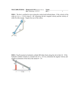
KINEMATICS OF RIGID BODIES Introduction In rigid body kinematics, we use the relationships governing the displacement, velocity and acceleration, but must also account for the rotational motion of the body. Description of the motion of rigid bodies is important for two reasons: 1) To generate, transmit or control motions by using cams, gears and linkages of various types and analyze the displacement, velocity and acceleration of the motion to determine the design geometry of the mechanical parts. Furthermore, as a result of the motion generated, forces may be developed which must be accounted for in the design of the parts. 2) To determine the motion of a rigid body caused by the forces applied to it. Calculation of the motion of a rocket under the influence of its thrust and gravitational attraction is an example of such a problem. Rigid Body Assumption A rigid body is a system of particles for which the distances between the particles and the angle between the lines remain unchanged. Thus, if each particle of such a body is located by a position vector from reference axes attached to and rotating with the body, there will be no change in any position vector as measured from these axes. Of course this is an idealization since all solid materials change shape to some extent when forces are applied to them. Nevertheless, if the movements associated with the changes in shape are very small compared with the movements of the body as a whole, then the assumption of rigidity is usually acceptable. Plane Motion All parts of the body move in parallel planes. The plane motion of a rigid body is divided into several categories: 1. Translation 2. Rotation 3. General Motion 1. TRANSLATION It is any motion in which every line in the body remains parallel to its original position at all times. In translation, there is no rotation of any line in the body. 1. Rectilinear Translation: All points in the body move in parallel straight lines. Rocket test sled 2. Curvilinear Translation: All points move on congruent curves. In each of the two cases of translation, the motion of the body is completely specified by the motion of any point in the body, since all the points have the same motion. 2. Fixed Axis Rotation Rotation about a fixed axis is the angular motion about the axis. All particles in a rigid body move in circular paths about the axis of rotation and all lines in the body which are perpendicular to the axis of rotation rotate through the same angle at the same time. A B C Aп‚ў Bп‚ў Cп‚ў 3. General Plane Motion It is the combination of translation and rotation. Aп‚ў A Bп‚ў B Crank (Krank) (Rotation) Piston (Translation) O w Connecting rod (General Motion) hinge Rotation The rotation of a rigid body is described by its angular motion. The figure shows a rigid body which is rotating as it undergoes plane motion in the plane of the figure. The angular positions of any two lines 1 and 2 attached to the body are specified by q1 and q2 measured from any convenient fixed reference direction. Because the angle b is invariant, the relation q2 = q1 + b upon differentiation with respect to time gives qпЂ¦2 пЂЅ qпЂ¦1 and qпЂ¦пЂ¦2 пЂЅ qпЂ¦пЂ¦1 during a finite interval, D q2 = D q1. All lines on a rigid body in its plane of motion have the same angular displacement, the same angular velocity and the same angular acceleration. Angular Motion Relations The angular velocity w and angular acceleration a of a rigid body in plane rotation are, respectively, the first and second time derivatives of the angular position coordinate q of any line in the plane of motion of the body. These definitions give dq пЂ¦ wпЂЅ пЂЅq dt dw aпЂЅ пЂЅ wпЂ¦ dt or П‰dП‰ пЂЅ О±dОё or aпЂЅ d 2q пЂЅ qпЂ¦пЂ¦ dt 2 qпЂ¦dqпЂ¦ пЂЅ qпЂ¦пЂ¦dОё For rotation with constant angular acceleration, the relationships become w пЂЅ w 0 пЂ« at w 2 пЂЅ w0 2 пЂ« 2a пЂЁq пЂ q 0 пЂ© 1 2 q пЂЅ q 0 пЂ« w 0 t пЂ« at 2 Rotation About a Fixed Axis When a rigid body rotates about a fixed axis, all points other than those on the axis move in concentric circles about the fixed axis. Thus, for the rigid body in the figure rotating about a fixed axis normal to the plane of the figure through O, any point such as A moves in a circle of radius r. So the velocity and the acceleration of point A can be written as v пЂЅ rw an пЂЅ rw 2 пЂЅ v 2 / r пЂЅ vw at пЂЅ ra These quantities may be expressed using the cross product пЃІ пЃІ пЃІ relationship of vector notation, w пЂЅ wk , a пЂЅ ak пЃІ пЃ¶ пЃ¶пЂ¦ пЃ¶ пЃ¶ v пЂЅ r пЂЅ wп‚ґr пЃІ пЃІ пЃІ пЃ¶ пЃ¶ пЃІ пЃІ d пЃІ d пЃ¶ пЃІ dw пЃІ пЃ¶ dr a пЂЅ пЂЁv пЂ© пЂЅ пЂЁw п‚ґ r пЂ© пЂЅ п‚ґr пЂ«wп‚ґ пЂЅa п‚ґ r пЂ« w п‚ґ пЂЁw п‚ґ r пЂ© пЃ» пЂ±пЂґпЂІ пЂґпЂі пЃІ dt dt dt dt пЃІ at пЃ» пЃ» пЃ¶ пЃ¶ a пЃІ пЃ¶ пЃІ v пЂЅwп‚ґr an PROBLEMS 1. The angular velocity of a gear is controlled according to w = 12 – 3t2, where w in rad/s and t is the time in seconds. Find the net angular displacement Dq from the time t = 0 to t = 3 s. Also find the total number of revolutions N through which the gear turns during the three seconds. SOLUTION dq пЂЅw dt q пѓІ dq пЂЅ 0 dq пЂЅ wdt пѓћ пѓІ пЂЁ12 пЂ 3t пЂ©dt 3 2 0 Dq пЂЅ 9 rad 3 , 3 3 q пЂЅ 12t пЂ t пЂЅ 12пЂЁ3пЂ© пЂ 33 пЂЅ 9 rad 3 0 SOLUTION Does the gear stop between t = 0 and t = 3 seconds? w пЂЅ 12 пЂ 3t 2 пЂЅ 0 q1 пѓІ dq пЂЅ 0 12 пЂЅ 3t 2 t пЂЅ 2 s (it stops at t пЂЅ 2 s ) пѓІ пЂЁ12 пЂ 3t пЂ©dt 2 2 2 пѓћ 3 q1 пЂЅ 12t пЂ t 3 пЂЅ 12пЂЁ2пЂ© пЂ 23 пЂЅ 16 rad 3 0 пѓћ 3 q 2 пЂЅ 12t пЂ t 3 3 0 q2 пѓІ 0 dq пЂЅ пѓІ пЂЁ12 пЂ 3t пЂ©dt 3 2 2 3 пЂЅ пЂ7 rad 2 16 пЂ« пЂ 7 пЂЅ 23 rad 1 revolution 2пЃ° rad N revolutions 23 rad пѓћ N пЂЅ 3.66 revolutions PROBLEMS 2. The belt-driven pulley and attached disk are rotating with increasing angular velocity. At a certain instant the speed v of the belt is 1.5 m/s, and the total acceleration of point A is 75 m/s2. For this instant determine (a) the angular acceleration a of the pulley and disk, (b) the total acceleration of point B, and (c) the acceleration of point C on the belt. SOLUTION vC пЂЅ 1.5 m / s wпЂЅ a A пЂЅ 75 m / s 2 a) a пЂЅ ? b) a B пЂЅ ? c) a C пЂЅ ? vC 1.5 пЂЅ пЂЅ 20 rad / s r 0.075 a An пЂЅ w 2 R пЂЅ 20 2 0.15 пЂЅ 60 m / s 2 a At пЂЅ 75 2 пЂ 60 2 пЂЅ 45 m / s 2 aпЂЅ a At R пЂЅ 45 пЂЅ 300 rad / s 2 0.15 a Bt пЂЅ a пѓ— r пЂЅ 300 пѓ— 0.075 пЂЅ 22.5 m / s 2 a Bn пЂЅ w 2 пѓ— r пЂЅ 20 2 пѓ— 0.075 пЂЅ 30 m / s 2 aC пЂЅ a пѓ— r пЂЅ 300 пѓ— 0.075 пЂЅ 22.5 m / s 2 пѓј пѓЇ 2 2 2 пѓЅ a B пЂЅ 22.5 пЂ« 30 пЂЅ 37.5 m / s пѓЇпѓѕ PROBLEMS 3. The design characteristics of a gear-reduction unit are under review. Gear B is rotating clockwise (cw) with a speed of 300 rev/min when a torque is applied to gear A at time t=2 s to give gear A a counterclockwise (ccw) acceleration a which varies with time for a duration of 4 seconds as shown. Determine the speed NB of gear B when t=6 s. SOLUTION tпЂЅ2 s пѓћ N B пЂЅ 300 rev / min w B пЂЅ 300 пѓ— 2пЃ° пЂЅ 10пЃ° rad / s 60 The velocities of gears A and B are same at the contact point. w A пЂЁb пЂ© пЂЅ w B пЂЁ2b пЂ© пѓћ v A пЂЅ vB пѓћ aA пЂЅ t пЂ«2 w A пЂ 20пЃ° пЂЅ t пЂЅ6 s пѓћ пѓћ 2 t пЂ« 2t 2 aA пЂЅ dw A dt w A пЂЅ 20пЃ° rad / s wA пѓћ пѓІпЃ°dw 20 6 A пЂЅ пѓІ пЂЁt пЂ« 2пЂ©dt t пЂЅ2 6 пѓћ w A пЂЅ 86.83 rad / s (at t пЂЅ 6 s) 2 w A пЂЁb пЂ© пЂЅ w B пЂЁ2b пЂ© пѓћ w B пЂЅ 43.415 rad / s N B пЂЅ 414.59 rev / min Absolute Motion In this approach, we make use of the geometric relations which define the configuration of the body involved and then proceed to take the time derivatives of the defining geometric relations to obtain velocities and accelerations. PROBLEM 1) A wheel of radius r rolls on a flat surface without slipping. Determine the angular motion of the wheel in terms of the linear motion of its center O. Also determine the acceleration of a point on the rim of the wheel as the point comes into contact with the surface on which the wheel rolls. PROBLEM 2) Motion of the equilateral triangular plate ABC in its plane is controlled by the hydraulic cylinder D. If the piston rod in the cylinder is moving upward at the constant rate of 0.3 m/s during an interval of its motion, calculate for the instant when q=30o the velocity and acceleration of the center of the roller B in the horizontal guide and the angular velocity and angular acceleration of edge CB. PROBLEM 3) Derive an expression for the upward velocity v of the car hoist in terms of q. The piston rod of the hydraulic cylinder is extending at the rate sпЂ¦ . PROBLEM 4) Calculate the angular velocity w of the slender bar AB as a fuction of the distance x and the constant angular velocity wo of the drum. Relative Motion The second approach to rigid body kinematics uses the principles of relative motion. In kinematics of particles for motion relative to translating axes, we applied the relative velocity equation пЃ¶ пЃ¶ пЃ¶ v A пЂЅ vB пЂ« v A / B to the motions of two particles A and B. We now choose two points on the same rigid body for our two particles. The consequence of this choice is that the motion of one point as seen by an observer translating with the other point must be circular since the radial distance to the observed point from the reference point does not change. The figure shows a rigid body moving in the plane of the figure from position AB to AВґBВґ during time Dt. This movement may be visualized as occurring in two parts. First, the body translates to the parallel пЃ¶ position AВґВґBВґ with the displacement DrB . Second, the body rotates about BВґ through the angle Dq, from the nonrotating reference axes xВґ-yВґ attached to the reference point BВґ, giving rise to the пЃ¶ displacement DrA / B of A with respect to B. пЃ¶ DrA / B With B as the reference point, the total displacement of A is пЃ¶ пЃ¶ пЃ¶ DrA пЂЅ DrB пЂ« DrA / B пЃ¶ Where DrA / B has the magnitude rDq as Dq approaches zero. Dividing the time interval relative velocity equation Dt and passing to the limit, we obtain the пЃ¶ пЃ¶ пЃ¶ v A пЂЅ vB пЂ« v A / B The distance r between A and B remains constant. The magnitude of the relative velocity is thus seen to be пЃ¶ пѓ¦ DrA / B пѓ¶ dq пѓ¦ rDq пѓ¶ пѓ§ пѓ· v A / B пЂЅ lim пЂЅ lim пѓ§ пЂЅr пѓ· пѓ· Dt п‚®0 пѓЁ Dt пѓё Dt п‚®0 пѓ§ D t dt пѓЁ пѓё which, with w пЂЅ qпЂ¦ becomes v A / B пЂЅ rw пЃ¶ пЃ¶ Using r to represent the vector rA / B , we may write the relative velocity as the vector пЃ¶ пЃ¶ пЃ¶ vA/ B пЂЅ w п‚ґ r Therefore, the relative velocity equation becomes пЃ¶ пЃ¶ пЃ¶ пЃ¶ v A пЂЅ vB пЂ« w п‚ґ r Here, пЃ¶ w is the angular velocity vector normal to the plane of the motion in the sense determined by the right hand rule. It should be noted that the direction of the relative velocity will always be perpendicular to the line joining the points A and B. Interpretation of the Relative Velocity Equation We can better understand the relative velocity equation by visualizing the translation and rotation components separately. Translation Fixed axid rotation In the figure, point B is chosen as the reference point and the пЃ¶ velocity of A is the vector sum of the translational portion v B , plus пЃ¶ пЃ¶ пЃ¶ vA/ B пЂЅ w п‚ґ r the rotational portion , which has the magnitude пЃ¶ vA/B=rw, where w пЂЅ qпЂ¦ , the absolute angular velocity of AB . The relative linear velocity is always perpendicular to the line joining the two points A and B. Relative Acceleration Equation of relative velocity is пЃ¶ пЃ¶ пЃ¶ v A пЂЅ vB пЂ« v A / B By differentiating the equation with respect to time, we obtain the relative acceleration equation, which is or пЃ¶пЂ¦ пЃ¶пЂ¦ пЃ¶пЂ¦ v A пЂЅ vB пЂ« v A / B пЃ¶ пЃ¶ пЃ¶ a A пЂЅ aB пЂ« a A / B This equation states that the acceleration of point A equals the vector sum of the acceleration of point B and the acceleration which A appears to have to a nonrotating observer moving with B. If points A and B are located on the same rigid body, the distance r between them remains constant. Because the relative motion is circular, the relative acceleration term will have both a normal component directed from A toward B due to the change of direction пЃ¶ of v A / B and a tangential component perpendicular to AB due to the пЃ¶ v change in magnitude of A / B . Thus, we may write, пЃ¶ пЃ¶ пЃ¶ пЃ¶ a A пЂЅ aB пЂ« пЂЁa A / B пЂ©n пЂ« пЂЁa A / B пЂ©t Where the magnitudes of the relative acceleration components are пЂЁa A / B пЂ©n пЂЅ v A / B 2 / r пЂЅ rw 2 пЂЁa A / B пЂ©t пЂЅ vпЂ¦ A / B пЂЅ ra In vector notation the acceleration components are пЃ¶ пЃ¶ пЃ¶ пЃ¶ пЂЁa A / B пЂ©n пЂЅ w п‚ґ пЂЁw п‚ґ r пЂ© пЃ¶ пЃ¶ пЃ¶ пЂЁa A / B пЂ©t пЂЅ a п‚ґ r The relative acceleration equation, thus, becomes пЃ¶ пЃ¶ пЃ¶ пЃ¶ пЃ¶ пЃ¶ пЃ¶ a A пЂЅ aB пЂ« w п‚ґ пЂЁw п‚ґ r пЂ© пЂ« a п‚ґ r The figure shows the acceleration of A to be composed of two parts: the acceleration of B and the acceleration of A with respect to B. Solution of the Relative Acceleration Equation As in the case of the relative velocity equation, the relative acceleration equation may be carried out by scalar or vector algebra or by graphical construction. Because the normal acceleration components depend on velocities, it is generally necessary to solve for the velocities before the acceleration calculations can be made. PROBLEMS 1. The center O of the disk has the velocity and acceleration shown. If the disk rolls without slipping on the horizontal surface, determine the velocity of A and the acceleration of B for the instant represented. PROBLEMS 2. If the velocity of point A is 3 m/s to the right and is constant for an interval including the position shown, determine the tangential acceleration of point B along its path and the angular acceleration of the bar AB. PROBLEMS 3. The flexible band F attached to the sector at E is given a constant velocity of 4 m/s as shown. For the instant when BD is perpendicular to OA, determine the angular acceleration of BD. PROBLEMS 4. A mechanism for pushing small boxes from an assembly line onto a conveyor belt is shown with arm OD and crank CB in their vertical positions. For the configuration shown, crank CB has a constant clockwise angular velocity of пЃ° rad/s. Determine the acceleration of E. PROBLEMS 5. At a given instant, the gear has the angular motion shown. Determine the acceleration of points A and B on the link and the link’s angular accelartion at this instant. PROBLEMS 6. The center O of the disk rolling without slipping on the horizontal surface has the velocity and acceleration shown. Radius of the disk is 4.5 cm. Calculate the velocity and acceleration of point B. vo=45 cm/s O 37o A y 4.5 cm 6 cm B 1 y пЂЅ x2 4 4 cm x x=2 cm 10 cm ao=90 cm/s2
© Copyright 2026 Paperzz