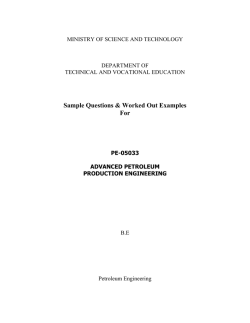
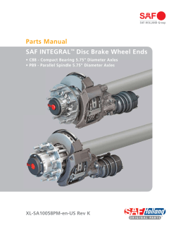
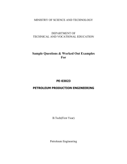
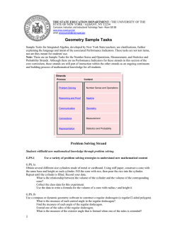
www.swagelok.com C o n e an d Th read Fittings and Adapters — S p eci a l Al l oy M at erials IPT Series ■Excellent corrosion resistance in chloride-containing environments ■Manufactured to meet NACE MR0175/ISO 15156 and NORSOK ■Medium-pressure fittings—up to 20 000 psig (1378 bar); sizes 1/4 to 1 in. ■High-pressure fittings—up to 40 000 psig (2756 bar); sizes 1/4 to 9/16 in. ■Temperature range: –58 to 482°F (–50 to 250°C) 2 Cone and Thread Fittings and Adapters—Special Alloy Materials Contents Cone and Thread Fittings— IPT Series Features, 3 Pressure Ratings, 3 Adapters—IPT Series Installation Instructions Features, 7 ■Medium-Pressure Cone and Thread Fitting Assembly, 17 Materials of Construction, 7 Materials of Construction, 3 Pressure Ratings, 7 Cleaning and Packaging, 3 Cleaning and Packaging, 7 Dimensions—Cone & Thread End Connections, 4 Ordering Information Ordering Information and Dimensions Male to Male NPT, 8 Couplings, Elbows, Tees, 4 Crosses, Bulkheads, 5 Medium-Pressure Cone and Thread, 9 High-Pressure Cone and Thread, 9 Caps and Plugs, 6 Female to Female NPT, 10 Collars and Glands, 6 Medium-Pressure Cone and Thread, 11 High-Pressure Cone and Thread, 12 Male to Female NPT, 13 Medium-Pressure Cone and Thread, 14 High-Pressure Cone and Thread, 16 ■High-Pressure Cone and Thread Fitting Assembly, 17 Cone and Thread Fittings and Adapters—Special Alloy Materials 3 SAF 2507™ Cone and Thread Fittings—IPT Series Elevated Temperature Factors To determine allowable working pressure at elevated temperatures, multiply allowable working pressures by a factor shown below. Temperature °C Factor Annealed SAF 2507 –58 to 0 –50 to –17 1.00 0 to 200 –17 to 93 0.90 300 148 0.85 400 204 0.82 482 250 0.81 °F Features ■All C&T adapters and couplings are manufactured to meet NACE MR0175/ISO 15156 and NORSOK. ■Sizes available: ■Medium-pressure—1/4 to to 1 in. Materials of Construction ■High-pressure—1/4 to 9/16 in. ■Annealed SAF 2507 Pressure Ratings Pressure ratings are dependent on the end connection or system component with the lowest pressure rating. Working pressure determined based on ASME B31.3 Process Piping, Chapter IX High Pressure Piping calculations. Ratings apply to SAF 2507 cone and thread fittings with collars and glands manufactured from either annealed SAF 2507 or strainhardened 316 stainless steel. ■Medium-pressure cone and thread end connections are rated to 20 000 psig (1378 bar). ■High-pressure cone and thread end connections are rated Component Material/ASTM Specification Body SAF 2507/A789 Gland SAF 2507/A789 Collar SAF 2507/A789 Wetted components listed in italics. Cleaning and Packaging All cone and thread fittings are cleaned in accordance with Swagelok Standard Cleaning and Packaging (SC‑10), MS‑06‑62. to 40 000 psig (2756 bar). SAF 2507 Cone and Thread Fitting—IPT Series Medium-pressure cone and thread end connection shown on left side of fitting Fitting body Primary seal surface Gland creates a load on the collar to ensure a seal on the tubing and body angle area. High-pressure cone and thread end connection shown on right side of fitting Weep hole enables leak detection and verification of a proper installation. Collar threads onto the cone and thread tubing with left-hand threads to prevent accidental disassembly of collar during installtion. Cone and thread tubing is required for cone and thread fitting installation. High-pressure tubing has a thicker wall than medium-pressure tubing. 4 Cone and Thread Fittings and Adapters—Special Alloy Materials Dimensions—Cone & Thread End Connections Dimensions are for reference only and are subject to change. D C B Female pocket Female seat A 5° Weep hole E F H Male coned tube 60° 59° G 45° Dimensions, in. (mm) Fitting Size in. A B C D E Medium Pressure: 20 000 psig (1378 bar) F G H Tube Engagement Length 1/4-28 0.056 (14.2) 3/8-24 0.69 (17.5) 1/4 0.39 (9.9) 7/16-20 0.28 (7.1) 0.50 (12.7) 0.11 (2.8) 0.19 (4.6) 0.14 (3.6) 0.63 (16.0) 0.20 (5.1) 0.31 (7.9) 0.25 (6.4) 3/8 0.52 (13.2) 9/16-18 0.38 (9.7) 9/16 0.75 (19.0) 13/16-16 0.44 (11.2) 0.75 (19.0) 0.31 (7.9) 0.50 (12.7) 0.41 (10.4) 9/16-18 0.84 (21.3) 3/4 0.95 (24.1) 3/4-14 NPSM 0.70 (17.8) 0.94 (23.9) 0.44 (11.2) 0.63 (16.0) 0.56 (14.2) 3/4-16 1.00 (25.4) 1-14 1.47 (37.3) 1 1.30 (33.0) 1 3/8-12 0.81 (20.6) 1.31 (33.3) 0.56 (14.2) 0.88 (22.4) 0.72 (18.3) High Pressure: 40 000 psig (2756 bar) 1/4 0.52 (13.2) 9/16-18 0.38 (9.7) 0.44 (11.2) 0.09 (2.3) 0.17 (4.3) 0.13 (3.3) 1/4-28 0.50 (12.7) 3/8 0.69 (17.5) 3/4-16 0.53 (13.5) 0.63 (16.0) 0.13 (3.3) 0.27 (6.9) 0.22 (5.6) 3/8-24 0.69 (17.5) 9/16 1.05 (26.7) 1 1/8-12 0.62 (15.7) 0.75 (19.0) 0.19 (4.6) 0.38 (9.7) 0.28 (7.1) 9/16-18 0.88 (22.4) Ordering Information and Dimensions ■Dimensions are for reference only and are subject to change. ■Collar and glands are shown for dimensional purposes only; dimensions are shown with cone and thread glands finger-tight. ■2507-NACE cone and thread fittings are not supplied with collars and glands. Collar and glands must be ordered separately. See page 6. Ordering Information Select a basic ordering number from a Dimensions table and add 2507-NACE as a suffix. Examples: Coupling—CN6MF20-2507-NACE Collar—CL4M-2507-NACE High Pressure Medium Pressure Couplings C G flat A F flat C G flat F flat A Tube OD in. 1/4 3/8 9/16 3/4 1 Basic Dimensions, in. (mm) Ordering Number A C F Medium Pressure: 20 000 psig (1378 bar) CN4MF201.50 (38.1) 0.38 (9.7) 3/4 CN6MF201.75 (44.5) 0.48 (12.2) 3/4 CN9MF202.12 (53.8) 0.68 (17.3) 1 CN12MF202.50 (63.5) 0.59 (15.0) 1 3/8 CN16MF203.50 (88.9) 0.74 (18.8) 1 3/4 1/2 5/8 7/8 1 3/16 1 3/8 1/4 3/8 9/16 High Pressure: 40 000 psig (2756 bar) CN4HF401.38 (35.1) 0.59 (15.0) 3/4 CN6HF401.75 (44.5) 0.72 (18.3) 1 CN9HF402.25 (57.2) 1.00 (25.4) 1 3/8 5/8 13/16 1 3/16 G Cone and Thread Fittings and Adapters—Special Alloy Materials 5 Elbows A C Tube OD in. Medium Pressure B E D A High Pressure C 1/4 3/8 9/16 Tube OD in. Basic Ordering Number B D E Dimensions, in. (mm) A B C D E F G Medium Pressure: 20 000 psig (1378 bar) L4MF20- 1.50 (38.1) 0.75 (19.1) 0.38 (9.7) 0.75 (19.1) 1.13 (28.6) 5/8 1/2 L6MF20- 2.00 (50.8) 1.00 (25.4) 0.48 (12.2) 1.00 (25.4) 1.38 (35.1) 3/4 5/8 L9MF20- 2.50 (63.5) 1.25 (31.8) 0.68 (17.3) 1.25 (31.8) 1.75 (44.5) 1 7/8 L12MF20- 3.00 (76.2) 1.50 (38.1) 0.59 (15) 1.50 (38.1) 2.25 (57.2) 1 3/8 1 3/16 L16MF20- 4.13 (105) 2.06 (52.3) 0.74 (18.8) 2.06 (52.3) 3.00 (76.2) 1 3/4 1 3/8 High Pressure: 40 000 psig (2756 bar) L4HF40- 1.50 (38.1) 0.88 (22.4) 0.59 (15) 0.63 (15.9) 1.00 (25.4) 1 5/8 L6HF40- 2.00 (50.8) 1.25 (31.8) 0.72 (18.3) 1.00 (25.4) 1.50 (38.1) 1 13/16 L9HF40- 2.62 (66.5) 1.88 (47.6) 1.00 (25.4) 1.13 (28.6) 1.88 (47.6) 1 1/2 1 3/16 1/4 3/8 9/16 3/4 1 F flat G flat Basic Ordering Number F flat G flat Tees C A Medium Pressure B D F flat G flat High Pressure C B 1/4 3/8 9/16 A B C D E F G Medium Pressure: 20 000 psig (1378 bar) T4MF20- 1.50 (38.1) 0.75 (19.1) 0.38 (9.7) 0.75 (19.1) 1.13 (28.6) 5/8 1/2 T6MF20- 2.00 (50.8) 1.00 (25.4) 0.48 (12.2) 1.00 (25.4) 1.38 (35.1) 3/4 5/8 T9MF20- 2.50 (63.5) 1.25 (31.8) 0.68 (17.3) 1.25 (31.8) 1.75 (44.5) 1 7/8 T12MF20- 3.00 (76.2) 1.50 (38.1) 0.59 (15) 1.50 (38.1) 2.25 (57.2) 1 3/8 1 3/16 T16MF20- 4.12 (105) 2.06 (52.3) 0.74 (18.8) 2.06 (52.3) 3.00 (76.2) 1 3/4 1 3/8 High Pressure: 40 000 psig (2756 bar) T4HF40- 2.00 (50.8) 1.00 (25.4) 0.59 (15) 0.88 (22.4) 1.25 (31.8) 1 5/8 T6HF40- 2.00 (50.8) 1.00 (25.4) 0.72 (18.3) 1.06 (27.0) 1.56 (39.6) 1 13/16 T9HF40- 2.62 (66.5) 1.31 (33.3) 1.00 (25.4) 1.38 (34.9) 2.12 (53.8) 1 1/2 1 3/16 Tube OD in. Basic Ordering Number 1/4 3/8 9/16 3/4 1 E Dimensions, in. (mm) A D E F flat G flat Crosses Medium Pressure C B A D E G flat F flat High Pressure C B A 1/4 3/8 9/16 3/4 1 1/4 3/8 D 9/16 E G flat F flat Dimensions, in. (mm) A B C D E F G Medium Pressure: 20 000 psig (1378 bar) X4MF20- 1.50 (38.1) 0.75 (19.1) 0.38 (9.7) 0.75 (19.1) 1.50 (38.1) 5/8 1/2 X6MF20- 2.00 (50.8) 1.00 (25.4) 0.48 (12.2) 1.00 (25.4) 2.00 (50.8) 3/4 5/8 X9MF20- 2.50 (63.5) 1.25 (31.8) 0.68 (17.3) 1.25 (31.8) 2.50 (63.5) 1 7/8 X12MF20- 3.00 (76.2) 1.50 (38.1) 0.59 (15) 1.50 (38.1) 3.00 (76.2) 1 3/8 1 3/16 X16MF20- 4.12 (105) 2.06 (52.3) 0.74 (18.8) 2.06 (52.3) 4.12 (105) 1 3/4 1 3/8 High Pressure: 40 000 psig (2756 bar) X4HF40- 2.00 (50.8) 1.00 (25.4) 0.59 (15.0) 0.63 (16.0) 1.25 (31.8) 1 5/8 X6HF40- 2.00 (50.8) 1.00 (25.4) 0.72 (18.3) 1.06 (27.0) 2.12 (53.8) 1 13/16 X9HF40- 2.62 (66.5) 1.31 (33.3) 1.00 (25.4) 1.38 (34.9) 2.75 (69.8) 1 1/2 1 3/16 6 Cone and Thread Fittings and Adapters—Special Alloy Materials Medium Pressure Bulkheads C F flat High Pressure Tube OD in. Gx flat C F flat Dimensions, in. (mm) A G flat A G flat Gx flat 1/4 3/8 9/16 3/4 1 1/4 3/8 9/16 Basic Ordering Number A Medium BH4MF20- 2.00 (50.8) BH6MF20- 2.00 (50.8) BH9MF20- 2.62 (66.5) BH12MF20- 2.62 (66.5) BH16MF20- 3.50 (88.9) BH4HF40BH6HF40BH9HF40- C F G Gx Pressure: 20 000 psig (1378 bar) 0.38 (9.7) 1 1/2 1 0.48 (12.2) 1 5/8 1 0.68 (17.3) 1 3/8 7/8 1 3/8 0.59 (15) 1 7/8 1 3/16 1 7/8 0.74 (18.8) 2 1/8 1 3/8 2 1/8 Panel Panel Thickness Hole Size Max 0.88 0.94 1.25 1.69 2.00 (22.4) 0.38 (9.7) (23.9) 0.38 (9.7) (31.8) 0.50 (12.7) (42.9) 0.38 (9.7) (50.8) 0.50 (12.7) High Pressure: 40 000 psig (2756 bar) 2.00 (50.8) 0.59 (15.0) 1 5/8 1 0.94 (23.9) 0.50 (12.7) 2.38 (40.5) 0.72 (18.3) 1 3/8 13/16 1 3/8 1.12 (28.4) 0.38 (9.7) 2.75 (69.9) 1.00 (25.4) 1 7/8 1 3/16 1 7/8 1.75 (44.5) 0.62 (15.7) Caps and Plugs Caps A Plugs C A D G flat F flat Tube OD in. Medium-pressure configuration shown 1/4 3/8 9/16 3/4 1 Basic Dimensions, in. (mm) Ordering Number A C F Medium Pressure: 20 000 psig (1378 bar) CA4M201.00 (25.4) 0.38 (9.7) 5/8 CA6M201.25 (31.8) 0.48 (12.2) 3/4 CA9M201.50 (38.1) 0.68 (17.3) 1 CA12M201.75 (44.5) 0.59 (15) 1 3/8 CA16M202.25 (57.2) 0.74 (18.8) 1 3/4 1/2 5/8 7/8 1 3/16 1 3/8 Tube Basic Dimensions, in. (mm) OD Ordering in. Number A D Medium Pressure: 20 000 psig (1378 bar) 1/4 PL4M1.00 (25.4) 0.25 (6.4) 3/8 PL6M1.25 (31.8) 0.38 (9.5) 9/16 PL9M1.56 (39.6) 0.56 (14.2) 3/4 PL12M1.62 (41.2) 0.75 (19.5) 1 PL16M2.19 (55.6) 1.00 (25.4) 1/4 3/8 9/16 High Pressure: 40 000 psig (2756 bar) CA4H401.06 (27.0) 0.59 (15) 3/4 CA6H401.25 (31.8) 0.72 (18.3) 1 CA9H401.62 (41.2) 1.00 (25.4) 1 3/8 5/8 13/16 1 3/16 High 1/4 3/8 9/16 G Pressure: 40 000 psig (2756 bar) PL4H1.16 (29.4) 0.25 (6.4) PL6H1.56 (39.6) 0.38 (9.5) PL9H2.00 (50.8) 0.56 (14.2) Collars and Glands Collars Glands Basic Ordering Number Tube OD Antivibration in. Collar Gland Gland Medium Pressure: 20 000 psig (1378 bar) 1/4 CL4MGL4MAV4M3/8 CL6MGL6MAV6M9/16 CL9MGL9MAV9M3/4 CL12MGL12MAV12M1 CL16MGL16MAV16MHigh Pressure: 40 000 psig (2756 bar) 1/4 CL4HGL4HAV4H3/8 CL6HGL6HAV6H9/16 CL9HGL9HAV9H- Antivibration Glands Medium Pressure High Pressure To order collars and glands in 316 stainless steel, see the Swagelok Medium- and High-Pressure Fittings, Tubing, Valves, and Accessories catalog, MS-02-472-E. Cone and Thread Fittings and Adapters—Special Alloy Materials 7 SAF 2507 Cone and Thread Adapters and Couplings—IPT Series Features Pressure Ratings ■End connections types include Pressure ratings are dependent on the end connection or system component with the lowest pressure rating. Working pressure determined based on ASME B31.3 Process Piping, Chapter IX High Pressure Piping calculations. Ratings apply to SAF 2507 cone and thread fittings with collars and glands manufactured from either annealed SAF 2507 or strainhardened 316 stainless steel. ■NPT ■Medium-pressure cone and thread (C&T) ■High-pressure cone and thread (C&T). ■All C&T adapters and couplings are manufactured to meet NACE MR0175/ISO 15156 and NORSOK. ■Sizes available: ■Medium-pressure cone and thread end connections are rated to 20 000 psig (1378 bar). ■High-pressure cone and thread end connections are rated ■Medium-pressure—1/4 to to 1 in. to 40 000 psig (2756 bar). ■High-pressure—1/4 to 9/16 in. ■C&T adapters and couplings are available in one piece design only. One-piece Design Integral cone end Elevated Temperature Factors To determine allowable working pressure at elevated temperatures, multiply allowable working pressures by a factor shown below. Temperature °C Factor Annealed SAF 2507 –58 to 0 –50 to –17 1.00 0 to 200 –17 to 93 0.90 300 148 0.85 400 204 0.82 482 250 0.81 °F ■One-piece design is standard ■Features integral cone end on body for ease of assembly. Materials of Construction ■Annealed SAF 2507 Component Material/ASTM Specification Body SAF 2507/A789 Gland SAF 2507/A789 Collar SAF 2507/A789 Wetted components listed in italics. Cleaning and Packaging All cone and thread adapters and couplings are cleaned in accordance with Swagelok Standard Cleaning and Packaging (SC‑10), MS‑06‑62. 8 Cone and Thread Fittings and Adapters—Special Alloy Materials Ordering Information Select a basic ordering number from a Ordering Information table, and add 2507-NACE as a suffix. Example: CN6MM4HF20-2507-NACE ■2507-NACE cone and thread fittings are not supplied with collars and glands. Collar and glands must be ordered separately. See page 6. Male-to-Male Adapters and Couplings Male NPT to Medium-Pressure Cone and Thread Male NPT Male NPT Size in. 1/4 3/8 1/2 3/4 1 MediumPressure C&T Size in. Male NPT to High-Pressure Cone and Thread Medium-pressure C&T Basic Ordering Number 1/4 CN4NM4MM15- 3/8 CN4NM6MM15- 9/16 CN4NM9MM15- 3/4 CN4NM12MM15- 1 CN4NM16MM15- 1/4 CN6NM4MM15- 3/8 CN6NM6MM15- 9/16 CN6NM9MM15- 3/4 CN6NM12MM15- 1 CN6NM16MM15- 1/4 CN8NM4MM15- 3/8 CN8NM6MM15- 9/16 CN8NM9MM15- 3/4 CN8NM12MM15- 1 CN8NM16MM15- 1/4 CN12NM4MM10- 3/8 CN12NM6MM10- 9/16 CN12NM9MM10- 3/4 CN12NM12MM10- 1 CN12NM16MM10- 1/4 CN16NM4MM10- 3/8 CN16NM6MM10- 9/16 CN16NM9MM10- 3/4 CN16NM12MM10- 1 CN16NM16MM10- Pressure Ratings SAF 2507 psig (bar) 15 000 Male NPT Male NPT Size in. 1/4 (1034) 3/8 15 000 (1034) 1/2 3/4 15 000 (1034) 10 000 (689) 10 000 (689) 1 HighPressure C&T Size in. High-pressure C&T Basic Ordering Number 1/4 CN4NM4HM15- 3/8 CN4NM6HM15- 9/16 CN4NM9HM15- 1/4 CN6NM4HM15- 3/8 CN6NM6HM15- 9/16 CN6NM9HM15- 1/4 CN8NM4HM15- 3/8 CN8NM6HM15- 9/16 CN8NM9HM15- 1/4 CN12NM4HM10- 3/8 CN12NM6HM10- 9/16 CN12NM9HM10- 1/4 CN16NM4HM10- 3/8 CN16NM6HM10- 9/16 CN16NM9HM10- Pressure Ratings SAF 2507 psig (bar) 15 000 (1034) 15 000 (1034) 15 000 (1034) 10 000 (689) 10 000 (689) Cone and Thread Fittings and Adapters—Special Alloy Materials 9 Male-to-Male Adapters and Couplings Medium-Pressure Cone and Thread to Medium-Pressure Cone and Thread Medium-pressure C&T MediumPressure C&T Size in. 1/4 3/8 9/16 3/4 1 MediumPressure C&T Size in. Medium-pressure C&T Basic Ordering Numberr 1/4 CN4MM20- 3/8 CN4MM6MM20- 9/16 CN4MM9MM20- 3/4 CN4MM12MM20- 1 CN4MM16MM20- 3/8 CN6MM20- 9/16 CN6MM9MM20- 3/4 CN6MM12MM20- 1 CN6MM16MM20- 9/16 CN9MM20- 3/4 CN9MM12MM20- 1 CN9MM16MM20- 3/4 1 1 Medium-Pressure Cone and Thread to High-Pressure Cone and Thread CN12MM20CN12MM16MM20CN16MM20- Pressure Ratings SAF 2507 psig (bar) 20 000 Medium-pressure C&T MediumPressure C&T Size in. 1/4 (1378) 3/8 20 000 (1378) 20 000 (1378) 9/16 3/4 20 000 (1378) 1 20 000 HighPressure C&T Size in. High-pressure C&T Pressure Ratings SAF 2507 psig (bar) Basic Ordering Number 1/4 CN4MM4HM20- 3/8 CN4MM6HM20- 9/16 CN4MM9HM20- 1/4 CN6MM4HM20- 3/8 CN6MM6HM20- 9/16 CN6MM9HM20- 1/4 CN9MM4HM20- 3/8 CN9MM6HM20- 9/16 CN9MM9HM20- 1/4 CN12MM4HM20- 3/8 CN12MM6HM20- 9/16 CN12MM9HM20- 1/4 CN16MM4HM20- 3/8 CN16MM6HM20- 9/16 CN16MM9HM20- 20 000 (1378) 20 000 (1378) 20 000 (1378) 20 000 (1378) 20 000 (1378) (1378) High-Pressure Cone and Thread to High-Pressure Cone and Thread High-pressure C&T HighPressure C&T Size in. 1/4 3/8 9/16 HighPressure C&T Size in. High-pressure C&T Basic Ordering Number 1/4 CN4HM40- 3/8 CN4HM6HM40- 9/16 CN4HM9HM40- 3/8 CN6HM40- 9/16 CN6HM9HM40- 9/16 CN9HM40- Pressure Ratings SAF 2507 psig (bar) 40 000 (4134) 40 000 (4134) 40 000 (4134) Cone and Thread Fittings and Adapters—Special Alloy Materials 10 Female-to-Female Adapters and Couplings Female NPT to Female NPT Female NPT Female NPT Size in. 1/4 3/8 1/2 3/4 1 Female NPT to Medium-Pressure Cone and Thread Female NPT Female NPT Size in. Basic Ordering Number Female NPT Pressure Ratings SAF 2507 psig (bar) Female NPT Size in. Medium-pressure C&T MediumPressure C&T Size in. Basic Ordering Number 1/4 CN4NF15- 3/8 CN4NF6NF15- 1/2 CN4NF8NF15- 3/4 CN4NF12NF10- 10 000 1 CN4NF16NF10- (689) 1 CN4NF16MF15- 15 000 1/4 CN6NF4MF15- 15 000 (1034) 3/8 CN6NF15- 1/2 CN6NF8NF15- 3/4 CN6NF12NF10- 10 000 1 CN6NF16NF10- (689) (1034) CN8NF15- 3/4 CN8NF12NF10- 10 000 1 CN8NF16NF10- (689) 1 1 CN12NF10CN12NF16NF10CN16NF10- 3/8 15 000 1/2 3/4 1/4 (1034) 1/2 10 000 (689) 10 000 (689) 3/4 1 1/4 CN4NF4MF15- 3/8 CN4NF6MF15- 9/16 CN4NF9MF15- 3/4 CN4NF12MF15- 3/8 CN6NF6MF15- 9/16 CN6NF9MF15- 3/4 CN6NF12MF15- 1 CN6NF16MF15- 1/4 CN8NF4MF15- 3/8 CN8NF6MF15- 9/16 CN8NF9MF15- 3/4 CN8NF12MF15- 1 CN8NF16MF15- 1/4 CN12NF4MF10- 3/8 CN12NF6MF10- 9/16 CN12NF9MF10- 3/4 CN12NF12MF10- 1 CN12NF16MF10- 1/4 CN16NF4MF10- 3/8 CN16NF6MF10- 9/16 CN16NF9MF10- 3/4 CN16NF12MF10- 1 CN16NF16MF10- Pressure Ratings SAF 2507 psig (bar) 15 000 (1034) 15 000 (1034) 15 000 (1034) 10 000 (689) 10 000 (689) Cone and Thread Fittings and Adapters—Special Alloy Materials 11 Female-to-Female Adapters and Couplings Female NPT to High-Pressure Cone and Thread Female NPT Female NPT Size in. 1/4 3/8 1/2 3/4 1 HP C&T Size in. High-pressure C&T Basic Ordering Number 1/4 CN4NF4HF15- 3/8 CN4NF6HF15- 9/16 CN4NF9HF15- 1/4 CN6NF4HF15- 3/8 CN6NF6HF15- 9/16 CN6NF9HF15- 1/4 CN8NF4HF15- 3/8 CN8NF6HF15- 9/16 CN8NF9HF15- 1/4 CN12NF4HF10- 3/8 CN12NF6HF10- 9/16 CN12NF9HF10- 1/4 CN16NF4HF10- 3/8 CN16NF6HF10- 9/16 CN16NF9HF10- Pressure Ratings SAF 2507 psig (bar) Medium-Pressure Cone and Thread to Medium-Pressure Cone and Thread Medium-pressure C&T MediumPressure C&T Size in. 15 000 (1034) 1/4 15 000 (1034) 15 000 3/8 (1034) 10 000 (689) 10 000 MediumPressure C&T Size in. 3/4 (689) 1 Basic Ordering Number 1/4 CN4MF20- 3/8 CN4MF6MF20- 9/16 CN4MF9MF20- 3/4 CN4MF12MF20- 1 CN4MF16MF20- 3/8 CN6MF20- 9/16 CN6MF9MF20- 3/4 CN6MF12MF20- 1 9/16 Medium-pressure C&T 20 000 (1378) 20 000 (1378) CN6MF16MF20- 9/16 CN9MF20- 3/4 CN9MF12MF20- 1 CN9MF16MF20- 3/4 Pressure Ratings SAF 2507 psig (bar) CN12MF20- 1 CN12MF16MF20- 1 CN16MF20- 20 000 (1378) 20 000 (1378) 20 000 (1378) 12 Cone and Thread Fittings and Adapters—Special Alloy Materials Female-to-Female Adapters and Couplings Medium-Pressure Cone and Thread to High-Pressure Cone and Thread Medium-pressure C&T MediumPressure C&T Size in. 1/4 3/8 9/16 3/4 1 HighPressure C&T Size in. High-Pressure Cone and Thread to High-Pressure Cone and Thread High-pressure C&T Basic Ordering Number 1/4 CN4MF4HF20- 3/8 CN4MF6HF20- 9/16 CN4MF9HF20- 1/4 CN6MF4HF20- 3/8 CN6MF6HF20- 9/16 CN6MF9HF20- 1/4 CN9MF4HF20- 3/8 CN9MF6HF20- 9/16 CN9MF9HF20- 1/4 CN12MF4HF20- 3/8 CN12MF6HF20- 9/16 CN12MF9HF20- 1/4 CN16MF4HF20- 3/8 CN16MF6HF20- 9/16 CN16MF9HF20- Pressure Ratings SAF 2507 psig (bar) 20 000 (1378) 20 000 (1378) 20 000 (1378) 20 000 (1378) 20 000 (1378) High-pressure C&T HighPressure C&T Size in. 1/4 3/8 9/16 HighPressure C&T Size in. High-pressure C&T Basic Ordering Number 1/4 CN4HF40- 3/8 CN4HF6HF40- 9/16 CN4HF9HF40- 1/4 CN4HF6HF40- 3/8 CN6HF40- 9/16 CN6HF9HF40- 1/4 CN4HF9HF40- 3/8 CN6HF9HF40- 9/16 CN9HF40- Pressure Ratings SAF 2507 psig (bar) 40 000 (4134) 40 000 (4134) 40 000 (4134) Cone and Thread Fittings and Adapters—Special Alloy Materials 13 Male-to-Female Adapters and Couplings Male NPT to Female NPT Female NPT Male NPT Male NPT Size in. 1/4 3/8 1/2 3/4 1 Male NPT to Medium-Pressure Cone and Thread Female NPT Size in. Basic Ordering Number Pressure Ratings SAF 2507 psig (bar) 1/4 CN4NM4NF15- 3/8 CN4NM6NF15- 1/2 CN4NM8NF15- 3/4 CN4NM12NF10- 10 000 (689) (1034) CN4NM12MF15- 1 CN4NM16MF15- 15 000 1/4 CN6NM4MF15- (1034) 3/8 CN6NM6MF15- 9/16 CN6NM9MF15- 3/4 CN6NM12MF15- 1/2 CN6NM8NF15- 3/4 CN6NM12NF10- 10 000 (689) 1 CN6NM16NF10- 1/4 CN8NM4NF15- 3/8 CN8NM6NF15- 1/2 CN8NM8NF15- 3/4 CN8NM12NF10- 10 000 1 CN8NM16NF10- (689) 1/4 CN12NM4NF10- 3/8 CN12NM6NF10- 1/2 CN12NM8NF10- 3/4 CN12NM12NF10- 1/2 CN16NM8NF10- 3/4 CN16NM12NF10- 1 CN16NM16NF10- CN4NM4MF15- 3/4 CN6NM6NF15- CN16NM6NF10- 1/4 CN4NM9MF15- 3/8 3/8 Basic Ordering Number CN4NM6MF15- CN4NM16NF10- CN12NM16NF10- Female MediumPressure C&T Size in. 3/8 CN6NM4NF15- CN16NM4NF10- Female medium-pressure C&T 9/16 1 1 Male NPT Size in. 15 000 1/4 1/4 Male NPT 1/4 3/8 15 000 (1034) 1/2 10 000 (689) 3/4 10 000 (689) 1 1 CN6NM16MF15- 1/4 CN8NM4MF15- 3/8 CN8NM6MF15- 9/16 CN8NM9MF15- 3/4 CN8NM12MF15- 1 CN8NM16MF15- 1/4 CN12NM4MF10- 3/8 CN12NM6MF10- 9/16 CN12NM9MF10- 3/4 CN12NM12MF10- 1 CN12NM16MF10- 1/4 CN16NM4MF10- 3/8 CN16NM6MF10- 9/16 CN16NM9MF10- 3/4 CN16NM12MF10- 1 CN16NM16MF10- Pressure Ratings SAF 2507 psig (bar) 15 000 (1034) 15 000 (1034) 15 000 (1034) 10 000 (689) 10 000 (689) 14 Cone and Thread Fittings and Adapters—Special Alloy Materials Male-to-Female Adapters and Couplings Male NPT to High-Pressure Cone and Thread Male NPT Male NPT Size in. 1/4 3/8 1/2 3/4 1 Female HighPressure C&T Size in. Female high-pressure C&T Ordering Number 1/4 CN4NM4HF15- 3/8 CN4NM6HF15- 9/16 CN4NM9HF15- 1/4 CN6NM4HF15- 3/8 CN6NM6HF15- 9/16 CN6NM9HF15- 1/4 CN8NM4HF15- 3/8 CN8NM6HF15- 9/16 CN8NM9HF15- 1/4 CN12NM4HF10- 3/8 CN12NM6HF10- 9/16 CN12NM9HF10- 1/4 CN16NM4HF10- 3/8 CN16NM6HF10- 9/16 CN16NM9HF10- Pressure Ratings SAF 2507 psig (bar) Medium-Pressure Cone and Thread to Female NPT Male medium-pressure C&T Male MediumPressure C&T Size in. 15 000 (1034) 1/4 15 000 (1034) 15 000 (1034) 3/8 10 000 (689) 10 000 1/2 (689) 3/4 1 Female NPT Size in. Female NPT Ordering Number Pressure Ratings SAF 2507 psig (bar) 1/4 CN4MM4NF15- 3/8 CN4MM6NF15- 1/2 CN4MM8NF15- 3/4 CN4MM12NF10- 10 000 1 CN4MM16NF10- (689) 1/4 CN6MM4NF15- 3/8 CN6MM6NF15- 1/2 CN6MM8NF15- 3/4 CN6MM12NF10- 10 000 1 CN6MM16NF10- (689) 1/4 CN9MM4NF15- 3/8 CN9MM6NF15- 1/2 CN9MM8NF15- 3/4 CN9MM12NF10- 10 000 1 CN9MM16NF10- (689) 1/4 CN12MM4NF15- 3/8 CN12MM6NF15- 1/2 CN12MM8NF15- 3/4 CN12MM12NF10- 10 000 1 CN12MM16NF10- (689) 1/4 CN16MM4NF15- 3/8 CN16MM6NF15- 1/2 CN16MM8NF15- 3/4 CN16MM12NF10- 10 000 1 CN16MM16NF10- (689) 15 000 (1034) 15 000 (1034) 15 000 (1034) 15 000 (1034) 15 000 (1034) Cone and Thread Fittings and Adapters—Special Alloy Materials 15 Male-to-Female Adapters and Couplings Medium-Pressure Cone and Thread to High-Pressure Cone and Thread Medium-Pressure Cone and Thread to Medium-Pressure Cone and Thread Male medium-pressure C&T Male MediumPressure C&T Size in. 1/4 3/8 9/16 3/4 1 Female MediumPressure C&T Size in. Female medium-pressure C&T Basic Ordering Number 1/4 CN4MM4MF20- 3/8 CN4MM6MF20- 9/16 CN4MM9MF20- 3/4 CN4MM12MF20- 1 CN4MM16MF20- 1/4 CN6MM4MF20- 3/8 CN6MM6MF20- 9/16 CN6MM9MF20- 3/4 CN6MM12MF20- 1 CN6MM16MF20- 1/4 CN9MM4MF20- 3/8 CN9MM6MF20- 9/16 CN9MM9MF20- 3/4 CN9MM12MF20- 1 CN9MM16MF20- 1/4 CN12MM4MF20- 3/8 CN12MM6MF20- 9/16 CN12MM9MF20- 3/4 CN12MM12MF20- 1 CN12MM16MF20- 1/4 CN16MM4MF20- 3/8 CN16MM6MF20- 9/16 CN16MM9MF20- 3/4 CN16MM12MF20- 1 CN16MM16MF20- Pressure Ratings SAF 2507 psig (bar) 20 000 Male medium-pressure C&T Male MediumPressure C&T Size in. 1/4 (1378) 3/8 20 000 (1378) 9/16 3/4 20 000 (1378) 20 000 (1378) 20 000 (1378) 1 Female HighPressure C&T Size in. Female high-pressure C&T Basic Ordering Number 1/4 CN4MM4HF20- 3/8 CN4MM6HF20- 9/16 CN4MM9HF20- 1/4 CN6MM4HF20- 3/8 CN6MM6HF20- 9/16 CN6MM9HF20- 1/4 CN9MM4HF20- 3/8 CN9MM6HF20- 9/16 CN9MM9HF20- 1/4 CN12MM4HF20- 3/8 CN12MM6HF20- 9/16 CN12MM9HF20- 1/4 CN16MM4HF20- 3/8 CN16MM6HF20- 9/16 CN16MM9HF20- Pressure Ratings SAF 2507 psig (bar) 20 000 (1378) 20 000 (1378) 20 000 (1378) 20 000 (1378) 20 000 (1378) 16 Cone and Thread Fittings and Adapters—Special Alloy Materials Male-to-Female Adapters and Couplings High-Pressure Cone and Thread to Female NPT Male high-pressure C&T Male HighPressure C&T Size in. 1/4 3/8 9/16 Female NPT Size in. Female NPT Basic Ordering Number Pressure Ratings SAF 2507 psig (bar) 1/4 CN4HM4NF15- 3/8 CN4HM6NF15- 1/2 CN4HM8NF15- 3/4 CN4HM12NF10- 1 CN4HM16NF10- 1/4 CN6HM4NF15- 3/8 CN6HM6NF15- 1/2 CN6HM8NF15- 3/4 CN6HM12NF10- 10 000 1 CN6HM16NF10- (689) 1/4 CN9HM4NF15- 3/8 CN9HM6NF15- 1/2 CN9HM8NF15- 3/4 CN9HM12NF10- 1 CN9HM16NF10- High-Pressure Cone and Thread to Medium-Pressure Cone and Thread Male high-pressure C&T Male HighPressure C&T Size in. 15 000 Female MediumPressure C&T Size in. Female medium-pressure C&T Basic Ordering Number 1/4 CN4HM4MF20- 3/8 CN4HM6MF20- 9/16 CN4HM9MF20- 10 000 3/4 CN4HM12MF20- (689) 1 CN4HM16MF20- 1/4 CN6HM4MF20- 3/8 CN6HM6MF20- 9/16 CN6HM9MF20- 3/4 CN6HM12MF20- (1034) 1/4 15 000 (1034) 3/8 1 CN6HM16MF20- 1/4 CN9HM4MF20- 3/8 CN9HM6MF20- 9/16 CN9HM9MF20- 10 000 3/4 CN9HM12MF20- (689) 1 CN9HM16MF20- 15 000 (1034) 9/16 Pressure Ratings SAF 2507 psig (bar) 20 000 (1378) 20 000 (1378) 20 000 (1378) High-Pressure Cone and Thread to High-Pressure Cone and Thread Male high-pressure C&T Male HighPressure C&T Size in. 1/4 3/8 9/16 Female HighPressure C&T Size in. Female high-pressure C&T Basic Ordering Number 1/4 CN4HM4HF40- 3/8 CN4HM6HF40- 9/16 CN4HM9HF40- 1/4 CN6HM4HF40- 3/8 CN6HM6HF40- 9/16 CN6HM9HF40- 1/4 CN9HM4HF40- 3/8 CN9HM6HF40- 9/16 CN9HM9HF40- Pressure Ratings SAF 2507 psig (bar) 40 000 (4134) 40 000 (4134) 40 000 (4134) Cone and Thread Fittings and Adapters—Special Alloy Materials 17 Installation Instructions SAF 2507 Medium-Pressure Cone and Thread Fitting Assembly These instructions apply to 1/4, 3/8, 9/16, 3/4, and 1 in. medium-pressure cone and thread fitting sizes. Fig. 1 Fig. 2 Fig. 3 Cone end Collar Gland C&T tubing 1 to 2 full threads C&T tubing Fitting body Fig. 4 Fig. 6 Fig. 5 Gland Cone end C&T tubing with collar Fitting body Fitting body 1. Lubricate all male threads with an anti-seize lubricant, such as a Swagelok Goop™ product. Lubricate the cone end of the tubing with a system compatible lubricant. 2. Slide the C&T tubing into the gland (Fig. 1). 3. Thread the collar counter-clockwise (left-hand thread) onto the C&T tubing (Fig. 2). 4. Continue threading until 1 to 2 full threads are exposed at the cone end of the tubing. This will indicate proper position of the collar (Fig. 3). 5. Insert the C&T tubing with the collar into the fitting body (Fig. 4). 6. Make sure the cone end of the tubing rests firmly on the angled seat of the fitting body (Fig. 5). 7. Thread the gland into the fitting body until finger-tight. Hold the fitting body steady and tighten the gland (Fig. 6) to the required torque shown. Required Torque ft·lb (N·m) Fitting Size in. MediumPressure C&T Fitting HighPressure C&T Fitting 1/4 20 (27.2) 25 (33.9) 3/8 30 (40.7) 50 (67.8) 9/16 55 (74.6) 110 (150 ) 3/4 90 (123) — 1 150 (204) — SAF 2507 High-Pressure Cone and Thread Fitting Assembly These instructions apply to 1/4, 3/8, and 9/16 in. high-pressure cone and thread fitting sizes. See steps 1 through 6 above. Fig. 1 Fig. 2 Fig. 3 Cone end Gland Collar 1 to 2 full threads C&T tubing Fig. 4 C&T tubing Fig. 6 Fig. 5 Fitting body Gland Cone end C&T tubing with collar Fitting body Fitting body 18 Cone and Thread Fittings and Adapters—Special Alloy Materials Related Products Coning and Threading Tool See the Swagelok Medium- and High-Pressure Fittings, Tubing, Valves, and Accessories catalog, MS-02-472-E, for more information. Medium- and High-Pressure Fittings, Tubing, Valves, and Accessories Swagelok offers a complete line of medium- and highpressure products. For more information, see the Swagelok Medium- and High-Pressure Fittings, Tubing, Valves and Accessories catalog, MS‑02‑472-E. SAF 2507 Tube Fitting Goop Thread Lubricant Always use a thread lubricant when assembling cone and thread fittings. See the Swagelok Leak Detectors, Lubricants, and Sealants catalog, MS‑01‑91, for more information. See the Swagelok Gageable SAF 2507™ Super Duplex Tube Fittings catalog, MS‑02‑174, for more information. Cone and Thread Fittings and Adapters—Special Alloy Materials 19 Safe Product Selection When selecting a product, the total system design must be considered to ensure safe, trouble-free performance. Function, material compatibility, adequate ratings, proper installation, operation, and maintenance are the responsibilities of the system designer and user. Caution: Do not mix parts with those of other manufacturers. Warranty Information Swagelok products are backed by The Swagelok Limited Lifetime Warranty. For a copy, visit swagelok.com or contact your authorized Swagelok representative. Swagelok, Goop—TM Swagelok Company NACE—TM NACE International SAF 2507—TM Sandvik AB © 2014 Swagelok Company December 2014, R0 MS-02-474-E
© Copyright 2026 Paperzz