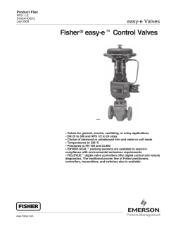
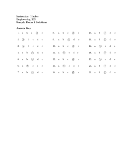
S erv c e
Snap
ij
i
Jd
s
NISSAN ENGINE
MODEL P
SERVICE MANUAL
I NISSAN I
NISSAN MOTOR CO
TOKYO
if
JAPAN
LTD
c
NISSAN ENGINE
MODEL
P
SERVICE MANUAL
INISSANI
1
NISSAN MOTOR CO
r
TOKYO
t
j
JAPAN
LTD
FOREWORD
This manusl has been complied for pourpose
of assisting NISSAN
distributors and dealers for effective service and maintenance of the
Model P engine
Model P engine has been used for the various models of vehicles
such as Model 680
Model 4W73 and Model 60 series
In addi
Each assembly of major components is described in detail
comprehensive instructions
pectioo of these assemblies
tion
are
given
for
assembling
and ins
680 4W73 and 60 are also given in this
engine concerned
It Is emphasiged that the ooly genuine Nissan Spare Parts should be
used as replacements
The difference between Model
manual
as
far as
CONTENTS
GENERAL INFORMATIONS
Page
SPECIFICATIONS
FERFORMANCE CURVES OF NISSAN MODEL P ENGINE
GENERAL INSPECTION OF ENGINE
SHORT CUT FOR TROUBLE SHOOTING
SECTION
1
CYLINDER
1
1
Cylinder
1
2
Cylinder
SECTION 2
2
1
2
2
2
3
2
4
2
5
15
PISTON RING
Piston ring and piston pin
28
Connecting
30
32
rod
CRANKSHAFT
CAMSHAFT
VALVE
1
Removal of
2
Removal of valves
cylinder
4
3
Replacement
4
4
Valve
4
5
4
6
1
5
2
Inspection
5
3
Heat control
1
2
7
3
43
TIMING
head
MANIFOLD
5
7
7
TAPPET
39
grinding
Refitting the cylinder head
camshaft
Timing gear
SECTION 5
SECTION 7
37
of crankshaft
Rear bearing seal
4
1
23
23
4
2
CONNECTING ROD
Disassembling
SECTION 4
6
PISTON PIN
25
1
6
7
10
20
Piston
2
SECTION 6
4
15
head
PISTON
SECTION 3
3
3
CYLINDER HEAD
1
Removal
47
51
52
52
52
53
54
57
57
57
assembly
57
WBRICATION SYSTEM
59
Adjusonent of oil regulstor
60
Oil filter
63
COOLING SYSTEM
fan belt
Water pump fan
Repair of water pump
heat indicator
Radiator thermostat
67
67
68
72
Page
SECTION 8
8
1
8
2
FUEL SYSTEM
Fuel pump
Repair of fuel pump
77
78
80
8
3
Carburetor
8
4
Adjusanent
8
5
8
6
Air cleaner
Gasoline strainer
8
7
Gasoline tank
SECTION 9
9
1
9
2
gasoline
84
87
87
gauge
89
93
Check
repair
Adjusanent
101
10 2
95
100
GENERATING SYSTEM
103
Generator
103
104
Cautions for handling generator
Carbon pile type voltage regulator
10
3
10
10
4
5
10
6
105
106
Troubles and remedy of generator and regulator
Test of generator
Wiring of generator voltage regulator
SECTION II
1
STARTER MarOR
Repair
SECTION 12
12
of carburetor
IGNITION SYSTEM
SECTION 10
1I
77
1
1I0
adjusanent
III
lIS
lIS
BATTERY
Handling
and out put
of
battery
119
119
GENERAL
INFORMATIONS
SPECIFI CA TIONS
ENGINE PROPER
Model
Maker
Kind of
P Engine for 680 60
4W73 Series
Nissan Motor Co
Ltd
Gasoline Engine
Engine
Water
6
Cooling
Cylinder Arrangement
Cycles
Straight
4
Combustiem Chamber
Head
Bore x Stroke rom
Total Displacement Volume
Bath tube type
Over head valve
85 7 x 114 3
Cylinder
Compressiem
Compressiem
3 956
I
7 6
157
145 3800
cc
Ratio
Pressure IbiD
200 rpm
Maximum Horse Power HP Irpm S A E
235 ft Ills 2000 rpm
Maximum Torque m kg rpm
Minimum Fuel Conswnptiem at Full Load
h rpm
Dimensions
rom
Engine
g
32 5 2000
220 1600
904
P S
Width
Rear
Height
Length
right to Air
Support
Air Cleaner
to
Cleaner
Fly wheel
left
655
882
293
Oil Pan
Engine Weight Equipped
Number of Piston
Fan to
Rings
dry kg
Compression
2
I
Oil
Type
Steel strut
LO EX
of Pistem
Material of Piston
Valve Timing
140
SOO
open degrees B T D C
closed degrees A B D C
Inlet Valve
Inlet Valve
Exhaust Valve
Exhaust V lve
520
open degrees B B D C
closed degrees A T D C
120
Valve Tappet Clearance
0 38
0 38
mm
Inlet Valve hot
mm
Exhaust Valve hot
Ignitiem Method
Ignitiem Timing
Firing Order
Starting
Battery
B T D C
0 4
0 4
IgnitiCll coil
100 450
Irpm
5 3 6 2 4
Crank Handle
1
Startor Motor
Method
IGNITION SYSTEM
Ignition Coil
Distributor
Model
Model
HITACHI CIZ OI
D6Q8 5IA 60 series
Vacuum Control
Centrifugal
HITACHI D608 01
Type of Spark Advancer
I
Sparking plug
Model
854E or B6E
Maker
Diameter mm
Sparking Clearance
Number of pole
Insulating
N G
K
HITACHI
or
14
O 75
mm
I
Material
Porcelain
FUEL SYSTEM
Carburetor
Original
Model
VC42
Type
IA 680 Series
Maker
Dia
Dia
of lbrottle Valve mm
of Ventury Tube mm
Dia
of
Dia
Dia
of Low
Stromberg
VC42 4A SA 60 E690
FG60 4W73
HITACHI
42
36 17 IO
1 43 VC42 IA
High Speed Jet mm
lo
of Econanizer Jet
Draft Direction
Air Cleaner
4A
VC42
35
Speed Jet mm
SA
0 55
loW
Downward
mm
Type
Oil Bath
Maker
Tsuchiya
Nwnber
Fuel Feed Pump
I
Type
Diaphragm
Maker
Showa Seiki K yosan Denki
LUBRICATING SYSTEM
Method
Pressure Feed
Gear Pump
Type of Oil Pump
Type
of Oil Filter
Oil Pan
Paper Filter
Capacity Itr
5 3
680 series
6 7
60
series
COOLING SYSTEM
Forced Circulation with
Method
Radiator
Centrifugal Pump
Type
Centrifugal Pump
Fin and Tube
Type of Water Pump
Thennostat
PeIlet
BATIERY
2SMC
Model
Voltage
Capacity
12 volt
amp
60
hr
20 hr
rating
E690
120Aj30h
I
Number
Tenninal
positive
grounded
2
side
GENERATOR
Model
Maker
HITACHI
Shunt wound
12 volt
Type of Winding
Voltage
Capacity kw
Type of Voltage Regulator
RIIS SO
200W
Carbon pile
GI4Q 07 F680 E690
STARTING MOTOR
Model
MFB
Maker
Volt
HRZ
HITACHI
Power
v
hp
12
8114 23
3
S114 21
I0
E690
PERFORMANCE CURVES OF NISSAN MODEL P ENGINE
Max
150 I
Max
Min
145 HP 3800 r p m
32 5 kg m 2000 r p m
220 gr jHP h l600 r p m
P
SAE
Torque SAE
Fuel Consumption
B H
I
V
140
130
J
F
120
17
E
no
J
S
35
100
I
C1
iii
30
Iii
5
u
c
c
I
aJ
I
80
1
c
o
I
70
Ii
cI
60
E
I
c
I
50
11
V
40
c
1
E
r
30
8
12
16
20
24
32
28
36
250
8
aJ0
0
I
38
u
c
en
Engine Revolutions
4
Xl00
r
pm
E
G1NE
LE
SIDE
r
5
tf
i
P
T
i
Jt
f
m
ir
c
z
j
t
1
7X
S
4
ENGINE RIGHT
6
SIDE
GENERAL
In order to maintain the
adjuBtment
1
INSPECTION
engine
at
OF
the beBt condition
a
ENGINE
periodical
orderly
Check of Cooling Water
The cooling sYBtem must be full of water which is required
clean
Refer to the line up of Cooling System
2
and
have to be made
to
be soft and
Check of Banery
The quantity of electrolyte is required to be as much aB 3 8 inch above the
The voltage
The specific gravity should be more than 1 220 kg
plates
at each cell Bhould be more than 17 5 volt on the excell tester
Refer to the line up of Electrical
3
Check of Engine Oil
The oil level should be between the upper and
The oil capacity is 6 2 Itr
The Btandard oil pressure is 3 5 4 kg cm
lower lines of the oil level gauge
at running speed
49 5
57 Ib in
Refer
4
to
Check of Spark Plug
The gap should be adjusted
Refer to Ignition SYBtem
5
System
the line up of Lubrication
to
O
6
O 7
Check of CompreBsioo Pressure of
mm
0 024
O 028 in
Cylinder
when
The compreBsioo presBure should be over 135 poundB per square inch
difference
of
The
pres
meaBured by rotating engine with Btarting motor
inch
This
sure at each cylinder should not exceed 10 pounds per square
water at
test should be made under the conditions temperature of cooling
800 all
700
plugs removed and the throttle and choke valves of
carburetor
6
point gap
at
0 020 inch
Ignition Timing
the
timing
at
20 before top dead
Check of Carburetor
Refer
9
the
Check of
Adjust
8
open
Check of Distributor
Adjust
7
spark
completely
to
Fuel
System
Check of Fuel Pump and Strainer
Refer
to
Fuel
System
7
center
crank
angle
10
Check of Tension of the
Fan Belt
i
ft f
When
pressed by a hinge the
deflection of fan belt should be
25 mm I in
at the middle of
pwnp pulley and crank
shaft pulley
water
II
Check of the Valve Tappet
Clearance
Adjust
the clearance at
0 38
0 40 mm 0 015 0 016 in
for both intalce and ex
haust valves when engine is suf
ficiently wanned
at
12
600C
Cheek of Slow
Refer
13
to
Check of
Fuel
for Carburetor
System
of
Tighteness
Cylinder
Head Bolts
Adjust them
14
to
be 55
65 ft lb
Check of Charging Rate of
Generator
It should read
more
than 10
amperes at the engine speed of
30 40 lcm Ihr Refer to
Fig
Electrical
15
Disgnosis
See Fig
of
Engine by
Means of Vacuum
2
8
Gsuge
1
N
IlUIl
Aramd 18
aum
wlth
to
1dIIopeed
8t1ellT
Drops
W
ftC
IIfaht ftuc
tuatiDD at
four
normal
2
t
wheD
enafDe
risions
di
CuRt
Ia
Maalfald
or
or
J
lea
of
11m1
steady
tween 8 to
Late Jpido
2
bKk to about
openiq
d
and
GaIde
Vibrates fast between
8
k Pia
Gap
too 8ma11
kn
Point Contact
11m1
be
Remam
15
steady
be
tween 14 to 17
CyU Hsd
c bL
FIoaregularly
tween 5
net 19
Fig
comes
zero
V
dhl
a
ea
Val
LalIT
hllDll
to
14 aDd 18
Late
Remains
3
drupe
23 wbea
2
c
1
V
regularly
8pr1q
LalIT
5
reodbIll
apwer
aldi
accelerating
mgIDe
and becomes areater
s Increasing speed
InclJcates
emIdDa
R
III
e
VaI
From 10 to 22 when
of
81 fa
Po CooodItIoa
c1adng throttle
1IIIIy
m
fn
reading
Vain
accelentilll
IkImt
Val
O
OU
1CoDdItIoa
a
tbe
to 2 aDd
IplUp bock to 25
Choked H
Normal at tint drops
to
zero
3l d
builds up to 1
be
Diagnosis of engine by
9
Improper
l between 1 and 16
F1oat
theD
Vacuum
Cuf fa Oat
afttor
of Adlaat
t
Floats lIIowly between
13 and 17
Gauge
SHORT cUT
FOR
TROUBLE
1
Damage
SHOOTING
of fuel
pipe
or
insufficient
soldering
Piping
system
2
Insufficient
tightening
union nut 00 the fuel
Leakage
high
flowing
too
damage
of
1
Worn needle valve and
chamber
2
Dust at needle valve and seat in the
float chamber or inccxnplete move
1be fuel level
dfuel
or
pipe
or over
seat
in float
ment of needle valve
3
Fuel infiltrated in the float
4
1be float is too heavy due
weight of solder
5
Too much pressure of fuel pump
too big needle valve seat hole
I
Improper fastening of needle valve
to
the
or
Carburetor
seat ass y
2
Improper fastening of
cover
Improper fast
ening of jet
screws or
aged
screws on
the
of the float chamber
3
Loose emulsiCII
4
Improper fastening
5
Improper fastening of low speed jet
6
Improper fastening
tube
outer
dam
washer
1
Repair
Clogging
Loose
3
Crack
of low speed jet
size used
or
the jet
fastening
of low
speed jet
on the joint surface of the
and
lower bodies of carburetor
upper
or
fastening
Improper assembling of the throttle
valve
10
low speed
improper
2
4
of cracks
Poor adjustment for
of
rburetor
injector
of the upper and
lower bodies of carburetor or pre
sence
Adjustment
of pump
l5
6
Poor
Intrusion of air due to
valve shaft
Air
throttle
worn
frem carburetor
leaking
and intake manifold
flange
flange
idling
l Difference of compression of each
cylinder
Engine and
etc
of
spark plug
2
Irregularity
3
Poor quality of spark plugs
of different kinds
4
hnproper ignition timing
5
Intrusioo of air from the intake mani
fold or the rubber tube joint of the
window shield wiper is leaky
I
No fuel
2
Intrusioo of air from the throttle
valve shaft and its flange fixing the
aupply
to
gaps
or use
the carburetor
same
Car buretor
Hard to start or
3
too much
Use of poor quality fuel
mixture of substitute fuel such as
alcohol kerosene etc
4
Erroneous
1
Imperfect insulation
wiring
2
Poor ignition current due to the
under charging of battery
3
Disorder
unable to start
in cold climate
4
use
of
of choke button
ignition
of
high
tension
circuit
accwnula
Troubles of spark plugs
tion of carbon
damage by heat ir
of
regularity of gaps ccmdenaaticm
and
water
oil
quality
lubricating
poor
etc
Engine and
other parts
Insufficient compression of
6
Air intrusion into the intake manifolds
7
Insufficient seating of engine valves
or
11
cylinder
5
broken or weak valve
springs
8
l
Insufficient
9
Poor
1
No fuel
2
Engine
quality lubricating
supply
oil
to the carburetor
for
low
adjust
speed
Erroneoua
4
Insufficient
lower body
1
Trouble of engine valves
valve springs
2
Poor ignitioo or insufficient cranking
apeed of starting motor due to drop
of battery voltage
3
Disorder of ignition circuit
4
Trouble of startor motor
1
Dirty
2
Excessive resistance for suction due
to
Carburetor
starting
3
Hard to start or
unable to stan
In hot climate
of
Too lean mixture due to poor
ment
Carburetor
cranking speed
motor
use
of choke button
tightening of upper and
or damage of gasket
or
broken
intake manifold
partial clogging
of air cleaner
3
Insufficient fuel supply due
lock In fuel pump and pipe
4
Disorder of fuel pump
5
Clogged
main
jet
to
power jet
vapour
or
main
air bleed
6
and adjustment of
ignorance of relative
of venturi tube main jet main
Wrong assembling
carburetor
Insufficient
and power
sizes
speed
air bleed etc
Engine
12
1
Too much friction and resistance of
bearings and other parts
2
Insufficient compression of cylinder
3
Overheating
4
Poor
5
Wrong setting of
6
Disorder of ignition system
7
Misfire of any spark
8
Brakes
of
engine
cooling system
dragging
octane
selector
plug
due to poor
adjustment
Carburetor
Wrong assembling
ance
jet
Overheating of
engine
Engine
and
of carburetor
ignor
of relative sizes of venturi tube
1
Too much friction and resistance
2
Poor
3
Inefficiency of cooling
4
Poor circulation of lubricating oil
5
Wrong ignition timing
6
Wrong setting of
7
Over
others
1
main
main air bleed
The
cooling
system
effect of radiator
octane selector
loading
porcelain part
of
spark plug gets
stained black with the carbon
Judgement
2
The color of exhasst gas is black and
has the unpleasant odour
3
Uneven
1
Wrong assembling
Air mixture is
too
rich
running of engine
carburetor
and adjustment of
ignorance of relative
sizes of venturi tube
air bleed
Cause
main jet
main
etc
2
The jet hole is
3
Insufficient fastening of main jet
4
Leakage
5
The level of fuel is
6
Disorder of air cleaner
1
too
big
in the power
jet valve
too
The porcelain part of
high
spark plug
is
white
Judgement
Air mixture is
too lean
Cau8e
13
2
Uneven running of engine
3
Back firing in carburetor
4
Engine overheat particularly
exhaust pipe overheats
5
Engine power diminishes
1
Poor adjustment of carburetor
2
Instrusion of air frem the throttle
valve shaft and the fitting flange
the
l
Back fire
3
Jets tampered
or
remodelled
or
imitation parts used
1
Too lean mixture
2
Wrong Ignition timing Pre ignition
3
Catch fire due
4
Disorder of
ignition system
5
Insufficient
seating of engine
springs
or
to
engine overheat
valves
broken valve
1
Disorder 6f
2
Clogging
of
accelerating
pump
accelerating
pump injector
hole
Insufficient
3
Leakage
frem
accelerating
pump check
ball valve
acceleration
4
Disorder of distributor governor
5
Wrong ignition timing
6
Poor adjustment of carburetor
1
Erroneous
2
Improper
adjustment
fuel
relating
of carburetor
to
compression
ratio
Knocking
3
Dirty cylinder inside
4
Wrong ignition timing
5
14
isorder of spark
plug
Pre ignition
SECTION
1
CYLINDER
Br
CYLINDER
HEAD
1 1 CYLINDER
Fig
1
DATA
Diameter of
cylinder
85 69 85 739 mm
3 3754 in
3 376 in
bore
fhe limit
for over size
piston
is
0 06 in
Thickness of
cylinder
13 64 in
sleeve
if over size more that
Use
The outer diameter of
O 060 in
sleeve should be less than 3 5695 in
wali
5
Difference of top and bottom
bore
Difference between the
and shorter diameter
of
an
Main
Block
oval bore of
0 00 1 in
Less than O 025 mm
longer
Less than O 025 mm
inside
limit of
use
0 001
in
0 08 in
dia
73
73 025
Not
to
mm
2
874
2 875 in
head surface
warpage
Tightening
mm
cylinder
bearing housing
cylinder
15
exceed O 1
torque of main
10
bearing cap bolts
15
11
kgrn 72
mm
0 004
80 ft lb
in
The engine is a six cylinder valve in head type equipped with counter balanced
crank shaft
The displacement of this engine is 3956 cc it develops 145 horsepower
at 3800 revolutions per minute SAE
Maximum torque is 32 5kgm at 2000 rpm
shows a view of the engine assembly in side cross
The illustration Fig 2
section
904
oC
N
or
Fig
2
Sectional View
of the Engine
it beccmes necessary to overhaul an engine assembly it
disassembled and all parts throughly cleaned before starting
Repair operations when
should be
completely
the overhaul operations
In order to
simplifty
the
following instructions we well cover the repair
job would be performed
of the
various parts in the order in which an overhaul
Checking Cylinders
the coodition of a
By far the best method to be used indetermining
dial gauge
engine preparatory to reconditioning is the use of a
Fig
3
16
cylinder
in an
such as is shown
Fig
3
Checking Cylinder Walls with Dial Gauge
The dial gauge hand will
instantly
and automatically indicate the
variation in the cylinder bores
In use
the dial gauge is simply inserted in the
and down its full length
It is then turned spirally
be desired
cylinder
taking readings
at
each
point
walls from top
In this
cylinder
or
bore
slightest
and moved up
completely rated
manner
at as
may
all variations in the
to bottom
may be determined
gauge corresponding with the exact diameter of a standard cylinder
bore is used to set the dial gauge
it is easy to determine the oversize piston to use
as well as the amount of metal which must be removed from the
cylinder walls to
make them true
If
a master
17
Cllliruler Borillll
When it becomes necessary to rebore the cylinders of an engine to install
pistons the instructions furnished by the manufacturer of the equipment
oversize
used should be carefully followed
ht this engines the piston clearance is allowed on the piston and this
taken into consideration when setting the cutter in the boring bar
1be piston to be fitted should be checked with a micrometer
below the lower ring groove and at right angles to the piston pin
should be bored to the same diameter as the piston
If micrometer is not available to measure the piston
bored 0 002 less than the oversize piston to be fitted
For
example
bored O 018
Cylinder
when
fitting
a0
020
oversize
piston
the
must
be
measuring just
The cylinder
cylinder should
be
the cylinder should be
oversize
Hone
cylinder has been r ebored within 0 002 of the size desired it should
polished with a cylinder hone
ht operation the hone is placed into the cylinder bore and expanded until it can
1be hale is then operilted up and down in the bore until
just be turned by hand
it begins to run free
During this operation kerosene should be used as a cutting
After
a
be refinished or
fluid
to keep the stones of hale clean
This procedure should be followed until the
piston being fitted can be pushed through the cylinder on a O 0025 feeler gauge
1be feeler gauge must be inserted vertically 900 around pistm from the piston
pin and draw out the feeler gauge with the scale under I 3 kg powers
18
3
t
F g
4
19
1 2
HEAD
CYLINDER
5
Fig
DATA
head
Cyl
height
all
length
Comhustion chamber volume
Length
of
Cyl
Power up En
06 mm
86
72 i O
5
Former En
100 I mm
99 80
cc
119mm
head
121
cc
mm
Within 0 004
O lmm
Warpage of surface
Tightening torque
Cyl head holt
Rocker bracket holt
55 65 ft lb
31 36 it lb
l 6 9 0 Kgm
4 3 5 0
Kgm
One of the most important units of any overhead valve engine is the cylinder head
but the valves
It contains not only the combustion chambers and spark plugs
inlet ports exhaust ports and the necessary water passages to maintain the proper
temperature of these important parts
No maintenance operation is more important than valve grinding from the stand
point of engine economy and performance
be used whenever valve are ground to maintain
Extreme care should
therefore
and
as
limits
cllellrances
only
by maintaining these limits and clearances can
factry
good engine
economy and
Checking
Valve Guide
performance
be obtained
to worn valve
Lack of power and noisy valves In many instances can be traced
is very important
valve
stem
the
vlave
and
the
clearance
between
The
guides
guides
and the exhaust be
The intake guides should be checked with a new Intake valve
beCause
the
dismeters
of
the
stems are different
checked wltl1 a new exhaust valve
20
t
r
Fig
21
6
SERvreE
NEWS
REFERENCE
NO
DATE
CONTENTS
OF SERVICE
JOURNAL
AND
BULLETIN
22
2
SECTION
PISTON PISTON RING
CONNECTING ROD
2 1
PISTON PIN
PISTON
The pistons
above the
are
made of LO EX aluminum
alloy
with three
ring groove located
piston pin
The skirt is eliiptic
These pistons are furnished in standard size as well as O 010
O 020
O 030
O 040
0 050
O 060
Any time a
piston removed from the cylinder It should be examined for carbon
ls
and any carboo deposit removed
on the inside
This helps keep the engine oil
clean
The piston pin is fixed 1 5 mm off set towards the thrust direction at the
center
of
piston
The pistons
are
serviced with the
piston pin fitted
in them
Should it become
necessary to Ins tali oversize piston pins
The proper fit of the piston pin is a thumb push fit
at 20oC
The plstoo pins are serviced in standsrd size as well as 0 0025
0 005
size
Note
Over size pistons for service use are as foliows
Piston is usually supplied as Set pistoo with pin
For
Size
STD
Connecting
rod 12100 58000 Piston pin bolt
Set piston
w
12010 58022
12010 58023
0 25
12010 58024
0 50
0 75
12010 58025
12010 58026
1 00
12010 58027
1 25
1
50
Piston
pin
0 12
clamp
type
Pin pistoo
12011 58002
12024 95960
12012 58002
12013 58002
12015 58002
12024 95960
12024 95960
12024 95960
12016 58002
12024 95960
12010 58028
12017 58003
12018 58003
12010 58029
120 I 9 58003
12024 95960
12024 95960
12024 95960
Part Name
Set piston
No
12010 58022
For
piston
12011 58002
combined oil ring
bolt locking type
con rod
Pin piston
12024 95960
w
pin std
Remark
23
use
with
over
Part Name
Set conrod
Part No
Remark
12130 58002
12100 58000
lOOsh
w
Ass y conrod
Rod connecting
12104 58000
Washer spring
Bolt hex
9 15116
I 34632
Cap
12106 58000
ccmrod
Bolt ccmrod
Nut hex
12109 58000
9 11246
Palnut
Bush ccmrod std
Pin piston std
12112 58000
12lll 58001
Pin piston O S
Pin piston O S
0 06 mm
O 12 mm
Pin piston O S
0 25
mm
12024 95960
12028 95960
12025 95960
12026 95960
Fig
Service spare parts
1
J
I
I
II
II
r
I
I
N
I
f
8R
74 68
Fig
74 42
2
Fig
24
0
0
3
mm
i
l
2 2
Interchangeability
New
coo
rod
can
be used with former type
piston pin
Former
con
rod
can
not be used with tbe new
piston pin
Applied
model
All P engine
Applied
from
E
E
E
P 32473 for 680 series Except Fire
P 32423 for 60 series
PF 2686 for all P type fire engine
Engine
NEW CON ROD
20 618
20 630
Fig
Part Name
Set piston
4
New No
Remark
12010 58100
For
Piston
12011 58100
combined 011 ring ill
press fit type
Pin pistoo
12024 58000
w
pin std
mm
con
use
with
roo
e
e
r
J
0
I
1
74
68
roC
iil
mm
74 42
Fig
5
25
Applied
model
All P engine
Applied
from
E
P 31592
Part No
Part Name
Set
12130 58003
Ibush
con w
Ass y
con
12100 58001
rod
1210458001
Rod connecting
Washer
Ncne
spring
Bolt hex
None
Cap
con
rod
12106 58000
Bolt
con
rod
12109 58000
9 11246
Nut hex
12112 58000
Palnut
Bush
For
con
std
rod
12111 58001
12024 58000
Pin
piston std
Pin
piston O S
0 06 mm
12028 58000
Pin
pistro O S
O 12
mm
12025 58000
Pin
piston O S
O 25
mm
12026 58000
Connecting
rod 12100 58001
Pistcn pin tight press fit type
Set piston
Size
w
Piston
Pin piston
pin
STO
12010 58100
12011 58002
12024 58000
o 12
1201058101
12012 58002
12024 58000
0 25
12010 58102
12013 58002
12024 58000
0 50
12010 58103
1201558002
12024 58000
O 15
12010 58104
12016 58002
12024 58000
1 00
12010 58105
12011 58003
12024 58000
I25
12010 58106
120 18 58003
12024 58000
1 50
12010 58101
12019 58003
12024 58000
PISTON
Piston pins
are
tightly
fitted in the ccnnecting rods
shown in the
It is advisable to use a special assembling tool NT 4245
oil on the outer
the
coat
To
ease
engine
6
fitting
light
following figure
surface of pin and inside of con rod pin hole before press in
be
When assembling with the special tool the end of the piston pin must
3mm 1 8 in
out of the piston boss face so that the connecting
approximately
rod is position
in the center of
piston pin
26
Pressure
1 5 3 5 ton
Piston Pin
Guide
Cat Rod
Pin
Insert
Bushing
hold piston
mly 00 the boss face
must
Stopper
Return spring
Base
Special TooI P Engine
Pisten pin Fitting NT 4245
6
Fig
Inorder
to
Into the con rod
modified
and
also the 011 ring
pin
slightly
deepen for the newly adopted combined oil ring
avoid distortion of
the inner ribs snd the base of
groove depth is
slightly
piston during press fitting pin
boss is
T7
3 PISTON
2
RING
AND
PISTON
PIN
All
compression rings are marked with the word Top cast in the upper side of
When installing compression rings make sure the side marked
ring
Top is
toward the top of the piston
Piston rings are furnished in standard size as well as 0 005
0 010
0 020
the
O 030
To
O 040
O 050
properly
fit new
O 060
piston rings proceed as follows
Slip the ring into the cylinder pressing it down about 2 inches
with a piston
This will square the ring in the cylinder
Check the gap between the ends of the ring with a feeler gauge
This should be from 0 006
0 010
Top
2nd 8 oil
0 006
to
to
to
0 015
0 015
O 012
0 25
0 38 mm
0 IS
0 30
into the bore
mm
If the space between the ends of ring is less than 0 005
remove the ring and
with a fine file dress the ends lfitil proper clearance is obtained
Fit each ring
separately
Carefully
the
piston
hang
remove
and
all particles of carbon from tbe faces of the ring grooves in
the grooves for burrs or nicks that might cause the rings to
inspect
up
DATA
PISTON
Type
Flat head invar steel strut
Aluminum alloy Lo Ex
445
460 gr
15 692
16 226
Material
Weight
oz
Diameter of piston skirt
Standard
85 650 85 699
mm
Over size O 12
mm
85 775 85 824
mm
Over size O 25
Over size O SO
mm
85 900 85 949
86 150 86 199
mm
Over size 0 75
Over size I00
Over size I25
mm
mm
3 4015 3 4034 in
mm
mm
mm
86 400 86 499
86 6SO 86 699
86 900 86 949
mm
3 4113 3 4132 in
3 4212 3 4231 in
Over size ISO
mm
87
mm
3 4310 3 4329 in
mm
Difference of major and minor
diameter
Width of ring groove
1SO 87
0 30 0 34
199
mm
mm
3 3719 3 3739 in
3 3769 3 3788 in
3 3818 3 3837 in
3 3916 3 3935
0 012 0 0135 in
Compression
2 530 2 555 mm
Oil
4 765 4 790 mm
0 0996 0 1005 in
0 1876 0 1885
in
Depth of ring groove
Compression
4 045
4
120
mm
0
1592 0 1692 in
Oil
4 045
4
120
mm
0
1592 0 1692 in
53 25 53 35
mm
0 031 0 049
mm
Distance from
the top of
piston
pin hoie
Clearance between cylinder wall
and piston measured at skirt
to center
of
28
0 0012 0 0019
in
in
Checking
of feeler gauge
Diameter of piston pin hole
Off set of piston pin hole
Weight
Weight
difference of pistDn only
difference of pistDn and
connecting
PISTON
rod
assembly
I5 3 5 kg at 0 0025 in feeler gauge
20 650 20 663 mm 0 8130 0 8135 in
I5 mm 0 059 in
NDt tD exceed 15 gr
Not tD exceed 5 gr
0 5
0
DZ
5 DZ
RING
Compression ring
Compression ring
No
I
Inner bevel type
No
2
Taper type
Oil control ring
Oversize rings available
Compression ring groove width
Oil control ring groove width
Compression ring width
Oil control ring width
chrome
plated
Slotted scraper chrome plated
O 12 0 25 O SO 0 75 I00 1 25
1 50 mm
0 005 0 010 0 020 0 030 0 040
0 050 0 060 in
2 477 2 490 mm 0 0974 0 0980 in
4 72 4
74 mm
3 8 3 6
3 3 3 5
mm
mm
0 1858 0 1866 in
0 1496 0 1417 in
0 1299 0 1377 in
Tension
Compression
No
CDmpressiDn No
I
I45 1 7 5lcg 3 1967 3 8581 lb
1 6 1 9 kg 3 5274 4 1888 lb
I2 1 6 kg 2 6455 3 5274 lb
2
Oil control
Ring Gap
CompressiDn
CDmpression
ND
I
0 25 0 40 mm
No
2
O
Oil control
Ring
0 0098 0 0157
in
15 0 30 mm
O 15 0 30 mm
0 0039 0 0118 in
0 0059 0 0118 in
0 04 0 05 mm
0 0016 0 0020 in
0 001 0 003 in
groove clearance
Compression
I
2
Oil control
PISTON
0 025 0 070
mm
PIN
Diameter
Standard
Oversize available 0 062
Oversize available 0 125
Length
20 653 20 648
mm
mm
20 722 20 710
mm
mm
20 785 20 773
74 8 74 4 mm
mm
74 68 74 42
Fit
2
mm
0 8131
0 8158 0 8153 in
0 8183 0 8178 in
2 9291 in
2 929 in
9402
680F
9448
2
Thumb fit at 200C
Press fit 1 5
3 5 metric
29
0 8126 in
ton
Slip
to
the outside of the ring into the groove and roll it entirely around the
groove
ring is free and does not bind in the groove at any point
Proper clearance of the piston ring in it groove is very important and when fit
make sure that the
ting
new
rings
the
clearance should be adhered to
0 015 should be very free but 0 003
At the second or oil control
groove
feeler should produce a light drag
following
At the top ring a O 002
feeler 0 001
feeler should cause the ring to lock in the
groove
the O 002
of proper size is not available select one which fits
slightly tight
emery No I placed upon the flat plate Rub the lower side evenly
sure the ring will not warp
the
If a
ring
ring
on
LOCATION OF
RING
grind
making
GAP
The leakage of compression pressure is often caused from the improper location
of ring gap in relocation to each other
When assembling the rings
locate the gap of
first compression ring toward Front Direction the second ring at 1800
toward
Rear Direction of the
angle
engine
and the oil
ring
at same
directioo of first compression
ring
4
2
The engines from the number P 31592 are assembled with combined ring
This
ring compose of two side rails and a special spacer is designed to control the
This flexible type which follows closely the sur
quantity of oil up and blOW by gas
face of the cylinder walls even when they are slightly out of round will perform
better sealling
new
Side rail gap
0 2 0 8mm
P Engine
Side rail tension
RIKVENT
3 5
kg
Maker
RIKVENT
NIFLEX
NIFLEX
Fig
7
30
Set Piston Ring
Second Oil
Make
Size
Remark
fop
STO
Niflex
12033 58004
From P 31592
STO
Rikvent
12033 58005
From P 31592
Spare parts
Spare
parts
Over Size
0 12
N iflex
12034 58002
0
12
Rikvent
0
25
Niflex
12034 58003
12035 58002
12035 58003
12036 58002
0 25
Rikvent
0 50
Niflex
0 50
Rikvent
0 75
Niflex
0 75
Rikvent
1 00
1 00
Niflex
1 25
1 25
N iflex
1 50
1 50
Niflex
12039 58003
12040 58002
Rilevent
12040 58003
lnstructions for
Spare parts only
12036 58003
12037 58002
12037 58003
12038 58002
12038 58003
1203958002
Rikvent
Rikvent
lnstalling Combined Type Oil Ring
for
Following instructions and illustrations are mainly for Rikvent but as
rail
for
Rikvent
the
of
it
is
the
same
as
gap
Niflex oil rings
except
positioo
just
angle
450
Installing Spacer
lnstall spacer in bottom groove with spacer
For easy installation hold
gap over piston hoss
one end of spacer in the groove and fit it gradually
Make sure spacer ends
around into the groove
shown
as
below
are butted properly
Top
Rail
Use either of the two steel rails
no right
or
wrong side
of spacer with thumb
end of rail on top side of spacer ends
rail across ends and on around into the
Holding ends
Place
Coil
one
groove
Botton Rail
lnstall remaining steel rail
spacer with gap
approximately
on
lower side of
20 30 mm right of spacer ends
31
FiTUJI
I1Ulpection
Check final
assembly
to
make certain
Rails are not off spacer
Gaps of rails and spacer are nor lined
straight
Spacer assembly can be turned manually
with
ease
Spacer gap
Installing
is
directly
over
Pisto1Ul into
Use steel band tool for
piston boss
Cylinders
installing pistons
into
cylinders
For NifleJ Oil
Ring
Install two rails
from spacer gap
so
that each gaps are 450
Fig
Lower Rail
8
Upper Rail
Gap
Spacer Gap
NlFLEX
Fig
5
2
CONNECTING
9
ROD
DATA
F SOO
Material
Steel
Length center to cetner
Big end housing width
200 199 9 mm 1 874 7 870 in
31 55 31 50 mm I2422 I2402 in
Big
end
housing
diameter
Type
Overall length
Outside diameter
forging
60 180 60 199
mm
2 3693
2 3700 in
Thinwall steel backed white metal
25 9 26 1 mm 1 0196 I0275 in
60 199 mm 2 3700 in
32
Thickness
Standard
Undersize available
0 25 mm 0 OlD in
1 SOOmm
0 593
0 0590 in
1 633
1 625 mm
0 0643
O SO mm
0 020 in
1 758
1 750
mm
0 0692
0 75
0 030 in
0 040 in
1 883
1 875
2 000
mm
0 0741
2 008
mm
0 0790
0 0738 in
O 0787 in
O OlD
0 064 mm
0 0004
O 0025 in
mm
1 00 mm
Big end bearing
Connecting
clearance
Tightening
time a
removed from
an
connecting rod
is
O 0640 in
0 0689 in
rod side
clearance
Every
1 508
O
torque of cap bolt
IS
0 28
5 5 kg
m
mm
0 0059
O OllO in
40 ft lb
connecting rod is
engine or a new
being installed it
should be checked for
alignment
on a
connecting rod alignment fixture as
shown in figure
Place the piston pin in the eye of
the rod and
tighten the clamp screw
connecting rod on the
aligner arbor and tighten the con
Place the
necting rod bolts
bent or twist
bar
If there is any
correct
it With a bend
install the piston and
check the alignment as the illustration
The maximum allowable limit of bend
ing
Next
is 0 004
The bearing metal should have a
good contacting surface over an area
more than 70
of it
Such a bearing
too
much clearances between the
pin and big end of the connecting
carnk
rod will be found scored over the sur
faces of the metal
And in extrem
the metal surfaces will even
cases
tually
be cracked
much own
replace
If the metal is
with new
so
bearings
Check connecting rod end clearance
between the upper half of the
rod and the side of the crank
Fig
10
connecting
pin with
feeler gauge
Lock the
The
bolt
pal
connecting
nuts
rod bolts
nuts
by installing
new
pal
nuts
must be installed with the open side of the nut coward the end of the
As a final and last checkto be sure that the
assembly will travel true with the
check the clearance between the crank pin and connecting rod side
This should not be less than 0 004
0 10 mm
bore
33
tl
0
rEgE
J
f
1
GAlJ GE
0 15
028
t
1
1
Fig
11
ti
t
f
c
i
12
Fig
Inserting Piston
Insert
was
taken
each
piston
Connecting Rod
and
connecting
it is essential that the
F
rod
assembly
into the
cylinder
mark on the boss of the
piston
from which in
is
positioned
towards the engine front
side
The oil hole of big end of connecting red must be positioned and toward the
of manifold
the
Compress the piston rings with inserting piston using tool and gently tap
is clear of the piston
bar
the
the
wooden
until
the
with
end
of
the
piston
top of
piston
unit
clamp
34
Now push the piston down the cylinder block IDUil the big end of the connecting
rod just protrudes through the bottom of the cylinder bore then position
upper half
bearing shells
3S
SERVICE
NEWS
REFERENCE
NO
DATE
CONTENTS
OF SERVICE
JOURNAL
AND
BULLETIN
36
SECTION
3
CRANKSHAFT
Fig
1
DATA
CRANKSHAFT
Material
Special
Construction
With
Diameter of main
No
steel
forged
forging
weight
counter
journals
68 229
I
68 204
mm
2 6862
2
6852
in
No
2
69 300
69 275
mm
2 7283
2 7273
in
Out of round limit
Crankpin diameter
Out of round limit
Runout of crankshaft
Not to exceed 0 0125 mm 0 0005 in
57 ISO 57 131 mm 2 2500 2 2492 in
Not
to
exceed 0 0125
Not to exceed 0 075 mm
center
Main
journal
clearance
Crankshaft end play float
Shims available for above
Pilot bearing hole diameter
0 0005
0
in
003 in
bearing
0 03 0 096 mm 0 0012
O 125 O ISO mm 0 005
0 0037 in
O 006 in
O 13 0 76 mm 0 003 0 005
O 030 in
23 774 23 800 mm 0 9359 O 9370
0 07
in
Pilot bearing length
Number of teeth crankshaft gea
mm
31 8
27
37
mm
1 252 in
at
MAIN
BEARING
Type
Thinwall steel backed white and clevite
metal F500
Number of
7
bearings
Length
No
1
No
2
No
4
41
mm
1 6142 in
Clevite
No
7
49
mm
1 9291 in
Clevite
3
5
33 8 mm 1 3307 in
White
26 mm 1 0236 in
Clevite
6
Outside diameter
ltiside diameter
No
73 025
1
68 283
mm
2
8749 in
68 299
mm
2 6883
2 6889
69 371
mm
2 7304
2 7311
in
No
2
No
7
69 355
in
Thickness white metal
Undersize available
O I
O
O 2
12
0 004 O 008 in
0 75 1 00 1 25
mm
0 25
1 50 mm
0 005 O OW 0 020
O 050 O 060 in
Tightening
cap bolt
torque of
0 030
bearing
10
38
11
kg
m
J2
80 ft lb
0 040
3 1
DISASSEMBLING
OF
CRANKSHAFT
I
Fig
39
2
When the crankshaft is
being removed check it carefully in the following order
remedy any defect according to the requirements called for
Measure the journal and crank
pin with a micrometer and if they are oval
shaped or tapered more than 0 002 or of the surface of journal or crank pin is dam
aged correct those defects
Support the No 1st and No 7th journals with V block
and
Fig
Apply
3
dial gauge
to sixth
fifth fourth third and second journals
if there is the deviaticn of more than 0 002 inch
The belt shaft should he corrected with a press
a
the shaft to
the
Support
flange
and rota
see
and rotate the crankshaft same as the said
way apply a dial guage to
the part to connect the flywheel
If the surface of flange is wabbling
than 0 001
0 025 mm have it fixed up
When the journal or crank pin is worn flat
more
or
beyond the limit
rough
0 004
or over
or
oval
replace
or
if
they
are
scored
cut
it with a new one
Clear
out throughly the oil passage
by blowing out wIth a compressed air
Main bearing is manufactured to be easily removed with the crankshaft in place
A void repeated use of old hearings
Check throughly before it is installed
Such
bearing as excessively worn out or making poor contact or having
rough or hardened surfaces are to he replaced Carefully inspect the
thrust part of the No I bearing and if there is any wear take up the wear by
scores
side
a
cuts
removing the shims
If the
wear
these shims
is
and washer
beyond
placed between
the thrust washer and crankshaft
side thrust clearance of O 004 0 007 replace
2 1000 in
6 1000 in
the
regular
13 1000 in
When replace these shims
tap up the crank gear with a adapter and measure
the clearance between the bearing back plate and the thrust washer and correct the
clearance of it
40
Fig
4
41
Fig
42
5
2 REAR
3
BEARING
SEAL
This resr main bearing is sealed by a wick type seal installed in a groove
To install a new wick seal at the rear main bearing
machined in the block and cap
insert the
cap
packing
in the groove with the
FIg
Then using
When
a
rolling
rounded tool
the
packing
fingers
6
roll the packing into the groove
start at one end and roll the
packing
to
the
center
of
the groove
The above
Then starting from the other end again roll toward the center
bottom
into
the
of
the groove
procedure insures that the wick is finnly pressed
each end
at
wick
which
from
the
small
of
the
groove
The
protrudes
portion
cut flush with the surface of the bearing cap
To prevent the possibility of pulling the wick out of the groove while cutting off
the ends
it is recommended that a round block of wood the same diameter as the
be used to hold the packing firmly in position while the ends are
crankshaft
should be
glange
being cut
off
of the wick seal it will
If it should become necessary to replace the upper half
be necessary to remove the engine from the chassis and remove the crank shaft
is exactly the same
The procedure for installing the wick in the cylinder block
as
for installing it in the bearing cap
1
Wash and clean the crankshaft and bearings
2
Apply marking compound lightly
3
Install upper and lower bearings in their
crankshaft in the cylinder
4
Rotate the crankshaft hack and forth
the contacting condition of bearings
over
43
each
journal
own
of crankshaft
position and install
the
Remove the crankshaft and check
5
The upper half bearings have
its
contacting
make contact
to
evenly
and more than 70
If any insufficient contact is found
area
replace
it with
of
a
new
me
6
The lower half
the area
bearings
also should be
making
contact
Sometimes
evenly over 70
bearings
excessive clearance of the lower half
makes it impossible to show the
contacting condition
journal
case
replace
with the lll1dersized
of
to
the
In such a
can be made
Make shift repair
bearing
by filling off the cap and bearing to take up
bearing fit after the above work Repeat the
satisfactory fit is obtained
in case of absolute necessity
the clearance
Re check the
work until you are sure
7
After
appl y
8
checking the cmtacting
engine oil plentifully
cmdition
wipe
off
marking compound
Install the seventh bearing and cap and tighten with
tighteness by rotating the crankshaft
a
and
regular force
Check
the
10
Fig
9
Proceed
to
11
7
the next
ft lb
80
72
k
Tightening
bearing
Torque of Main Bearing Cap Bolt
in the same manner
and have all the
bearings
adjusted
10
If bearing fit is properly adjusted
rotated by grasping No 2 and No
pins
II
with a
slight starting
After above work is
rench with the scale
on
all
journals
5 crank pins
the crankshaft can be
or
No
3 and No
4 crank
but without any resistance after started
completed
be sure to lock the cap bolts with torque
44
SERV
E
NEWS
REFERENCE
NO
DATE
CONTENTS
OF SERVICE
JOURNAL
AND
BULLETIN
45
SERVICE
NEWS
REFERENCE
NO
DATE
CONTENTS
OF SERVICE
JOURNAL
AND
BULLETIN
46
4
SECTION
CAMSH
FT
TAPPET
VALVE
TIMING
Adjusting
Bracket bolt
Set
Lock
Rocker shaft bracket A
Rocker shaft bracket B
k
Rocker shaft cliP
screw
WaSher
screw
nut
I
2
O
Outside spring
f
e
o
i
0
Bush
1
0
o
Valve
fl
L ExpansIOn plug
I
58000
ii
13209
Valve
Pu
retainer
Valve cotter
spnng
Valve
IS
Valve rocker
Right side
Valve rocker
Left side
h
r
ad
Intake
Ex
Exhaust
V81vedr ilO
Thrust washer
Timing gear
9
r
27319
70 1518
@
J
70 1519
Carn
A
shaft bearmg
Figo
1
13006 58000
13005 58000
Camshaft
Fig
2
47
Valve
A
t
8
I
Oil pwnp
drive gear
Lifter
5
5800J
Fig
2
B
DATA
CAMSHAFT
Special
Material
Journal
steel
forging
diameter
No
1
49 149
49 124
mm
1 9349
1 9339in
No
2
48 945
48 920Iilm
1 9270
1 9260 in
No
3
48 641
48 616
mm
I 9150
1 9140 in
No
4
48 336
48 311mm
1 9030
Cam
41 246
height
Fuel pump
cam
offset
3 00
1
9020 in
1 6238 in
mm
3 IOmm 0 1181
O 1220in
Runout of camshaft
Not to exceed O 025mm 0 001 in
Drive
Helical gear
Cam gear number of teeth
54
Bearing clearance
O
Ql
O 10
mm
0 0004
0 004 in
Bacldash of camshaft gear and
crank gear
O 1
48
O IS
mm
limit of
use
O 25
mm
CAMSHAFT
BEARINGS
Frcnt
steel backed white metal
Thinwall
Type
bearing
Out dia
before fitting
Inside dia
52 555
52 530
49 303
49 238
mm
2 0690
2 0680 in
1 9410
1 9384 in
reamed in
position
29 24
mm
1
29 49
Housing diameter
52 476
52 541
mm
2 0659
2 0684 in
62 375
52 3SO
mm
2 0619
2 0609in
position
49 123
49 058
mm
1 9339
1 9313 in
Length
19 0
Housing diameter
52 273
52 248
mm
52 070
52 045
mm
2 0500
48 818
48 753
mm
1 9220
1 9194 in
mm
1610
1 1511 in
Length
Second bearing
Outside dia
Ins ide ma
before fitting
reamed in
in
0 748
mm
2 0579
2
0569 In
Third bearing
Outside dia
Inside dia
before fitting
2
0489in
reamed in
position
19
Housing diameter
51 740
51 943
mm
2 0370
2 04SO in
51 740
51 715
mm
2 0370
2 0360 in
48 488
48 423
mm
1 9090
1 9064 in
Rear
mm
0 748
in
Length
bearing
Outside dia
before
fitting
Inside ma
position
reamed in
Length
31 8
Housing diameter
51 664
Undersize available
mm
1 2519in
51 638
0 25
mm
O SO
mm
mm
0 0098
in
0 0197 in
VALVES
Timing
Inlet opens
Inlet closes
Exhaust opens
Exhaust closes
Head diameter inlet valve
Head diameter exhaust valve
140B T D C
SOo A B D C
520 B B D C
120 A T D C
43
mm
36 2
49
1 692 In
1 425 in
mm
2 034
2 033 in
Seat
angle
45
Inlet and exhaust
Seat width
inlet and exhaust
14
0 055 in
1 8 mm
Limit of
O 071 in
3 32 in
use
Stern diameter
Inlet
8 650
8 637
mm
0 3405
0 3400in
Exhaust
8
8 627 mm
0 3401
0 3396in
Length inlet
Lift
and exhaust
640
131 5
9 6
overall
mm
5
1772 in
0 378 in
mm
0 016 in
O 40mm 0 015
Water tamp 80 C
0 38
Working clearance
GUIDES
VALVE
Length
72
exhaust
Inlet
Outside diameter
Inside diameter
8 685
Hole for valve
guide
diameter
2
mm
15 048
8346 in
15 030 mm
8 700 mm
15 018
15 000
0 5923
0 3419
mm
0 3916 in
O 3425 in
0 5905
0 5912 in
Valve stern clearance inlet
0 035
0 063
mm
0 0013
0 0024 in
Valve stem clearance exhaust
0 045
0 073
mm
0 0017
0 0028 in
VALVE
SPRINGS
Free
length
Fitted
length
and load
2 2638 in
57 5
mm
49 5
mm at
23 5 kg
1 9488 in
at
52 lb
3 4
Number of working coils
5
Diameter of coil wire
4 5
Core diameter
turns
mm
33 5
0 1771
33 Omm
in
1 3189
1 2992 in
TAPPETS
Type
Diameter
Hollow barrel
23 990
23 W5
mm
in
Length
55
50
mm
2
1653 in
0 9445
O 9438
ROCKER
MECHANISM
Push rods
Length
388
Stem diameter
7 15
mm
mm
0 2815
in
Rocker shaft
Length
641 mm 25 24 in
20 000 19 971 mm
Outside diameter
0 7874
0 7862
in
Rocker
arm
bushing
Type
Rolled
phosphorus
Outside diameter
23 45
23 43
InBi de diameter
mm
bronze bushing
0 9232 in O 9244 In
reamed in
position
20 020
Inside diameter before
reamed
19 98
20 033
19 93
mm
mm
0 7882
0 7865
0 7887 in
O 7846 in
Clearance between shaft and
bush
Rocker
O 02
O 054
mm
0 0008
O 0021 in
arm
Bore
22 40
Lever ratio
1 47
22 37
mm
0 8818
0 8807 in
I
Tightening
B
4 1
K T
torque of rocker
boit
REMOVAL
Drain the
cooling
OF
water
4 3
CYLINDER
5 0 kgm
HEAD
by opening the radiator and cylinder block side
taps
Disconnect the radiator hose
Remove the air cleaner carburetor
manifolds
drain
rocker cover and the inlet and exhaust
Detach
high tension cables and remove the spark
Remove the rocker cover and the corle washer
Detach the manifold assembly
plugs
assembly for getting to sladen the cylinder head bolts
Withdraw the push rods
Keeping them in the order of removal
The cylinder head can now be lifted from the cylinder blocle
Talee off the rocleer
same
time
To facilitate
detaching
the
cylinder
head joint
head
51
tap each side of the
cylinder
at
III1IIIIIIII
Fig
4
REMOVAL
OF
3
VALVES
After the cylinder head is removed the valves can be take
To do this
compress the valve spring with the valve
out
spring compressor
Remove the
cotters
of valve retainer
Release the valve spring
valves from the guide
3
4
retainer and oil seal from stem
Withdraw the
REPLACEMENT
The diameter of exhaust valve head
place
are
the valves insert each valve into its
retainer and compress the valve spring
Refit the valve cotters and
Remove the compressor
4 VALVE
secure
smaller than the inlet valve
To re
and
the
oil
seals
replace
guide
spring
them by
releasing
the compressor
GRINDING
Before replacement of the cylinder head the valves and their seats should be
examined for signs of pitting or burnt platches and distortion
If these conditions are present the valve seats must be recut before
attempting
to
grinding the valves wilst distorted valve head should be corrected or the valve
renewed
Only
the minimum amount of metal should be removed in the
52
trueing process
When
grinding
a
valve
on to
its
the valve face should be
smeared lightly with grinding paste
sealing
and then lapped in with
grinding tool
The valve
seat
must
with a semi
be
a
suction type
ground
to
motion
rotary
light coil spring interposed
its
A
between
the valve head and the port will assist
considerably when lifting the valve in
order
to rotate
the face to a different
position
This should be done
the
spread
frequently to
grinding compound evenly
It is necessary to continue the
grinding
process until
surface is
produced
an even matt
on
the
seating
and
the valve face
On completioo the valve seats
and ports should be throughly cleaned
with gasoline soaked rag and dried
and the
subjected
to a
compressed
air
blast
The valves should be washed in
gasoline and all traces of grinding
compound removed
Fig
5
4
REFITTING
THE
CYLINDER
Fig
53
5
HEAD
4
Ensure that the cylinder head and
cylinder block
are clean
The cylinder head gasket is
joint faces
marked upper face
head in correctly
TOP
so
that it will be placed
Place the gasket into positioo and fit the cylinder
head
securing bolts finger tight
They screw into
cylinder block at the front and rear bolts holes on
the manifold side and guide the head into
positicm
Insert the push rods replacing them in the posi
tions from which they were taken
Screw back all
the tappet
adjusting
screws
Replace the rocker assembly and screw down the
securing nuts finger tight
Evenly tighten the cylin
der head bolts
diagcmally
finally pulling
them down
from the center to out side
a
torque wrench
set
55
65
ft lb
Reset the valve clearances and finally check
engine not so hot or cold The cylin
der head bolts may pull down slightly more after the
them when the
attained its normal
engine has
working temperature
in which case the valve clearance will have to be
checked again and
at
reset
if necessary 0 38 0 40
un
60oC
6
4
Fig
TIMING
GEAR
a
6
CAMSHAFT
If there is an excessive amount
of end
play
in the camshaft
it is
necessary to remove the gear and
camshaft assembly and correct the
falts
When the camshaft and gear are
assembled to the engine it is im
portant that the punch marks on both
the camshaft and crankshaft gear
must be fitted as
7
The cam
Fig
shaft will then be in its proper posi
tion so that the valves will open and
close in the proper relation to the
movement
of the position
After the camshaft and crank
shaft gears are in their proper
places check the crankshaft timing
gear for run out with a dial indica
tor
This should not exceed O 15mm
Then check backlash of the camshaft
This should not exceed
gear
O 25 mm
Fig
54
7
SERVICE
NEWS
REFERENCE
NO
DATE
CONTENTS
OF SERVICE
JOURNAL
AND
BULLETIN
55
SERV
E
NEWS
REFERENCE
NO
DATE
CONTENTS
OF SERVICE
JOURNAL
AND
BULLETIN
56
SECTION 5
MANIFOLD
5 1
REMOVAL
Remove intake and exhaust manifolds
assembly
from
cylinder head
These manifolds are held together at the center bos by the stud bolts
After removal wash and clean both intake and exhaust manifolds
16174 58000
11
194
oft
2
2
2
11638 1
15116
9
J
1
1
Q
14628
14518
14020 58000
70 1956
14006 58000
9
A
11
16110
31628
9 11140 1
1
Fig
2 INSPECTION
5
flanges must be all em the same plane Inspect manifolds
by placing
flanges on a flat surface
If it is found warped resurface on surface cutting equipment
Manifold
for warpage
their
Also check for cracks and lr eakages
5
HEAT
CONTROL
and replace if defective
ASSEMBLY
deflects a parts of the hot exhaust gas to and around the intake
Heat control has a thermostatic
valve and facilitates fuel evaporation
the
action
above
spring controling
automatically
If this spring is worn replace it
Gaskets between intake and
When installing manifolds place new gaskets
manifolds
head
and manifold assembly
exhaust
and
between cylinder
This
assembly
manifold by
a
gasket
57
SERV
E
NEWS
REFERENCE
NO
DATE
CONTENTS
OF SERVICE
JOURNAL
AND
BULLETIN
58
SECTION
6
LUBRICATION
SYSTEM
Fig
1
Oil Pump Assembly
Relief valve
Oil pump body
Shaft
Drive gear
Drive shaft pin
Bottom
pump cover
1 11412
9 15114
Fig
2
Components of Oil Pump
59
As
in
the engine oil forced out by the oil pump Is ramified
circulating through crank shaft main bearings cem
bearings lappet valve rocker arm and other lubricating
by connecting rod splshes the postons and cylinder walls
The oil regulator is instrument to adjust the
pressure of oil so as to keep il
at specified
This adjustment can be done by either increasing or de
pressure
showing
Fig
3
into two series and the one
necting rods camshaft
creasing
6 1
the number of pressure
ADJUSTMENT
OF
adjusting
OIL
washers
REGULA TOR
Remove the
the connecter of
The oil
oil pump
fixing bolts of the pump body at
regulstor is attached directly to the
Oil pressure should he kept 3 5
4 0
kg
driving spindle
em
JJ
t
t
Fig
3
Lubrication
of Engine
Fig
Insert
4
Disconnect Oil Pump from
the Block
regulator valve into the oil pump body and measure the clearance A
hetween end of valve and Slop
pin This clearance between the end of
valve where spring cOlltact should be 18 mm
Fig
5
60
18mm
Pump body
Regulalor
Oil
Fig
5
Setting the Stop
61
Pin
valve
RELIEF
Free
VALVE
Length of
Spring
Length
Valve
41 5
After
SPRING
when
fitted
30 3
mm
mm
Thickness of Adjusting
Washer
Compressive
Load
Immand2mm
0 040 O 080 in
2 24 kg
the above points calculate thickness of the
the equatioo below and assemble it
Thickness of adjusting washer
A t 18 mm
30 3 mm
inspecting
following
adjusting
washer
DATA
OIL
PUMP
Type
Spur
Gear
8
39 40 39 35 mm 1 5511 1 5492 in
29 960 29 935 mm 1 1795 1 1785in
of gear
Number of teeth
Gear diameter
length
Knock pin diameter
3 18
3 23 mm 0 1251
O 1271 In
Oil pump shaft
Diameter
12 TI6
Length
190 2
189 8
0 025
0 1175 mm
O 008 in
0 001
Gear back lash
If
12 958
mm
0 5108
7 4882
mm
0 003 In
Gear vertical clearance
0 040
O 115
mm
0 0016
Gear in
O ISO
O 260
mm
0 006
body
clearance
regulator
Built in pump
Oil
regulator
Min
0 5
kg
7 4724 In
Replace
over
Oil
0 51011n
O 0045 In
O 010 in
body
cm
7 lb
in
at
running
speed
Measurement of oil pressure
regulator
Pressure of
regulator spring
Clearance between pistem and
and body
2 24
kg
O 002
30 3
mm
high
O 0025 in
If
over
0 005 in
Replace
Pressure
Running
3 5
Idling
0 5
4 0
kg
kg
cm
em
SO
7 lb sq
57 lb sq in
in
at
oil temp
70 SOoC
Sump capacity
Oil
5 3 litres 1 4 gal U S A
S A E
MS No 20
For temperature
No
62
30
above 300C MS
Check the clearance between the drive gear and bump body
The clearance
should be O ISO
O 260 mm
If this clearance or others which showed in the series data should too much over
replace the gear with a new part depending em whichever may be the cause of the
excessive clearance
FILTER
OIL
6 2
The oil filter is mounted on the
left side ci the engine
As for the oil filter which
serves to filter of engine oil within
the oil pan Is of the full flow type
using the paper elements
This elements should be taken
out for
periodical check and
cleaning
For
disassembling
unscrew
the
shaft at the
cap bolt of the center
of
filter
after
draining oil
top
body
from drain plug
The filter element should be
changed at each 4 000 miles or at
shorter intervals if the oil get dirty
socmer
In assembling be sure the
tightening
new
bolts
packing
considered
The
tightl y
and
to
gasket
place and
in
are
used if
leak the oil
capacity
of
be checked every
engine oil should
day
The oil capacity is measured by
vided at the
pr
side of cylinder
The oil level
the oil level gauge
right
kept between the upper and
lower lines of the gauge
Change
engine oil every I SOO iniles in its
of oil
degree of viscosity Select a good quality
must be
63
Fig
6
Relief valve
Out let hole
In let hol
Drain
PIug
ft1
Fig
7
Sectional view of oil filter
tightening
torque
Center bolt 2
Relief valve
0 6
64
7 5
kg
cm
2 5
kg m
opening pressure
SERV
E
NEWS
REFERE
CE
NO
DATE
CONTENTS
OF SERVICE
JOURNAL
AND
BULLETIN
65
SERV
E
NEWS
REFERENCE
NO
DATE
CONTENTS
OF SERVICE
JOURNAL
AND
BULLETIN
66
SECTION
COOLING
7
SYSTEM
2
I
3
Radiator
2
Fan
3
Thermostat
4
Water pump
S
Cylinder
6
Cylinder block
head
Fig
7 1
WATER
PUMP
FAN
a
FAN
I
1
2
3
4
5
6
7
8
9
10
11
12
13
14
15
16
17
18
Water pump body
Cover
Vane and shaft BSS Y
15
1
BELT
14
11
16
2
Pulley
Seal retainer spring
Seal retainer
Rubber seal
B8 kelite
seal
Vane soap ring
Water pump shaft bearing 5
Bearing spacer
Front seal plate
Rear seal plate
Felt cover plate
Felt seal
Shim
snap ring
Lubricator fitting
Beailng
9
Fig
2
10
4
Sectional View of Water Pump
67
17
DATA
Water pump type
Centrifugal
Pulley
1 28
ratio
to
1
Fan blade
Number
4
Diameter
476
Thickness
1 6mm
mm
18 7 In
Fan belt
Type
Lengtb
Angle of V 40 degrees
1175
1181 mm
46 250
46 500 in
V
outer
Deflection
tensioo
25
adjustment
Fig
2
7
REPAIR OF
WATER
mm
1 in
3
PUMP
of troubles in the water pump such as water leakage worn or burnt ball
remove the unit to repair
It is better to remove the
bearings
radiator before the water pump is displaced
In
case
of the pump shaft
1
Disa88emblll
of Water
Pump
1
Remove fan blade from the
2
Move the generator toward the engine after
generator and take off the fan belt
3
Remove the
4
water
pump
pulley removing the eight
loosening bolts holding
by pass rubber hose at water outlet spacer
Remove three bolts which hold the water pump body to the
68
cylinder
screws
the
block
5
Draw
out
washer
6
cotter
Pull
pin
in the castle nut on the
pump shaft and remove nut and
out pump
pulley from
the shaft
using a puller
and
remove
woodruff key
Remove four bolts
fastening water pump cover to its body and displace the
and gasket
Take OUt vane from bearings in pump body assembly
As a rule this ope
ratiem is to he done with the use of
press
When the hammer is used in
stead never fail to use a copper hammer and tap the end of shaft
lightly
If other wise you are likely to bend the shaft or
damage the screw threads
Now the vane assembly will Come off from
pump body together With five
accessorieB such as seal retainer spring seal retainer rubber seal bake lite
seal and vane anap ring
Remove the vane snap ring first and the seal retainer
seal retainer
cover
7
8
9
spring
rubber seal and bakelite seal are removed from the vane
assembly
In case shaft bearing or felt seals is in bad shape remove shaft
bearing
snap ring and take out the front seal plate washer shim shaft
bearing spacer
pump
2
rear
seal plate
bearing
felt
Ner
C
plate and felt seal from
Auemblg
of Water
Pump
In order to assemble tIle parts after
having finished
invert the order of disassembling work mentiooed above
care is to be taken in
handling
1
washer
body
necessary repair works
However the follOWing
Put the vane assembly with the shaft pointing upward
Grease the shaft
lightly and insert the seal retainer spring so that the smaller diameter
comes to the bottOm of the shaft
Fig
69
4
2
1Sj VI
ttfi
See that the rubber seal fits on
the shafl with proper tighteness
J
T
i
il
F
t
t
if
I
t
9
The proper tighteness is deter
by the rubber seal sliding
mined
em
the shaft when
with
3
After
having assembled
assembly with
i
pushed lightly
fingers
retainer
seal
seal system
water
seal retainer
e
t
tg
the vane
spring
rubber seal
seal
r
bakelite
check
snap ring
whether the unit is In proper
The unit is in
working order
good shape If the bakelite seal
vane
ff
snaps back to its proper place
when depressed with a thumb and
freed
If the seal does not return
instantly
and without
drag
it i
t
due to weakness of the seal re
tainer
spring
or too
i
of the rubber seal Remove such
a seal and inspect the bore of the
C
i
seal and if found blamable for
fitting rebore Until it
properly On the cemtrary
stiff
cause
new
0 A
Wi
fits
if the
is found in weak seal re
tainer
4
spring replace
spring
t
it with a
g
7
Fig
assembly
to
set it to the shaft
stall the shaft
the pump
Yc
j
r
r
1
5
Cover the felt seal with sufficient grease and
cover plate and rear seal plate
Then in
shim washer front seal plate and snap spring
body
spacer
l
t
together with felt
bearing
i
fo
Jii
F
In order to assemble shaft
first insert the
bearing etc
vane
ff
tight fitting
4
to F Jt
Jiil
t
1 f1
2 f
Fig
6
70
l
4
r
1 r
t
5
In fastening the cover 10 the pump body with four SCrews proceed as
for two screws in the
follows
upper middle use spring washers for the
one positioned lower left
facing toward the pump use a copper washer and
for the fourth SCrew in the lower right
use a shake proof washer
All of
them have to be screwed up
is thaI it prevents water
6
tightly The reason for using the copper washer
leaking through the screw hole
After installing the cover on pump body put the woodruff key em the shaft
and fix water pump pulley
Examine turning the pulley if the vane assembly
7
In
runs
the pump always use new gaskets for cover and body
Better
result would be obtained if the new gaskets are coated with shallac or white
lead before they are replaced for keeping water tight effect
Water
3
smoothly
assembling
Pump
Ordinary
Troubles and Remedies
troubles in the
waler
pump are water
leakage
vibration
noises
Causes of waler
I
Rubber seal in bad
b
Bakelite seal in bad shape
Retainer spring fatigued
shape
d
Friction surfaces of pump body and bakelile seal
e
Body
g
Wrong
h
Worn
Anyone
have
be
to
leakage
2
vane
gasket
shaft bearings
or
bent shaft
of the above will cause water
replaced and loose
have to be
wabbling and
a
Worn
b
Bent vane assembly shaft
Loose pump body screws
or
leakage and damaged or worn out parts
tightened up in order to SlOP the
surface of the pump body can be reground
screws
The wear of the friction
Causes of vibration
c
noises
burnt ball bearing
Of the above burnt ball bearing is caused from poor
Replace it with a new one and feed grease sufficiently
ting
in the pump
supply of oil
through lubricator
fit
body
Periodical supply of chassis grease to
kilometre run
4
worn
in poor shape
or loose screws of the
pump cover
or loose screws of the pump body
or cover
f Wrong
and
leakage
a
c
wabbling
A4justmellt
water
pump is
to
be made for each 1 000
of Fan Belt
The tensiem of fan belt is to be adjusted so that the belt has 1 2 3 4 inch
free movement as illustrated in Fig 7
To make the adjustment
Loosen No 1 bolt first and next No 2
Move the
generator and push the belt with a hand so that there is a free movement of 25 mtl
on
adjusted too loose it would make the
fan
and generator as well as premature
of
the
slip resulting
performancl
of the belt and the overheating of engine in summer
If it is held too tight
the bolt
belt
Fasten the bolts
wear
bearing
If the belt is
in
to
would be
damaged
71
Fig
7
RADIATOR
7
Adjustment of Fan Belt
THERMOSTAT a
HEAT INDICATOR
DATA
RADIA TOR
Water tube
Type
Pressurized
Cooling
water
capacity
pressure type
0 4 0 5 kg cm2 5 7 7 lb sq in
Model 680
4W73
60
16 ltr
16 ltr
17 5 ltr
4 227 U S Gal
4 6 U S GaI
THERMOSTAT
Type
Temperature to start open
Temperature full open
REPAIR OF
1
Cleaning
Pellet
71 50
86 50
74 50C
89 50C
1600
1870
l660F
1930P
RADIATOR
of
Cooling System
of the cleaning of radiator for a long while or use of improper or
for cooling purpose bring forth the overheating as formation
of rust and sedlment in radiator and water pump will result in poor water
circulalion
To clean the radiator proceed as follows
Neglect
impure
I
wster
Drain the
cooling
water
by opening
the drain cock at the bottom of tbe
radiator
2
Loosen the clamps of radiator inlet hose and the outlet hose
of radiator and disconnect them from the engine
72
at
the sides
3
Plug
up the Inlet hose opening that connects with cylinder water outlet
of proper diameter and securing it in place with the
using a wootl block
clamp
4
5
Remove the radialor filler cap and
pour in pure water letting it to run out
freely from the outlet hose
The cylinder Water jacket is cleaned in the same manner as for radiator
Clean water is poured in from the cyllnder water outlet ilnd drained
from
the radiator outlet hose
When the water tubes of radiator Core are
clog
ged and cause overheating remove the radiator from the chassis to clean
6
First remove radiator from the chassis
7
Plug
8
Heat the soldered
up the outlet port
of radiator tubes
that
they
are
Is empty
at
9
If other wlse
Scrape off completly
a
water
up to the top
of radiator core and upper tank With a burner so
Never heat the soldered
when the radiator
sean
seam
separated
radiator tubes and will
the bottom of radiator and fill
the heat will melt away the soldered parts of the
cause
leakage
the scales and other
impurities in the water tubes with
thin stick and flash the insides of water tube and lower tank with clean
waler
10
After
finishing
the above operation
assemble the
core
and upper tank by
soldering
Care
must be taken to make the connections stremg enough to withstand
vibrations of the vehicle in leakage by motioo and to prevent it from be
caning leaky
2
Pressure
Test of Radiator
After disassembling and cleaning of a radiator test it by water pressure of
than 5 pounds per square inch to locate any leaky spot
As even a little
leakage will cause overheating while running the leaks must be repaired by sold
more
ering
3
The
1
Water
Cooling
Cooling water
must be filled
always up
to
the overflow pipe at the top of
radiator
2
Hard water
cooling
or water
cootaining
alkali substance is to be avoided for
use
of
water
Such water liable to form scale or sedimenls and will cause poor circu
latioo of cooling water with the result of an overheating
3
After an inevitable use of improper waler fill up the system with solutiem
of two pounds washing soda and four gal1ems of warm water and make the
solution circulate the system by running the engine at low speed for twenty
or thirty minutes
Then open the drain cocks locsted at the right of en
of
the
cylinder block and the radiator to drain the whole solution To
gine
l ave no drops of the solutiem within the system clean the radiator with
flashing
Care
water three or four times
filling up the cooling system with soda solutiem or at
overflowing due to boiling of the solution in circulation so as
the liquid splash over the painted parts as otherwise the paint
must
be taken In
the time of
not to let
color would be affected
4
When the engine has been overheated and old water is introuduced in the
system cylinder block or cylinder head is liable to crack or warp
73
So
keep
late the
5
the
engine
is
stopped before feeding cold
water
and will have undesirable effect
the
cold
winter or whenever is liable to freeze
During
waler from the radiator and
engine
Be
sure to
rear
it will not circu
water
right
never
fail
open both drain cocks at the bottom of the radiator and
side of the engine to
completely drain the water
74
to
drain
at
the
SERvreE
NEWS
REFERENCE
NO
DATE
CONTENTS
OF SERVICE
JOURNAL
AND
BULLETIN
75
SERV
E
NEWS
REFERENCE
NO
DATE
CONTENTS
OF SERVICE
JOURNAL
AND
BULLETIN
76
SECTION
FUEL
8 1
8
SYSTEM
FUEL
2
PUMP
3
4
1
I
Upper body
2
Valve retainer
3
4
S
6
Cap
Diaphragm
Valve
Coonector
Rocker ann
Rocker arm spring
Rocker arm pin
Lever
Hand primer pin
7
8
7
q
to
11
12
13
14
Packing cap
Diaphragm spring
Lower body
14
9
15
16
8
Fig
1
Valve
Diaphragm
Fuel Pump
DATA
Type
Diaphragm spring
Free length
Fitted length I
tload
Mechanical
diaphragm
60 4
mm
22
arm
9 5
mm at
21
Rocker
61 6
pump
2 3779
2 4251 in
10 5 kg 0 8661 in at
23 lb
spring
Free length
29 5
30 5
7 05
7
1 1614 in
mm
1 2007 in
Valve spring
Free
length
Valve thickness
15
mm
l5mm
0 2776
0 2815 in
0 590 in
Performance
Max
output
2 8 litres min or over 0 74 gal USA
cam 1000 rpm suction height 600 mm
23 6 in
Max
outlet pressure
suction vacuum
220
Max
Hand primer output
400
250
mm
15 7 in
Approximate
10 strokes
77
hg
8
mm
hg
200
cc
66
9 84 in
or over
12 2
cu
in
hg
OF
2 REPAIR
8
FUEL
PUMP
Measurement of Rocker Arm
1
Before disassembling the fJlel pump measure lhe gap between the rocker arm
and the flange of lower body with a square and a scale as illustrated in Fig
snd check lhe wear of rocker arm rocker link and pin
be 1 9 64
When the play of the arm is taken up the above mentioned gap should
and
hecause
the
arm
link
rocker
pin
inch and if found less than this il is
The gap measurement is
excessively worn and therefore it needs remedy
ward the body until the resistance of diaphragm
delermined by pushing the arm
clearsnce
spring is felt as well as the rocker arm and the rocker link leave no
al the shaft of diaphragm
are
2
Fig
2
Construction
of Fuel Pump
and Measurement of
Rocker Arm Wear
of Ports
Inspection
air before
Wash and clean the parts wilh gasoline and blow tith compressed
attended
items
should
be
Undermentioned
specially
making the inspeclion
1
Whether
phragm
2
Whether
phragm
3
or
not
gasoline
is
infillrating
due to the wear or
there is any crack or wear in the
shaft and link
Whether
or not
or
not lhe
conlacting surfaces
are worn
78
at
rocker
damage of
connecting part
arm
cam
dia
of dia
and the link
4
5
6
Whether or not locker arm and diaphragm shaft are worn or cracked
Whether or not diaphragm spring arm spring and valve spring are fatigued
Whether or not there is wear or deformation in valve and seat
Troubles
COllses
and Repairs
Poor fuel supply
This will happen when gasoline leaks
1
due
to
crack
Replace a new diaphragm
diaphragm spring is fatigued or broken
The regular height of spring are one inch
placed
for outer spring
Any spring of less height has to
damage
or
fatigue
of
disphragm
2
In
3
of
case
In case the
5
be
be re
and two inch
replaced
check csp bolts for tighteness
In case fuel or air leaks
If this does
4
a new one must
for inner
through cap gasket
not stop the leakage
gasket is to be replaced
wash it with gasoline
screen is clogged with dusts
check if valve is bent and re
In csse there is leak in inlet or outlet valve
with a new one if necessary
Allowable limil of bend is 0 001 inch
place
When the conlact surfaces of valve
eat
and valve
are
found in poor condition
The
the oUllet valve seat and polish the face with a fine oil sleme
Therefore
to amend the sur
inlet valve seat is not removable from body
When the surface of valve is
face of valve seat
use a cutter and grinder
remove
not
smooth
polish
the valve
lightly
em a
glass plate
Slandard thickness of valve is 1 16 inch
6
coated with fine emery
If worn beyond the
compound
limit replace
Standard height of valve spring is 7 05 7 15 mm and if it is found extremely
fatigued replaced with new spring
In case there is an extreme amount of play at the contact surface of rocker
or when rocker arm pin hole is worn too much
replace
arm and camshaft
the arm with
a
new one
and remove the dia
To correct the above condition disassemble the body
of
between
lhe
lower
Inslall a packing
thick paper
body and dia
phragm
and raise the relative positiem of diaphragm shaft with the lower
phragm
body
7
In case the contact surface of rocker arm and rocker link is worn replace the
But for a makeshift repair emboss the link at the
and link altogether
means of
where it contacls the arm
welding and then finish
arm
by
part
the surface with file
phragm
8
9
a
exygen
simpler repair
can
be done
by using paper
dia
in 4
explained
In case the contact part of diaphragm shafl and rocker link is worn out re
place the diaphragm assembly
broken or bent replace free of
is fatigued
In case the rocker arm
spring
spring
4
as
Also
is 29 5
30 5
mm
Over Flow of Gasoline from Carburetor
I
2
it
In case spring pressure of diaphragm is tampered and made too strong
Don t monkey
will happen that gasoline overflows from the float chamber
with the pressure of locker arm spring
be sure to use the flange
In case fuel pump is installed on cylinder block
The failure of installing the gasket is sure to cause overflow
gasket
3
gasoline leaks
damaged or worn out
In case
the cause will either the
Replace
If the ventilation hole of the lower
leak into the engine oil pan
diaphragm
is cracked
it with a new one
body
resulting
79
is
clogged
in diluted
with dirts
engine
oil
gasoline will
5 Attention for
I
Assembling
the
Pump
Don t tamper the
3
spring pressure of valve diaphragm and locker arm by com
pressing or expanding
When setting the Inlet and outlel valves in the
upper body as well as valve seats
and gaskets
be sure the valves seat snugly in place
Always use a new cap gasket in the upper body
4
After
2
assembling
check the air
tight conditw and free actiw of valve If the
il is due to the poor fitting of valve
valve spring and
To obtain air tight valves
holder
they must seat snugly In the valve
and the springs should not be bent
valve action is not
spring
seats
In
5
good
the upper and lower bodies
line up screw holes of upper and
diaphragm Push rocker arm toward the body so that the dia
is at the bottom of its slroke
Then tighten the body screws
assembling
lower body and
phragm
it sure that the
help diaphragm
6
making
diaphragm
move
does
not
up and down
wrinkle
freely
alemg
its
and insure
edge
a long
This
life
care
will
Inspection
When the
is finished
assembling
the
following
items are to be checked before
installing
1
2
The distance from the rocker arm to the flange of lower body is
Set a vacuum gauge in the inlet port of lhe upper
Operate the rocker
y
arm with hand three or four times to its full stroke
The gauge should show
450mm hg vacuum and keep it for more than three seconds
To check the
pump without gauges choke the inlet and outlet ports with fingers and push
lhe rocker arm
After about three seconds
let go the finger from inlet
Also leI go the finger from outlet port after about five seconds
If a
strong suction sound is heard in the former and If a strong blow out sound
is heard in thlatter case you can assume lhe pump is in good
working shape
After the pump has been installed to the engine
port
Connect the
on the side of Inlet port
leaving intact the pipe em
Rotate the engine six or seven turns with the crank handle
and see If gasoline flows out from the outlet port
Connect the gasoline pipe to the outlet port and tighten up connections
Run
gasoline pipe
the outlet side
the
engine idling
and check ccmnectims if they
are
fuel and air tight
3 CARBURETOR
8
The carburetor used is the Hitachi Model VC 42 and is of lhe down draft type
It is equipped with a boOSl type power system and the main carburetting system
consisting of a triple venturi and an air ventilation pipe a low speed carburetting
system
The
pislon lype accelerating pump and a fuel economizer system
appropriately for each of the various conditions of starting
medium speed high speed and accelerating
a
burelor functions
idling
80
car
DATA
Hilachi VC42 IA for Model 680 VC42 4
for Model 4W73 and 60 series VC42 5A
Type
FR40
Downdraft
throttle and choke valve
linked
42 mm I6535 in
36 x 17 x 10 mm I417 in
Throat diameler
Venturi diameter
x
669 in
x
0 393 in
143 for Model 680
Model 4W73 and 60
Main jet
No
Main air bleed
jet
No
No
70
55
Slow air bleed
No
210
Power
No
Slow
Slow
jet
by pass
4
hole
Needle valve diameter
C dimension
Accelerating pump
bore
Imm
2 0
19
m
0 7480 in
0 ff787 in
Choke valve
Fuel level height
Poppet
20
stroke accel pump
Pressure em fuel
Functioning
valve
22 mm 0 7874 O 8661 in
4 3307 in
1I0mm hg
II
full choke
Output
in
mm
2 0 mm
Power valve start open
Degree throttle valve open
1
110
0 1575 in xO 0394
0 ff787 in
7 8mm 0 3070 in
x
Idler hole diameter
at
No 135 for
I8 cc 0 1098 cu in
0 3 kg cm2 4 26 lb sq in
of the Main Carburetting
System
from the fuel pump is
The fuel which has been sent under constanl pressure
needle valve and float
The
the
float
the
action
of
chamber
sent into the float
by
and is connected
vent pipe becomes the vent passage subject to negative pressure
In spite of the variations in the resistance
to the interior of the float chamber
the
fuel
level constant thereby maintaining lhe op
lhe
cleaner
acl
to
of
air
keep
timum mixture ration constant
the venturi
lhe air flow velo
As the intake air passes through the throat of
of
becomes high
and the air pressure near the opening
the
throat
city through
it
is
the
that
becomes lower than
atmospheric pressure
the injection nozzle
becomes
negative
Because of this suction
the fuel stored in the float chamber
Fig
81
3
is melered
Simulta
jet and drawn out through the injection nozzle
entering thorough the main air bleed mixes well with this fuel
which is lhen expelled as a fine spray from the tip of the injection nozzle
The float valve spring is located within the float needle valve assembly and
prevents lhe fuel level from rising excessively or overflowing because of the move
ments during operation
by
the main
the air
neously
Functioning
2
lion
Speed Carburetting System
This system operates for lhe slow speeds
the throttle valve is opened only
slightly
is low
Ccmsequently
for lhe slow
the main
speed operation
developed below
as
the Slow
o
carburetting
is created
lhe throttle valve
The
idling
During slow speed
opera
and the air flow rate
of course
system is inactive
principally by
functieming
The mixture
the
of
negative pressure
the slow speed system
is
follows
The fuel in the floal cham
by passed al the main jet
Power valve
Piston
ber is
10
the slow
jet by
which it is
metered
and mixes with the air
which has entered through the
slow
The fuel
speed sir bleed
regulated suitably by lhe
slow speed adjusting screw and
is injecled
The by pass port consists
is then
of a
lengthwise slot and a Imm
hole snd delivers lhe mixture
for slow speed when the open
ing of the throttle valve is ex
tremely
small
However
as
the throttle valve
the
opens
gradually
mixture is ejected
from the hole
snd the transi
tion from
speed
slow
to
inter
mediate speed is made smooth
ly without irregularities such
as pauses in the
ction
Throule valve shaft
Fig
3
Functioning
o
the
Accelerating Pump
4
and Economizer
The acceleraling device of this carburetor is of the
piston type synchrcnized
with the lhrottle valve shaft
It is equipped with lhe pump piston and pump injector
which temporarily supply a rich mixture and the power valve and
power jet which
supply a very rich mixture when sudden acceleration or high power is required
The device functions as follows
If while the vehicle is
driven at a conslant speed
the accelerator
being
pedal
is
pressed down for acceleratiem the pump pislon descends in accordance
with the descent of lhe
connecting plate and injects the fuel below into the venturi
from the tip of pump injector
This fuel had previously been drawn from the
float chamber through lhe check valve and stored below lhe piston
This action
82
provides
the necessary acceleration
Pump injector
If the accelerator is depressed further
the throttle valve will open further
Then
which its
opening becomes 110 mm Hg
from the fully closed position
the end of
power valve roo moves down
together
with
descent of the connecter to push down the
valve
Simultaneously a new fuel passage
is formed between the float chamber and
main
and the fuel of the float chamber
through the fuel port is metered by
jet
enlers
the power jet goes oul of the end of lhe main
jet and is ejected from the injection nozzie
together with fuel of
the main
carburetting
system
As a result and
is
extremely righ
mixture
supplied
Air check bowl
Because the various parts such as the
venluri jels
and air bleeds of this carbu
retor
have been
designed
and constructed
provide optimum fuel air mixtures
practically no adjustment other lhan that
for slow speed and fuel level is necessary
80 as to
Fig
5
Choke valve
Fig
6
The parts mentioned above have been assembled in accordance wilh the re
sults of rigid tests
Therefore arbitrarily varying lhem must be avoided How
ever
as a general rule
making a jet larger will make the mixlure richer and
making
it smaller will make the mixture leaner
If an air bleed is made large
if it is made smaller the mixture will become
the mixture will become ieaner
richer
83
4 ADJUSTMENT
8
OF
CARBURETOR
The slow
speed adjusting is made by means of the throttle valve adjusting screw
The throttle valve adjusting screw regulates
speed adjusting screw
the rOlational speed for slow speed
Screwing it in causes lhe speed to increase
and unscrewing it causes the speed to decrease
The slow speed adjusting screw
adjusts the fuel air mixture ratio
it
in
cause the mixture to become
Screwing
leaner unscrewing it causes the mixture to become richer
The slow speed adjusonent must be made with correct coordination between the
settings of these two adjusting screws The procedure is as follows
and lhe siow
h
7
I
y
t
l
I
t
i f
C
I
Fig
I
First set the
by
2
7
engine speed approximately
al
slow
speed
of 350 10 400 rpm
of the throttle valve
means
Next
c
adjust
the slow
adjusting screw
speed adjusting screw so that
the
engine
rotates
smoolhly
3
Needle
Then adjusl the rOlating speed pre
cisely with the throttle valve
adjusting
screw
If lhe slow
speed adjusting
screw
in with too much force
its tip will
be damaged and become the causes
of
improper operation
screwing
be careful in
even
when this
screw
in a certain amount
is still 100 rich
that the slow
not
clogged
high
not 100
therefore
it in
If
is screwed
Float
the mixture
check
to see
speed air bleed is
that the fuel level is
and that lhe
seating
of the floal needle valve is
good
84
Fig
8
valve
Adjusting
the Fuel Level
be high
If the fuel level in the float chamber is too high the fuel consumption will
too
the
if
lhe
fuel
level
is
low
and over flOWing will be caused
On the other hand
lhe
correct level
be
maintained
at
In
lean
therefore
it
must
mixture will be too
general
when the
engine adjustments are
adjusted correctly
to
be made
Otherwise
chamber must first be
the fuel level in lhe float
correcl
adjustment
cannot
be
made
Without special equipment the correctness of the fuel level cannol be determined
Ordinarily the following method will produce lhe correct level
directly
2
First remove the fuel pipe from the float chamber cover
Remove the three float chamber cover screws and take off the cover
Turn carburetor cover upside down so lhat the float is on lop and the float
3
needle valve is held in its closed position by the weight of the float
then gently lower it untillhe flap like contact
Lift the float with a finger
touches
the upper end of the needle valve and hold the
the
float
of
plate
just
I
4
valve spring
float in this position without pressing down on lhe needle
Ll
belween
lhe lower
lhe
distance
in
this
check
With the float
position
the chamber cover
surface of the end of the floal and the upper surface of
the adjustment is correct
If this distance is from 20 to 22 mm
Fig
5
If
holding pin
plate as shown
extract the float
not
angle
9
of the
contact
making this adjustment
be broken off from
headed
because
the float
lhe float
and adjust the
Be careful in
photograph
bending is forced the arm may
remove
in the
if the
Also because the needle valve is
be careful not to let it
drop
85
out
togelher
with its
not
spring
Fig
6
10
Check the seating of the needle valve
replace the needle valve assembly
to
the valve
If
seat
leakage
exists
the power jet starts to function when the throttle
mm
This adjustment is determined by the
opening
If the position of this
posilion of the adjusting nul of the power valve rod
the functioning of the power jet will be delayed and
not is on the low side
As described
previously
valve
becomes
110
high side
adjustment
the
if it is on the
functioning
will be hastened
press down lightly with a finger on the power
in
as
shown
the
valve rod
accompanying illustration until the resis
Move lhe throttle
tance of the power valve is felt then hold this position
The
lever until its matching mark coince des with that on boss part
Then raise or lower the
throttle valve opening will then be 110 rom HG
nut so thaI connecting plate jus I touches the upper surface of the
For correct
adjusting
adjusling
nut
1 e
the
point
at
which the power valve
begins
10
function
Adjustment of Connecting Rod
Insert the connecting rod inlO choke
lever post
Keeping downward the arroW
the
marked on
choke lever post sel its tip
to lhe side groove of the connecting rod and
As for its poSilion
fix it up with setscrew
it is so arranged lhal when the choke valve
is
totally closed
the
opening degree
throttle valve will stand
at
Connecting rod
Setscrew
of
Rod
11
Side groove
Fig
86
11
post
5
8
AIR
Cleaning of
CLEANER
Air Cleaner
The air cleaner serves to clean the air
before it is suctioned into the cylinder
1
If the cleaner has been in
service
for
considerable length of lime withoul
having been cleaned the accumulated
a
dusts within the cleaner interferes
free
This will
of the air
passage
a
re
sult in poor engine performance and
As any
increased fuel consumption
for Model 4W73 and 60
dust
particle
mature wear
in the air will cause pre
of cylinder wall air
cleaner should not be
dispensed with
kept clean aU the time
by periodical inspection and cleaning
and it should be
unscrew the
To clean the apparatus
nut on top of the cap and remove
wing
the
Take out the steel wires and
2
b
for Model 680
cap
gasoline Filllhe bowl
oil
up to the specified level
engine
ReinstaU the wires after having been
dried and soaked with oil
clean them in
Fig
3
12 Air CleaneT
with
If
The cleaning of the apparatus should be made every 3 000 miles
fre
districts
more
in
dusty
however the vehicle is used customarily
quent cleaning is advisable
6
8
STRAINER
GASOLINE
j 2
s
lj
lSjr
1
i
I
r
li
c
f
J@
8D
1
Fig
13
Q f ii
J
ii
I
i
i
Ik
h
f
l
1 Jr
264t2
I
CD Bowl
jClamp nut
@Srrajner element
Gasoline Strainer Ass y
87
of Gasoline
Repair
Instructions for
1
1
Strainer
To remove the bowl from the
wire to a side
3
of Gasoline Slrainer
loosen the strainer
body
nut
nut
and remove lhe
and washer from the wire and remove
screen
Wash those disassembled parts with clean gasoline and blow with compressed
air
As a rule lhe strainer bowl gasket has to be replaced
The used gasket is
nol air
4
Assembly
Take off the bolt
gasket and
bowl
2
and
Disassembly
tight
alloy
Strainer body is made of aluminum
Take
good care
not to
break
threads of each connection
5
Pay
attention not to
bowl
6
When
installing
sufficiently
air
2
Poor
the strainer nut so
tighten
excessively
that the
gasket
and
broken
are
the strainer bracket should be cleaned
plug from keeping
assembly
the strainer
Dust and dirt
em
the bracket surface prevent
tight
Feeding
of Fuel
Causes of this trouble are as follows
When the
Air leaks from the bowl
3
Air leaks from strainer nut
screen
is
with dirls
1
2
clogged
gasket
strainer connector or
plug
as
the result of
imperfect tightening
3
Disorder of Nem relurn Valve
This is caused from either corrosion
to
open
or
or
wear
of valve seat which makes it hard
shut
In this case
replace
a new
valve and flatten the seat
Somelimes the troubles in non relurn valve will discontinue feeding gasoline
the engine when the lalter is over heated
to
Inspection
1
Cleaning
of the Screen
screen become clogged with dust
After ioug run
dust and water in its bottom and will result in poor
2
Check
depositted
with
straining efficiency
Periodically
In case of dust and dirts are
up
and the bowl is
completely
with
gasoline
and
deposilted therein
compressed
S8
air
remove
bowl and
screen
clean
8 7 GASOLINE
GASOLINE
TANK a
GAUGE
2
1
CVResistance wire
OOTerminal
iFloat
Fig
Gasoline Gauge Tank Unit and Dash Unit
14
Fuel tank capacity
Model 680
110
1
of Gasoline
Tank
Troubles of Gasoline Tank
1
50 ltrs
13 U S Gal
100
26 4
29
Repair
60
4W73
Gasoline Gauge
and
Repairs
is clogged with dust or water
tank
unit
and
blow the pipe with compressed air in
In this case remove
Take off the drain plug at the bottom
the reverse way to the flow of fuel
The
gasoline pipe
of tank unit
of lank and clean inside of tank
2
Fuel does not come into the
a
This
gasoline pipe
happens when the ventilation hole
in the filler cap is
clogged
with
dust
the tank would take vacuum effect which prevent the flow
Clean up the ventilation hole
of fuel into the fuel pipe
unit
is bent and dows not reach the fuel level
of
tank
The gasoline pipe
The lower end of pipe should be 5 8 inch above the bottom therefore
if other wise
remove the tank unit and correct the bent pipe
In this case
b
3
Fuel Leaks from the Gasoline Tank
a
First
fuel
b
locate the leaking spot and mark it with
com
a
chalk
and drain the
pletel y
Blow the compressed air into the tank and expel
therein
Get it dried completely
89
out
lhe
stagnant gas
c
Repair completely the leaking spot by soldering or oxygen welding
If the broken spot is comparatively spacious a steel plale of proper
size is 10 be
Failure
to
explosion
patched
lhereto
the gas
at the time of
expel
stsying in lhe lank will induce a dangerous
Good care is invited to
wilding operation
this matter
2
Trouble and Check of Gasoline Gauge
The trouble in
unri and poor wirings
1
2
gauge is attributable
Check them as follows
gasoline
dash
and set on ignition switch
Alternately
to
and look at movement of indi
the
terminal
chassis
touch and detouch
cator in dash unit
If then the indicator oscilates quickly across the dial
Replace the
from E to F dash unit and wirings are in good conditiem
tank unit to locate the trouble
try to earth the
In case the indicator does not move in the above test
running from
the wiring
moves
the back of dash unit to tank unit
is no
If the indicator
good
In case the indicator does not move in the above mentioned test earth the
If spark is seen it indicales the trouble
wiring from battery to dash unit
is in dash unit
4
the trouble in lank unil
Remove the terminal of tank unit
wire
3
to
In case of no
Defective dash unit should be replaced
is seen when the wiring from the battery is
spark
it indicates the lrouble is in
wiring
90
grounded
SERV
E
NEWS
REFERENCE
NO
DATE
CONTENTS
OF SERVICE
JOURNAL AND
BULLETIN
91
SERV
E
NEWS
REFERENCE
NO
DATE
CONTENTS
OF SERVICE
JOURNAL
AND
BULLETIN
92
SECTION
IGNITION
9
SYSTEM
@
@
j
@
@
1 Battery
VStartor m
or
l
@Ceneraror
@Voltage regulator
Ammeter
@ Ignition
Ignition
switch
coil
@ Condenser
IJ Breaker point
@ Distributor
@ Spark plug
Fig
1
Ignition System
Circuit
DATA
IGNITION
COIL
Hitachi CIZ Ol
Type
Primary voltage
Primary coil resistance
12 volt
3 95 n
Insulation resistance
10M
Current consumption approx
200C 680P
SOOC 1760P
st
n at
Running
1 4 Amp distributor lS00 rpm
Slall
2 0
93
Amp
o
t
l
11
T
0
o
Fig
2
94
DISTRIBUTOR
Hitachi 060S 01
Type
water
100 B T D C
and
Ignition timing
Automatic advance system
Advance angle characlerislic
Advance start at
Max
advance
engine
angle
Centrifugal
340
at 3600 rpm
crankshaft
45 0 55 mm 0 018 0 021 in
350 400 at point gap O 5 mm
0
point gap
Dowel angle
Condenser
vacuum
lOoorpm
rpm
Breaker
Contact arm
D608 02
proof
spring
capacity
O 020 in
500 600 gr
tension
17 6 21 1
O 24 Micro farad
O 20
Insulation resistance
oz
5M n or over
Clearance distributor shaft and
0 015
bushing
O 035mm
0 0006
0 0014
in
SPARK
PLUG
Model
9 1
1
B 54E or B 6E
Size of thread
14 ffim
Gap
o 6
CHECK
Ignition
a
O 7
mm
REPAIR
Coil
When the ignition coil is found unreliable
test
it
by comparing
with a new
ooe
I
Test of Primary Coil
Usually misfiring of spark plug will occur when the ignition coil fails
supply enough secondary voltage due to poor insulation over heating
to
or
internal fault of primary winding
In this case measure the amount of electric current from baltery 10 pri
mary coil by connecting an ammeter of thirty amperes capacity between
the
battery and primary coil The primary current generally is about
5 amperes at the instance the circuil is closed and will settles at about
3 5 amperes
4
If the
ammeter
indicates
a
flow of current over six amperes
it suggests
If it regislers no CUrrent flowing lhrough
that lhe coil is short circuited
the circuit
it is because the coil wire is broken
and a new coil should
be used
2
Test of
Secondary
Coil
Pull coil wire out of distributor cap remove the cap and crank the engine
until distributor points are fully closed
Turn em ignition switch hold the
95
cap end of coil secondary wire aboul 3 8 inch away Crom metal part of
engine and open breaker points with fingers
If a good spark jumps from wire to the melal part
the coil is in good con
dition
If the spark is weak or absent
the coil is to be blamed provided
that condenser and ignition switch are in good order
For more perfect testing use a universal electric
testing machine and
check the spark gap
Tesling machine is illustrated in Fig
2 Distributor
I
Removal and
a
To
Assembly
the distributor from the
engine take off colter pin and re
Then remove screw take out lhe
spring
distributor together with the clamp arm
To install it
loosen lhe clamp of the distributor
Rotate the cam
and
the dislribulor will be settled at a
Then tighten all condition
point
Distribulor can also be removed from the engine by simply loosing the
screw of the clamp arm
but generally this melhod is not taken except
lhe case as engine is overhauled
If Ibis method is adopled
ignition
timing musl be adjusled thoroughly before the distributor is installed
remove
move
lhe stud washer and
b
After the parts of distributor have been taken
apart clean the inside
with gasoline and remove any rust at the part where it is connected to
the engine
as the rust will result in poor
of the distributor
c
Before
grounding
assembling
supply three
the center of earn
Check the grease cup
or
four drops of engine oil
to
the Celt
at
d
and make sure the distribulor shaft in
sufficienlly
lubricated
2
Trouble
a
Burning
of the
When lhe
point
points are
defeclive condenser
burnt due to
remove
long
service
the breaker
arm
improper point gap
and
Redress the contacling surface of the poinl with
b
a
or
contact arm
fine file
and
adjust
their gap after installalion
Adjustment of point gap
Loosen the lock screw
Turn the
adjusting screw until poinl gap
arm
riding em a lobe of cam
is
0 020 inch with the heel of contact
Tighten lock screw recheck gap
c
Wear of heel of
contact arm
and
wear
of cam
When the contact arm is new
its fibre heel will wear and harden quickly
If it is left attended the cam will wear soem
To prevent wearing coat
the cam with a small amount of grease at the time of each
d
Short circuit
contact arm
and arm
inspection
spring
The breaker plate pin which holds the contact arm is furnished with an
insulalor
Also the arm spring has a bakelite washer as a insulator
at terminal connection
If these insulators are loose or in poor shape
lhe
primary current will be grounded and will lead to misfiring
Keep
tightly in placed and if contact arm is short circuited at lhe pin
hole replace it with s new one
them
96
GREASE CUP
GAP ADJUST SCREW
Fig
97
3
tension of contact arm
Improper
spring
e
D
When the tension of
contact arm
spring is too strong it induces
quick wear of fibre heel and cam
When the spring is too weak it
cause misfiring at
high engine
speed
Never change the bending of
Slandard
spring recklessly
spring tension is from nineteen
to
twenty
at
the
two ounces
measured
contacting point just before
it starts to open
When
replacing
arm
scrape the hole of contact
so as it can be easily in
arm
a new contact
stalled and freely work on the
When it is
plate pin
breaker
@
not
working easily the regular
spring tension will not be strong
enough
to
and will
speed
f
work
cause
on
the
Fig
cootact arm
misfiring
at
Q Governor
iPlt
wei
@ Governor spring
high
spring
in lhe case of weak
as
Distributor Governor
4
Short circuit Df distributor cap
There will be a short circuit when
distributor cap has cracks and it will
cause
misfiring
Replace
with
a new
g
cap
Distributor rotor
h
If the distributor rotor has any crack
replace it with a new rotor
Governor
or
if it is
excessively
worn
There is an automatic advancing syslem of centrifugal governor
lype
placed under the breaker plate in the distributor
Sometimes it may happen the governor fails to work at the
high speed
due to dragging or friction
In such a case the engine will lose its
power em account of the faulty ignilion timing
Push or pull the cam on
the shaft to the left as far as it
The release the cam and if it
goes
snaps back quickly lhe system is in good condition
Condenser troubles
L
Almost all of condenser troubles are short of circuit
The shorted condenser weakens the secrodary voltage burns distri
butor points and causes the engine revolution to become irregulsr or
to stop
If cemdenser is shorted
replace with
a new one
Tesl of Condenser
1 When sparks
by comparing
i
2
Using
a
are
weak the condenser is
suspecled
of trouble
test
lighting
tester
touch
one
of the
tester
terminal
to
the lead
wire of condenser and the olher end to tbe bracket of condenser
the
tester
il
with a new roe
bulb
lights
If
it indicates the condenser is short circuiled
98
3 Flow for just
native
a
momenl 200 volts current either of direct or alter
After a minule
lead wire and body of lhe condenser
through
approach the end of
the body of condenser
or lWO
from
is assumed to be O K
heated when the
current
3
If a
sprak jumps
16 inch distance
lhe condenser
the gap
On the contrary if lhe condenser becomes
is supplied as described above or if there
spark when the lead
is probably defeClive
is no
ser
lead wire to about 1
wire is
approached
to
lhe
body
the conden
Vacuum Control
The vacuum control is installed on the distributor as illustrated in Fig
It is connected to a hole below the throttle valve of carburetor and automatically
ignition timing together with lhe governor of distributor
ajusls
Possible troubles of vscuum control are air leakage due to poor connection of
In such case the vacuum
and inefficiency due to broken diaphragm inside
does
not
work
when
the
is
accelerated
even
control
engine
To locate lhese troubles check the pipe connectiem and if they are good the
Remove the vacuum control and install a new dia
trouble may be in diaphragm
pipe
phragm
Fig
4
5
Spark Plug
The
spark plug
used
Nissan is N G K B54E or B 6E model and screw size
It is essential for spark plugs to be kept clean and accurate
on
is fourteen millimeter
spark ap is 0 6 O 7 mm
g
a
0 024
0 028 in
Adjusting of Gap
If the cleaner is
At first clean it completely with the spark plug cleaner
and
lhe carbon
to
remove
clean
not available
use a brush or waste cloth
Also check carefully whether
or not
99
there is any
damage
on
the
porcelain
After that
adjust the spark gap 10 lhe said inch with thickness gage
spacing the electlodes to obtain correct gap always work on the ground
of lhe electlode only
Never attemp to adjust the gap by bending lhe
When
side
electlcxie which is in the
b
b
Diagnosing Engine
I
If the inside of
of the core
center
Condition through by Spark Plug
spark plug
a
is well
dry and
brown colour without any carron element
making a satisfactory combustioo
Accumulalion of carbon in lhe spark plug indicates that the engine is
supplied with too rich mixture and lherefore ilS combustion is imperfect
b
When the spark plug is found
b
3
4
wet
with gasoline
it means the
spark plug
missing
When there is
accumulalion of carbon like coal powders or when it is
engine oil is pumped up into the cylinder
If due consideration is paid to lhe above condilion of the spark
plug
wet
with oil
an
it indicates the
whenever it is removed
sibly
1
porcelain is in light
cylinder is assumed to be
b 2
is
9 2
ilS white
this
fairly
accurate
diagnosis
of the
cylinder
is pos
made
ADJUSTMENT
Test of Distributor
Efficiency
After inspection of each of a distributor assemble them and check the dis
assembly on a universal eleclric tester to check the performance of lhe
distributor
By this test we obtain accurate knowledge of the advancing angle
lributor
spark condition
2
profile of
cam etc
Ignition Timing
After
installing all
the parts of
ignition system
follows
Fig
6
100
set
the
ignition timing
as
Crank the engine slowly by hand until No I piston
Set the mark on the crank pulley
compression stroke
timing gear case cover
Loosen the screw of octane selector
comes near to
in line with a
and set the indicalor to
0
the top of
poinler
and
on
the
tighten
the screw
screw at the bottom of the distributor
Remove the cap and adjust the contact point gap to O 020
ness gauge
Loosen the
Cemnect one of the wires of the
distributor and
connect
is turned to the right unlil the
is lightly pushed with a finger
Connecl No
ing
lhe
is
firing
When
1
facing
tester to
the
primary wire
of lhe
other wire to earth
Turn ignition switch on
Adjust the distribulor so
rotor arm
liming lamp
measured with thick
the timing lamp is
lighted when the distributor body
point begins to open and lhe lamp is off when the poinl
as
wire to the dislributor al its terminal to which the
and connect other wires in counter clockwise order and follow
spark plug
order of 1
5 3 6 2 4
lamp tester is not available
Pull out lhe high tension wire at the
a
proceed
as
follows
cap and hold it 1
8 inch away from
the en
gine block
Fig
7
Turn
on the ignition switch
Turn the distributor to the right untillhe spark is seen from the
wire
Stop there and fasten the clamps of lhe distributor tighlly
Connect the spark plug wires
Finally tighten all the terminals and connections
101
high
tention
SER
CE
NEWS
REFERENCE
NO
DATE
CONTENTS
OF SERVICE
JOURNAL
AND
BULLETIN
lO2
SECTION
10
GENERATING
SYSTEM
DGenerSCOT
OOVoltage regulator
Ammeter
@
@Ba
ery
@
Fig
10 1
1
Generating System
GENERA TOR
D Frame
j Terminal
@Terminal
@ Commut8cor
@ Brush spring
@ Field coil
Armature
@ Ball bearing
@ Fan pulley
@ Throw bolt
Fig
2
Sectional View of Generator
103
Fig
3
Generator
DATA
Type
HITACHI G1l5 09
Voltage
Output amp
Pulley ratio
x
Shaft
limil
runout
12 volt
200W 13V
Volt
1 84
Wear limit
2 0
Out of round limit
Irregular wear limit
O 05 mm 0 002 in
0 3 mm 0 012 in
16 mm 0 630 in
Brush
length
Amendment limit
Brush spring tension
4
in
0 433 in
700 gr
17 6
0 3 mm 0 012 in
core
clearance
Field coil
pole
core screws
FOR
6
7kg
HANDLING
Keep always clean the inside and
m
44
24 6
armature
In case of assembling
And when assembling
After
assembling
bearing
feed
oz
51Ib ft
GENERATOR
outside of the generator
wash the pans with gasoline
When the generator is disassembled
the field coil and
3
0 0079
II mm
Armature
2 CAUTIONS
10
m
500
Torque wrench setting
1
l5A
Not to exceed O I mm 0 004 in
37 mm 1 4567 in
Conlnlutalor diameter
2
x
I
excepting
coil
blow away the dirl and dust
by
make sure all cemnections are
eight
10 ten
drqJs
104
the compressed air
tightened securely
of engine oil 10 lhe
armature
shaft
s
To set the generator on the engine
don t adjust the fan belt too tightly
The
proper tentlem of belt IS to have one inch deflection when pushed with a thumb
If the engine is to be run wilh lead wire disconnected between lhe
generalor
and battery
ground the wire of the
6
generator
If
the generstor will be burnt
The terminal of circuit must be
tightly fastened
7
3
10
not
ground
CARBON PILE
REGULATOR
TYPE
and kept clean
VOLTAGE
qPiIe preS ure
@Csrbon pile
@Pile holder
screw
@Moving core
@Compre6sion spring
@Yolce
VMagnet
l
coil
jFlux adjusting
Fig
screw
4
DATA
Hitachi R 115 02
Caron pile
Type
Voltage adjustment
No load voltage setting
Flux screw locating voltage
CuI out relay point gap
Armature air gap
CUI in voltsge
point
15
8
16 volt generator 2500 rpm
10 volt generator 2500 rpm
0 7 O 9mm 0 028 0 035 in
0 25 0 45 mm 0 010 O 18 in
closed
12 5
13 5 volt
1300 rpm
generator
5 ampere
45
Reverse current
Number of carbon
The carbon
crease
pile system
piles
is so
applied
field coil in series conlrol the
plate spring
sure
The
that its electrical resislance will de
and will increase when lower pressure is
pile placed in the circuit line of generator
by means of a combination of magnet and
designed
higher pressure is applied
With this function lhe carbon
when
pressure
higher voltage produced by
and therefore more resistance
the lower
the generator will exert less pres
voltage will induce more pressure
and therefore less resistance
when the generated voltage is 100 high strong current flows
For instance
lhrough the magnetic coil 6 and attracls the moving plate 4 of the pile and
lessens the tension of pressure spring
This will increase the electrical resis
tance
of the carbon
sult of iI
the
pile I
voltage
and reduce field current of the generator
will be reduce
105
As the re
Fig
On the
very low
contrary
the carbon
5
when the
VoUage Regulator
voltage
pile system
in Model4W73
of the electric current from
generator
drops
will functiem in inverse order as described above
and raise the
voltage
voltage will be stabilized all the time
This regulator has no Current limitter
II is because the magnetic coil of
voltage regulalor incorporates a current coil when functions to automaticaly regulate
the resistance of the carbon pile when excessive current flows and
reduce the vol
Thus the
tage
so
thaI it will not exceed a limit
Note
The
voltage regulator of vibrating point lype has the current limitter
independently This is because to prevent the generator from burning
by the excessive high voltage caused by contact point of voltage regula
tor
melted and fused on account of
carbon
104
pile type has
no contact
lhe
points
point which may
cause
TROUBLE AND REMEDY
AND REGULATOR
sparks
OF
at
However the
this trouble
GENERATOR
The charging current of generator equipped Wilh voltage regulator is increased
decreased in direcl proportion to the charged condition of battery
In normal
driving where the battery approaches fully charged condition the current from
or
the generator will drop and stabilize at five to six amperes
This is to prevent the
battery from being overcharged and therefore should not be mistaken of the gene
rator
106
c
2
When the lerminal is loosened
Troubles in the
tighten securely
voltage regulator
Set the volt meter between lhe Band E terminal of the regulator with the
engine running at 1000 rpm check troubles by voltmeter
a
In case the cover of
repair the
When the wire of the
c
If the contact
d
is
with the inside electric circuit
contacting
cover
b
points
replace the
opening
regulator
regulator
is broken or shorted
of the cut out
cut out
When the face of conlact
relay
replace
or
remedy
found unstably closing and
are
relay
points
of cut oul
relay
are
pitted
or
rough
dress them down with a fine file or emery cloth
e
In
case
the
the cut out
relay
coil of the cut out
voltage
f When the current coil of cut out
broken
g
replace
3
replace
plale of
plate
regulator
relay
relay
lhe automatic
is found broken or aboUl to be
is found dam
voltage regulator
the
If there is any broken
tage
i
the cut out
When the carbon
aged replace
h
is shorted or broken
relay
shorted wire in the
or
replace
magnetic ooil for
the vol
lhe part
If the resistance coil of the voltage regulator is shorted
broken
replace the coil
or
its wire
Troubles of generator
a
If the brushes
are
found making poor
contacl
remedy
or
replace
the
brush
Weak or refective
c
When the surface of commutator is found
d
should be
repaired
b
spring
If there is any short or
it
damaged
on
or
rough
replaced
turn
the armature coil
down on a lathe
repair
or re
place
e
If any broken or shorted
wiring
is located in the
generator
replace
or
repair
4
Over
Charging
If the ammeter
generated voltage
Check
I
regislers anbormal high charged condition
high
it means that the
is too
causes as
follows
Troubles of eXlernal wiring
The lead wire belween generator A terminal a nd voltage regula lor A ter
F terminal
minal may be rubbing against the lead wire connecting generator
and
of
wires
lhe
of
F
with
result
lerminal
exposure
and voltage regulator
short circuit
2
Troubles of
Repair
the
exposed
wires
or
replace
regulator
Hook up a volt meler to Band E terminals of regulator as already described
With the engine running at 1000 rpm speed check troubles by voltmeter
109
a
adjusted voltage of the regulator is too high reduce lhe
by turning counter clowise lhe adjusling screw for variable flux
When the spring for pile pressure is weak
it should be r placed
In case the magnetic coil of the regulator is broken or shorted replsce it
Where the
voltage
b
c
with
d
3
4
a
new one
If lhe resister for
or
shoned
replace
lhe coil
Troubles of the battery
happens that the actual
reading of the volt meter
rate
the
the trouble is located in the
Cut out
relay
ing
current
is
than
battery
defective
registers
a
discharge
while the
is
engine
running at a charg
relay of the
the cause of trouble is no doubt in defective cut put
Check as follows
regulator
If the points of the cut out relay do nol open check their closing voltage
To recover normal
The voltage will be infallibly found to be very low
condition
push the adjusting arm up and make the spring tension to
Correct
b
charge
speed
voltage
a
of
always higher
If it so
If the ammeter
the
closing voltage
to
the rated value
12
5
13 5 volts
spring plate of the cut out relay is found coming apart from the
moving coil and is found swinging replace the cut out relay complete
If the
10 5 TEST
1
coil is broken
pile
GENERATOR
Test
Motoring
Have a
OF
fully charged battery
and a 30 amperes ammelers
ready
for the use of
test
Build up
a
circuil conneclioo from generator A terminal
through
ammeter
Also connect generator body and positive pole of
negative pole of the battery
Then the generator will turn as a motor
battery with a wire
Checking the flow
to
of current in this manner
I
If the
ammeler
locate the inside trouble of the generator
indicates
a
discharging
rate
of less than five amperes
and
slight sound and it should
if the generator keeps running amoothly with a
be regarded as perfect condition
2
If the generator fails to run
the troubles is in the circuit
In the above test
if ammeter reading is over five amperes discharges it
any mean a short or grounding of internal circuit provided that the gene
ralor
is
mechanically
located in defective
in
good shape
Usually
If the generator lurns in the above test
there must be a short circuit internally
3
If the
be
a
ammeter
lhe internallrouble is
armature
shows
poorly contacing
a
discharging
or
highly
rale
but if the ammeter needle vibrates
of below four amperes there must
resistance parI in the internal circuit
2 Internal Troubles of Generator
By
the above test
a
idea of the location of trouble
go into the detail it is recommended to make test
If the tester is not available an armature growler
110
However 10
obtained
universal electric tester
can
on a
Fig
6
can
be used
1
Low
Current
Charging
When the
ammeter
keeps
registering unreasonably low
If it is found in good order
on
rate
check first the ammeter
and remedy in the following order
current
1
charging
Troubles of External wiring
a
b
2
of
locate the trouble
If any wire is
broken
worn or
replace
When any terminal is found loose
Troubles of
or
tighten securely
regulator
a
When there is any shorted or broken wire
b
Check the cut out
dress with
c
repair
a
and if the contact
relay
replace
points
or
are
repair
dirty
pitted
or
fine file or emery cloth
When the
adjusted voltage
adjusting
screw
is too low turn counter clock wise the
and increase the vollage
for variable flux
d
Check the resister for pile coil
e
Check the magnetic coil
If it is burnt and shorted
If any part of the coil is shorted
replace
or
broken
replaced
3
Troubles in Generator
a
When the surface of commutator is
remedy the
b
c
dirty
Check commutator brushes
If their
redress the brush surface
replace
Check coil of
any
or
extremely rough
polish or
surface
armature
or
and of field
broken part is disclosed
contact
as
replace
with
commutator
well
or
as wiring
repair
is poor
connection
If
2 No Current
If the ammeter registers no charge at all
trouble may be worse lhan described
unless the ammeter is out of action
check and remedy as follows
above
1
Troubles in external wiring
a
If any wire is broken
b
Check the insulation of wire
generator
c
2
replace
Check terminals
or
or
about to break
it
replact
If it is broken and
grounded
to
the
body
of
repair
If found detached
or
loose
tighten securely
Generator troubles
Connect these
Remove the wires from A and F terminals of the generator
two terminals with a different wire
Have anolher piece of wire ready for
later use
With the engine funning al about 1000 rpm connect one end of the third wire
to
A terminal and
If then
Note
a
ground
remarkable
the other
spark
occures
to
the generator body wilh
the
generator
is in
good
a
light
bouch
order
This method of test is used only when a voltmeter is not available
If the voltmeter is al hand connect the meter 10 A and E terminals
leaving lhe original wire as it is and read lhe amount of volt regis
tered
by
the meter
107
a
Check the wirings inside the generalor
be
b
c
3
replaced
or
repaired
Check the armature coil and field coil
shorted replace the complete parI
parts
If the surface of
dress
e
Check the brush holder
commutator
Troubles of voltage
If tbe
regulator
is found
extremely
scored
replace
If it is shorted due to poor insulation
or
re
repair
regulalor
cover
is found
repair the
in a short circuit
b
If their wires are hroken or
If they are found worn and not contacting
Check commutator brushes
with the commutator
or if the spring is found broken
replace lhese
d
a
Broken or shorted wire should
In case any wire in the
making
contacl
with the
resulting
wiring
cover
regulator
is shorted or broken
replace
or re
pair
c
If the
contact
points
of cut out
relay do not close when pushed Wilh a
Make adjust
moving plate are stuck
it is because the core and
finger
men
In
Note
making
Next
lhis test
be sure to have the
hook up a voltmeter
fifteen volt
battery disconnecling
to
Band E terminal of
the
regulator
engine running at 1000 rpm close the contacl points
Read lhe voltmeter registration
of cut out relay with a finger
and if it is found more than closing voltage
the cut oUl relay
musl be blamed for such troubles as menlioned in d
to
f be
With the
low
d
e
f
out relay may have a shorted or broken coil
replace the relay
complete
CUl oul relay is out of proper adjustmenl and the closing voltage is
unduly high
Bring the adjusting arm down to oblain proper adjustment
CUI
The
coil may be broken
current
or
If so
shorted
replace
cut out
relay
complete
When the cut out
closing voltage
g
In
relay
is O
K ed
and lhe volt meter
the trruble will be in
or zero
reading
voltage is low raise up the voltage by turning lhe
for variable flux to the counter clock wise
case
screw
h
In
i
When the
case
place
3 Fluctuation
of
wear or
damage
magnetic
coil of
of carbon
is below
voltage regulator
adjusling
replace it and adjusl again
voltage regulator is broken or s hurled re
pile
it
of
Charging
Current
When the ammeter needle surges
check lhe following
showing
a
charge
unless the trouble is in
the ammeler
I
Cisorder of external wiring
be aboul to he broken
a
Wiring may
b
In case the insulation of
or correct
v
replace
ire is Orn and is
it
108
it
grounded
to
the body
replace
1
Test of field coil
connect
Dis
grounding
the earth wire of field coil
and
ground one of the terminal of
the growler
Touch an end of lhe
olher side of the growler to the
terminal of the field coil
If
lhen
testing lamp
is illuminated the
field coil has a short circuit
If
does
not
light
the field coil is in
In the dormer case
good condition
replace the coil
2
Lead wire test
Contact the
two
wires of the
growler
both ends of the lead wire and
if the lamp lights
the wire is O K
to
If not
3
the wire is defective
Test of
Fg
and should be
6
A Tma tUTe G TOW IeT
replaced
positi ve brush
With the end of a wire of growler grounded and the other wire touched to
the positive brush if the test lamp
lights the brush holder is grounded
and it should be replaced
4
Test of
grounding
of armature
To check the armature whether
or not it is grounded
Contact one of the
wires 10 the armature shaft and the other to the commutator
seg
If the test lamp lights the armature is grounded and should be re
growler
ment
placed
5
Short circuit of
armature
Place the
armature on the growler and
put a piece iron em the armature with
If lhe iron piece is attached to the armature core the armature
coil is shorted
and should be replaced
a
hand
10 6 WIRING
OF GENERATOR
VOLTAGE REGULATOR
AND OUT PUT ADJUSTMENT
1
Wiring
I
Connection of wire
c
f
Fig
7
Be sure each wires is connected to its
regulator Also each wire should be
grounded
to
the terminal E
the lerminal be minimized
Regulalor
A
right place on both the generator and
tightly in place especially the one
Make it also sure that eleclricsl resistance
by clean light
connection
to
Generator
A
terminal
8
to
Ammeler
to
battery
F
to
Generator F
E
to
E
lerminal
III
terminal
to
body
al
2
Size of wires
The following sizes
are to
be selected for different
wirings
A
on generator to A
on voltage
5 5 sq Inm B
regulator
From voltage regulalor B lhrough
ammeter to ba tery
From voltage regulalor F to
O 9 sq mm B
generator
From E on both regulator and to body
From
S gauge No 8
S gauge No 16
w
611
@
I
otQJ
Wi
ifJ
J
J
J
C
tt
1
t
1
L
Q
mI
Iif
I
Fig
2
7
Wiring Diagram
A
Ammeter D C
M
Motor
B
Battery
V
Volt
speed
R
meter O C O 15V
Variable resistance
0 0 2 ohm 30 Amp
S
Switch
volt
r
O 15A
I HP Variable
on
f
2
J
Fig
8
Universal Electric Tester
meter
Adjustment
to the wiring diagram shown in Fig
The adjustment of a generator is better done by the use of a universal
illustlated in Fig 8
Reference should be made
I
teSler
Adjustment of voltage regulator
Connect the voltmeter 10 the A terminal of the regulator and run the
generator at 2000 rpm with no load
When the voltage is 100 high
Adjust the voltage while reading the meter
and the
9
turn clock wise the adjusting screw for variable flux Fig
voltage will drop
The vice versa will raise lhe
equal to I volt
The adjusting screw
voltage
Each quarter
of a turn of lhe screw
is
for
pile
be utilized for
pressure may
ment
112
voltage adjust
F ScreW
Fig
it is used
However
only
Adjusting
9
when the carbon
In this case
repair work
Screw for Variable Flux
pile has been reassembled after
the screw clockwise will raise lhe
As the ammount of current is automalically
turning
voltage and lhe vice versa
regulated to specified limils
this type of the
regulator
is not provided
with a current limitter
2
Adjuslment
of Cut oul
Connect the volt
reading the
of lhe
cut
meter to
meter
oUt
realy
the
gradually
A terminal of the
regulator
increase the generator
and while
speed until
the
poinl
relay
starts to close
The
voltage
at
lhat
shown by
the voltmeter
momenl
should he 12 5 10
13 5 volts
If it is
found higher push
down the
arm to
spring
on
P Screw
adjusting
decrease the
tension
If
the contrary the
closing voltage
lower
is
raise arm
up 10 increase the
sprIng tension
The points will
open when lhe ge
nerator is slowed down and ilS
Fig
out
113
10
put is reduced to three amperes or less
SERV
E
NEWS
REFERENCE
NO
DATE
CONTENTS
OF SERVICE
AND
JOURNAL
BULLETIN
114
SECTION
11
MOTOR
STARTOR
DATA
Type
Hitachi S114
20 4W Series
S114 2l E690
S114 22 L4W Series
S114 23 680 690 60
Voltage
12 volt
Starling
Less than 420 amp 9 5 volt
Over 1 8 kgm 130 ft lb
voltage
current
Lock torque
Pinion gear type
Pinion gear number of leelh
Flywheel
gear
Sliding
bushing
146
16 2
14
O 1
Irregular
wear
limit
mm
3 0 mm
0 3 mm
wear limit
0 559 in
0 004 in
0 003
0 0012 in
0 1181 in
0 0118 in
O 05 mm 0 002 in
16 3mm 0 6417 in
11 3 mm 0 4448 in
Oul of round limit
Brush length
Amendment limit
Brush spring tension
O 9 kg
1 98 lb
REPAIR
11 1
2
I
2 mm
0 076
0 030 mm
O 2 mm 0 008 in
34 mm 1 3386 in
clearance
Amendment wear limil
Commutator diameter
Amendment
running clutch
number of
Gear ratio
Pinion shaft diameter
Amendment wear limit
Shaft and
over
9
teeth
1
1 4 HP
1 0 KW
Power
Removal
1
Remove the
startor
2
Loosen two
through
pedal
and remove startor motor from
screws
bearing and pull
3
Remove armature shaft center
4
Remove shift lever from head cover
5
6
Remove pinion and clutch
Remove fOOl switch
Inspection
Inspect
engine
and remove head cover
out armature
assembly
of parts
each parts after
cleaning
parts should be amended
and
judge
if il be reusable
or not
Reusable
if necessary
and amend commutator out
of round
by lather
I
Check distorted
2
Be sure there is an air gap between armature and field core
The best way
Full contact brush on lhe commutator should be maintained
is to clean and redress the commutator holding a fine sand paper against
armature
115
it and
the armature with a hand
revolving
Brush which is worn to a
3
placed
InSpeCl pinion gear for
4
Polish outside of
length
of less than
half inches should be
a
re
crack
armalure
and inside of core if
they
are
and coot
rusty
with oil
5
6
7
8
3
Clean and redress lhe contact surface of swilch
Check wirings for perfect insulation and replace defective parIS
If any specific parI of armature is found to be burnt make careful test
for insulat ion
Replace
and
Assembly
i
bushing
if
excessively
worn
testing
Coat all friction surfaces with
reverse
2
head cover
order of
Carefully lighten
engine oil
and assemble lhe parts in the
disassembly
the terminals of each wire
and be sure
lhey
well
are
insulated
3
the
Adjust
length
Wilh the cutton
of switch button so as the shift lever will make contact
instantly
4
ring gear
Tesl performance
5
Starting
6
torque
of about
eight
carburetor closed
ing the engine
4
Inspection
I
Poor
engaged
with
flywheel
fully charged haltery
pounds
on engine
it should ordinally
be over eleven feel
crank the
engine
at a
check the
flywheel ring gear
for
provable
trouble
shooting
Power
a
Check the specific gravily of electrolyte in the battery
over I 270
b
Check battery cable ground cable and each connections for tighteness
Check foot switch for perfect contact
c
2
is
revolutions per minutes
with the throttle valve of
And if unusual noise is heard when the motor is crank
and trouble
Cranking
pinion gear
with
must
When motor is tested
speed
after the
and see it is
When motor does nol revolve
a
Stem of foot SWilCh buttem is adjusted
too
short and fails 10 make
contact
Screw
b
3
In
out
button until the
length
of
stem
Poor connection of hattery cables
Disconnect the terminal and clean and
case
pinion gear does
not
become
enough
to act
tightly connect again
mesh with flywheel
ring gear when
armature
is
revolving
a
b
4
Stem of fO
In
gear teeth are
case
the
ring gear
has occurred
shift the transmission into high
and jerk the car back and forth lhen gears will be released
lhis lrouble
Remove motor from
wear
long
Adjusl it
excessively worn
Replace
too
pinion gear and flywheel ring gear bind
speed gear
b
switch buttem is
Flywheel ring
In case lhe
a
t
and check
check gears
engine
armalure
or
head cover
shaft for distortion
necessary
116
Amend
bushing for
or replace
if
c
lt
j
r
1
ii
1
5
In case of excessive noise in
replace
check the
revolving
flywheel ring
gear
and
if gear teeth are worn out
e
J
c
c
H
T
f
t
t
J
117
i
l
t
t
flit
j
id
1
SERV
E
NEWS
REFERENCE
NO
DATE
CONTENTS
OF SERVICE
JOURNAL
AND
BULLETIN
118
SECTION
12
BATTERY
DATA
Model
2SMC
Voltage
Capacity
60AH 20H
12
Plate per cell
SPecific gravity of eleclrolyte
Electrolyte level
Initial charging current
Ground earth term inal
12 1
1
19
1 270
positive
3 5
Weight dry
Approx
OF
9
1 280
3 8 in above plate
10 amp
Electrolyte capacity
HANDLING
rale
10
3 6 ltr
20 kg
0 92
O 95 U S
Gal
44 lb
BATTERY
The most
Battery has to be inspected from time to time during service
Check of the specific gravity
important matter is to keep it fully charged
is the means to detect how much the battery is charged
The specific gravity
Therefore
fluctuates according to the atmospheric temperature
temperature
The full charged coodiliem of battery is
is to be taken into cemsideratiem
shown with the specific gravity at around 1 280 in hot weather or 1 300 in
cold weather
To check lhe specific gravity use the hydrometer
Fig
1
Hydrometer
119
2
If the specific gravity is found below 1 200 il means the battery is over dis
If an excessive discharging is kept em it
charged and should be recharged
will do harm
3
not
be allowed
beyood the
Check the volume of
the level as
electrolyte in lhe cell and fill it from time to lime up to
When the level is allowed to
3 8 inch above the plates
but
it will not only do harm to the plates
expose the plates
high
be as low as to
as
also will result in
much
the
liquid
If the
decreasing efficiency
electrolyte
is found to be too
is liable to overflow from the case with the result of
corrosion of metal parts
4
Discharging should
to the battery
specific gravity
minimum
Keep
the
regular height
of
causing
liquid level
If the replacement or replenishment is
necessary due to dirt of fllow out of electro
fill the diluted solutim of sulphuric
acid having the specific gravity of about
1 260
Under no circumstances the diluted
sulphric acid solution should be used except
lyte
for this replacement and replenishment
The increase of specific aravity resulting
replenishment of diluted sulphuric
If you
acid will shorten the life of battery
from
have any doubt as to the
reliability of speci
fic gravity check up the cmdltlon of charge
with the Ex cell tester
This is a method
judge the crndition of charge by the drop
of voltage at the time of heavy discharge
to
In
using
this tester
cemtact
the arms to
both terminals of each cell for
length
of time
as
specified
More than 1 75 volt
at
1
em
enain
aa
the
tester
Fig
200 specific
Charge
2
Ex cell Tester
and specific gravity
good
gravity
Less than 1 75 volt
less than 1 200
Fully discharged
specific gravity
Less than 1 75 volt
more
than 1
200
Too much specific gravity
specific gravity
More than 1 75 volt
less than 1 200
Too little
specific gravity
Voltage drops cemtinuously
5
When the
weather
specific gravity is low
Therefore
case must
specific gravity
Inside trouble
the
Keeping the battery fully charged
is liable to freeze in cold
let the specific gravity drops
electrolyte
be taken
not to
in winter seasem
Freezing of electrolyte
Freezing point
unexpected troubles such as the damage of the cell
of electrolyte at different specific gravity are under
causes
Specific gravity l5OC
Freezing temperature
7 70C
1 100
1 ISO
l4 4OC
270C
1 200
1 2SO
1 275
520C
65OC
120
6
The low atmospheric temperature will decrease the battery efficiency and
will also make lubricating oil heavier
Both combined the battery will be
imposed a heavy load during cold weather in starting an engine
This will
make it all the more necessary to keep the hattery well charged in cold
weather
7
A
8
To prevent
battery will self discharge more or less This makes it necessary to
check the charged condition when the hattery has been left unused for a long
while
lf it has been kept unused for more than a month it should be fully
re charged and afterward it should be charged lightly about ooce a mooth
leakage
of
Be Sure
electrolyte keep the vent pluge tight
plug is kept allowing free passage of gas
small ventilation hole in the
the
from
the cell
9
When
electrolyte
soluliem
to
is overflowed on the outside of a
neutralize the acid and
keep
it
dry
battery wipe
it with alkali
all the time
10
On
11
When the baltery is discharged to the extenl that the electrolyte specific
gravity shows lower than 1 180 remove the battery from the car and have it
recharged from the other power source
Nissan
vehicles
the
positive
121
pole
is
grounded
SERV
E
NEWS
REFERENCE
NO
DATE
CONTENTS
OF SERVICE
JOURNAL
AND
BULLETIN
IZZ
© Copyright 2026 Paperzz