Optical Fibre Communication
Systems
Lecture 3: Light Sources
Professor Z Ghassemlooy
Northumbria Communications Laboratory
Faculty of Engineering and
Environment
The University of Northumbria
U.K.
http://soe.unn.ac.uk/ocr
Prof. Z Ghassemlooy
1
Contents
Properties
Types of Light Source
LED
Laser
Types of Laser Diode
Comparison
Modulation
Modulation Bandwidth
Prof. Z Ghassemlooy
2
Light Sources - Properties
In order for the light sources to function properly and find
practical use, the following requirements must be satisfied:
• Output wavelength: must coincide with the loss minima of the
fibre
• Output power: must be high, using lowest possible current and
less heat
• High output directionality: narrow spectral width
• Wide bandwidth
• Low distortion
Prof. Z Ghassemlooy
3
Light Sources - Types
Every day light sources such as tungsten filament and arc lamps
are suitable, but there exists two types of devices, which are
widely used in optical fibre communication systems:
Light Emitting Diode (LED)
Semiconductor Laser Diode (SLD or LD).
In both types of device the light emitting region consists of a pn
junction constructed of a direct band gap III-V semiconductor,
which when forward biased, experiences injected minority carrier
recombination, resulting in the generation of photons.
Prof. Z Ghassemlooy
4
LED - Structure
• pn-junction in forward bias,
• Injection of minority carriers across the junction gives rise to
efficient radiative recombination (electroluminescence) of
electrons (in CB) with holes (in VB)
n
p
Electron
hf E g
--- Fermi levels
hf E g
Hole
Homojunction LED
Prof. Z Ghassemlooy
5
LED - Structure
•Spontaneous emission
•Optical power produced by the Junction:
Pt
Fibre
P0 I
int
q
hf I
hc
q
Photons P0
n-type
p-type
Where
int = Internal quantum efficiency
q = Electron charge 1.602 x 10⁻¹⁹ C
P0
Narrowed
Depletion region
Electron (-)
I
+
Hole (+)
Prof. Z Ghassemlooy
6
LED – Current-Voltage Characteristics
Turning on voltage is 2-3V depending on devices
Prof. Z Ghassemlooy
7
LED - External quantum efficiency ext
It considers the number of photons
actually leaving the LED structure
ext
Fn
2
4n x
2
Where
F = Transmission factor of the device-external interface
n = Light coupling medium refractive index
nx = Device material refractive index
Loss mechanisms that affect the external quantum efficiency:
(1) Absorption within LED
(2) Fresnel losses: part of the light gets reflected back,
reflection coefficient: R={(n2-n1)/(n2+n1)}
(3) Critical angle loss: all light gets reflected back if the incident angle
is greater than the critical angle.
Prof. Z Ghassemlooy
8
LED - Power Efficiency
• Emitted optical power Pe
External power efficiency
P0 Fn
4nx
ep
• MMSF:
The coupling efficiency
• GMMF:
The optical coupling loss relative to Pe is :
Or the power coupled to the fibre:
2
2
pe
100
%
P
c NA
c
NA
2
2
2
L c 10 log
Pc
10
Pe
Pc (dBm) Pe (dBm) L c (dB)
Prof. Z Ghassemlooy
9
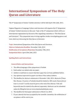
LED- Surface Emitting LED (SLED)
• Data rates less than 20 Mbps
• Short optical links with large NA fibres (poor coupling)
• Coupling lens used to increase efficiency
G Keiser 2000
Prof. Z Ghassemlooy
10
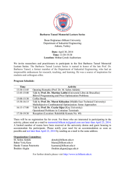
LED- Edge Emitting LED (ELED)
• Higher data rate > 100 Mbps
• Multimode and single mode fibres
G Keiser 2000
Prof. Z Ghassemlooy
11
LED - Spectral Profile
Intensity
1300-1550 nm
800-900
nm
65
45
15 0 15 45
65
Wavelength (nm)
Prof. Z Ghassemlooy
12
LED - Power Vs. Current Characteristics
5
4
3
2
1
SELED
Temperature
Linear region
ELED
50
Current I (mA)
Since P I, then LED can be intensity modulated by
modulating the I
Prof. Z Ghassemlooy
13
LED - Characteristics
Wavelength
800-850 nm
1300 nm
• Spectral width (nm)
30-60
50-150
• Output power (mW)
0.4-5
0.4-1.0
• Coupled power (mW)
- 100 um core
- 50 um core
0.1-2 ELED
0.3-0.4 SLED
0.01-0.05 SLED
0.05-0.15
- Single mode
0.04-0.08
0.03-0.07
0.003-0.04
• Drive current (mA)
50-150
100-150
• Modulation bandwidth
(MHz)
80-150
100-300
Prof. Z Ghassemlooy
14
Laser - Characteristics
• The term Laser stands for Light Amplification by Stimulated
Emission of Radiation.
• Could be mono-chromatic (one colour).
• It is coherent in nature. (I.e. all the wavelengths contained within
the Laser light have the same phase). One the main advantage of
Laser over other light sources
• A pumping source providing power
• It had well defined threshold current beyond which lasing occurs
• At low operating current it behaves like LED
• Most operate in the near-infrared region
Prof. Z Ghassemlooy
15
Laser - Basic Operation
Similar to LED, but based on stimulated light emission.
mirror 1
Mirrors used to
“re-cycle” phonons”
mirror 2
“LED”
coherent light
R = 0.90
R = 0.99
Three steps required to generate a laser beam are:
• Absorption
• Spontaneous Emission
Current density:
• 104 A/cm2 down to 10 A/cm2
• Stimulated Emission
Prof. Z Ghassemlooy
16
Absorption
When a photon with certain energy is incident on an electron in a semiconductor
at the ground state(lower energy level E1 the electron absorbs the energy and
shifts to the higher energy level E2.
The energy now acquired by the electron is Ee = hf = E2 - E1. Plank's law
E2
E1
E2
Incoming
photon
Ee = hf
Electron
E1
Initial state
E2
E1
Excited electron
final state
Prof. Z Ghassemlooy
17
Spontaneous Emission
• E2 is unstable and the excited electron(s) will return back to the
lower energy level E1
• As they fall, they give up the energy acquired during absorption
in the form of radiation, which is known as the spontaneous
emission process.
E2
E1
E2
Photon
Ee = hf
E1
Initial state
Prof. Z Ghassemlooy
18
Stimulated Emission
• But before the occurrence of this spontaneous emission process, if external
stimulation (photon) is used to strike the excited atom then, it will stimulate the
electron to return to the lower state level.
• By doing so it releases its energy as a new photon. The generated photon(s) is in
phase and have the same frequency as the incident photon.
• The result is generation of a coherent light composed of two or more
photons.
• In quantum mechanic – Two process: Absorption and Stimulated emission
E2
E1
E2
Ee = hf
Requirement:
Ee = hf
Ee = hf
E1
<0
Coherent light
Ee = hf
Light amplification: I(x) = I0exp(-x)
Prof. Z Ghassemlooy
19
Laser - Basic Operation
So we have a large number of electron inside a cavity, therefore need to talk about statistics.
Thus need to talk average rates of transition. I.e. what is the probability that a transition can
take place between two levels per unit time.
N2
The rate of absorption process is:
Transition probability from 1 to 2
[is a constant introduced by Einstein]
Occupation
probability of level 1
Photon density
In the cavity foe E21
Probability that
Lower level is empty
f1 and f2 are Fermi functions given as:
F1 and F2 are quasi Fermi levels (i.e., number of
electrons in the lower and upper levels,
respectively
Prof. Z Ghassemlooy
20
Laser - Basic Operation
The rate of spontaneous emission process is:
Transition probability from 2 to 1
[is a constant introduced by Einstein]
Probability that
Lower level is empty
Occupation
probability of level 2
The rate of stimulated emission process is:
Photon density
In the cavity foe E21
Transition probability
from 2 to 1
The rate of total emission process is (upper level is depopulated):
Prof. Z Ghassemlooy
21
Laser - Basic Operation
• At dynamic equilibrium
Absorption
=
emission
One need to solve this to determine
Prof. Z Ghassemlooy
22
The Rate Equations
Rate of change of
photon numbers = stimulated emission + spontaneous emission + loss
d
dt
Cn R sp
ph
Rate of change of
electron numbers = Injection + spontaneous emission + stimulated spontaneous
dn
dt
J
qd
n
sp
Cn
J is thecurrent density, Rsp is the rate of spontaneous emission, ph is the photon rate,
s spontaneous recombination rate, C is the constant
Prof. Z Ghassemlooy
23
Laser Diodes (LD)
I
Standing wave (modes) exists at
frequencies for which
L
L
i
,
i = 1, 2, ..
2n
Modes are separated by
c
f
Optical confinement
layers
2 nL
2 nL
i
In terms of wavelength separation
2
2 nL
Prof. Z Ghassemlooy
2 nL
i 1
2 nL
for i 1
i
2
f
c
24
LD - Spectral Profile
Intensity
Modes
Gaussian output
profile
5
3
1 0 1
3
5
Wavelength (nm)
Multi-mode
Prof. Z Ghassemlooy
25
LD - Efficiencies
Internal quantum efficiency
int
number of photons generated in the cavity
number of injected electrons
External quantum efficiency
External power efficiency
ext
ep
Pe
IE g
Pe
P
Where P = IV
Prof. Z Ghassemlooy
26
Power Vs. Current Characteristics
Temp.
5
4
3
2
1
LED
Stimulated
emission
(lasing)
Spontaneous emission
50
Current I (mA)
Prof. Z Ghassemlooy
Threshold current
Ith
27
LED & LD - Frequency Response
Magnitude (dB)
LED
LD
0
-3
1
10
100
1000
10,000
Frequency (MHz)
Prof. Z Ghassemlooy
28
LD - Single Mode
• Achieved by reducing the cavity length L from 250 m to 25 m
• But difficult to fabricate
• Low power
• Long distance applications
Types:
• Fabry-Perot (FP)
•Distributed Feedback (DFB)
• Distributed Bragg Reflector (DBR)
• Distributed Reflector (DR)
Prof. Z Ghassemlooy
29
Laser - Fabry-Perot
Strong optical feedback in the longitudinal direction
Multiple longitudinal mode spectrum
Ppeak
“Classic” semiconductor laser
– 1st fibre optic links (850 nm or 1300 nm)
– Short & medium range links
Key characteristics
–
–
–
–
–
–
–
Wavelength: 850 or 1310 nm
Total output power: a few mw
Spectral width: 3 to 20 nm
Mode spacing: 0.7 to 2 nm
Highly polarized
Coherence length: 1 to 100 mm
Small NA ( good coupling into fiber)
Agilent Technology
Prof. Z Ghassemlooy
P
Threshold
I
250-500 um
Cleaved faces
5-15 um
30
Laser - Distributed Feedback (DFB)
No cleaved faces, uses Bragg Reflectors for lasing
Single longitudinal mode spectrum
High performance
– Costly
– Long-haul links & DWDM systems
Key characteristics
–
–
–
–
–
–
Corrugated feedback Bragg
Wavelength: around 1550 nm
Total power output: 3 to 50 mw
Spectral width: 10 to 100 MHz (0.08 to 0.8 pm)
Sidemode suppression ratio (SMSR): > 50 dB
Coherence length: 1 to 100 m
Small NA ( good coupling into fiber)
P peak
SMSR
Agilent Technology
Prof. Z Ghassemlooy
31
Laser - Vertical Cavity Surface
Emitting Lasers (VCSEL)
Distributed Bragg reflector mirrors
– Alternating layers of semiconductor material
– 40 to 60 layers, each / 4 thick
– Beam matches optical acceptance needs of fibers more closely
Key properties
–
–
–
–
–
Wavelength range: 780 to 980 nm (gigabit ethernet)
Spectral width: <1nm
Total output power: >-10 dBm
Coherence length:10 cm to10 m
Numerical aperture: 0.2 to 0.3
Laser output
p-DBR
active
n-DBR
Agilent Technology
Prof. Z Ghassemlooy
32
Laser diode - Properties
Property
Multimode
Single Mode
• Spectral width (nm)
1-5
< 0.2
• Output power (mW)
1-10
10-100
0.1-5
1-40
1-40
25-60
• Drive current (mA)
50-150
100-250
• Modulation bandwidth
(MHz)
2000
6000-40,000
• Coupled power (W)
- Single mode
• External quantum efficiency
Prof. Z Ghassemlooy
33
Comparison
LED
Laser Diode
Low efficiency
Slow response time
Lower data transmission rate
Broad output spectrum
In-coherent beam
Low launch power
Higher distortion level at the
output
Suitable for shorter
transmission distances.
Higher dispersion
Less temperature dependent
Simple construction
Life time 107 hours
High efficiency
Fast response time
Higher data transmission rate
Narrow output spectrum
Coherent output beam
Higher bit rate
High launch power
Less distortion
Suitable for longer transmission
distances
Lower dispersion
More temperature dependent
Construction is complicated
Life time 107 hours
Prof. Z Ghassemlooy
34
Type of Data Communications
Broadcasting communications
– Visible light communications
– Infrared communications
Duplex communications (bidirectional)
– Infrared, high speed
– Cellular structure
– Narrow FOV
Prof. Z Ghassemlooy
35
Transmitter Design
Electrical driver
– DC driver
• VLC: sufficient light for illumination
• Laser: lasing level
• Ensuring linear modulation
– AC driver (modulator)
– Modulation depth
Transmitter Field-of-View (FOV)
– Link range
– Coverage
Modulation schemes
Prof. Z Ghassemlooy
36
Modulation
The process transmitting information via light carrier
(or any carrier signal) is called modulation.
• Direct Intensity (current)
• Inexpensive (LED)
• In LD it suffers from chirp up to 1 nm (wavelength variation
due to variation in electron densities in the lasing area)
DC
RF modulating
signal
R
I
Intensity Modulated
optical carrier signal
• External Modulation
Prof. Z Ghassemlooy
37
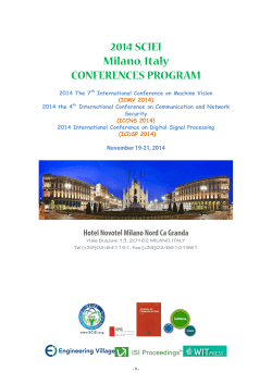
Direct Intensity Modulation- Analogue
LED
LD
Input signal
G Keiser 2000
Prof. Z Ghassemlooy
38
Direct Intensity Modulation- Digital
LD
Optical power
Optical power
LED
i
i
Time
t
Time
t
Prof. Z Ghassemlooy
39
Driver Circuit
Type
– Analogue (Transistors)
– Digital (Logic gate, opamp)
Circuit
– Discrete (transistor, R, L, C)
• Flexible to build and test but bulky
• Low speed, problem with parasitic, matching
– Integrated circuit (IC)
• Compact, cheap
• Well calibrated and tested
• High speed and good coupling
Prof. Z Ghassemlooy
40
Bias Tee
• To couple to DC and AC signals to drive LED/LD
• To separate the DC and AC sources
Some issues need to know
- Leaked ratio
- Impedance matching
- Operational bandwidth
Prof. Z Ghassemlooy
41
LED Driver - VLC
Transmitter
Optical receiver
Concentrator PD
Input
data signal
Preamplifier
LPF
L
DC
R
Recovered
data signal
Modulators LED array
Resonant
Capacitor (C) Bias Tee
A
High-speed
buffer
Inductance (Lseries)
DC arm
Signal
Luxeon LED, R
Z
DC bias current
from Laser driver
Individual LED driving circuit
Prof. Z Ghassemlooy
42
Laser Driver
Let’s examine the high speed driver circuit
- Impedance matching
- Proper biasing
- Lasing point
- Modulation depth
- Bias Tee
- Feedback
- Amplification gain
control
- Power monitoring
http://datasheets.maxim-ic.com/en/ds/MAX3869.pdf
Prof. Z Ghassemlooy
43
External Modulation
• For high frequencies 2.5 Gbps - 40 Gbps
• AM sidebands (caused by modulation spectrum) dominate
linewidth of optical signal
DC
MOD
R
Modulated optical
carrier signal
I
RF (modulating signal)
Prof. Z Ghassemlooy
44
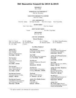
Modulation Bandwidth
In optical fibre communication the modulation bandwidth
may be defined in terms of:
• Eelectrical Bandwidth Bele - (most widely used)
• Optical Bandwidth Bopt - Larger than Bele
Optical 3 dB point
G Keiser 2000
Prof. Z Ghassemlooy
45
© Copyright 2026 Paperzz