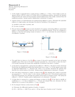
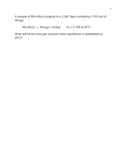
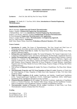
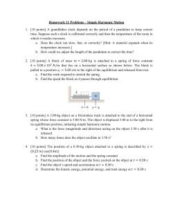
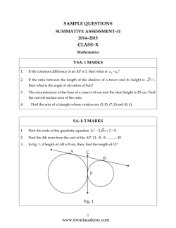
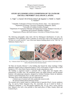
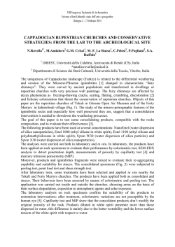
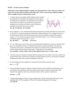
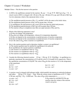
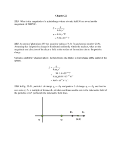
Mukavemet 1 Notları
Buradaki
notlar
“Mechanics of Materials by R.C. Hibbeler" adlı
4
C H A P Tbüyük
ER 1
S Toranda
RESS
kitaptan çevrilerek alınmıştır. Notlar bilgilendirme amaçlı olup öğrencilerimize
adı geçen kitabı satın almaları önerilmektedir.
Historical Development. The origin of mechanics of materials
1
dates back to the beginning of the seventeenth century, when Galileo
performed experiments to study the effects of loads on rods and beams
made of various materials. However, at the beginning of the eighteenth
Giriş
century, experimental methods for testing materials were vastly
improved,karşı
and at oluşturduğu
that time manydirenç
experimental
theoretical studies
Mukavemet adı ile malzemenin yüklere
veya and
dayanım
in this subject were undertaken primarily in France, by such notables as
kastedilmektedir. Mukavemet dersi yabancı
dilde “Strength
of Materials”
Saint-Venant,
Poisson, Lamé,
and Navier.ve “Mechanics of
Over the years, after many of the fundamental problems of mechanics
Materials” gibi adlar altında verilmektedir.
Strengthhad
kelimesi
olarak tercüme
of materials
been dilimize
solved, itdayanım
became necessary
to use advanced
mathematical and computer techniques to solve more complex problems.
edilebilir. Mechanics kelimesi ise kuvvetlerin cisimler üzerindeki etkilerini inceleyen bilim dalı
As a result, this subject expanded into other areas of mechanics, such as the
theory of elasticity and the theory of plasticity. Research in these fields
olan mekanik olarak tercüme edilir.
is ongoing, in order to meet the demands for solving more advanced
Mukavemet dersinde çeşitli malzemelerden
üretilmiş
elemanların çeşitli etkiler/tesirler ve
problems
in engineering.
kuvvetler altındaki davranışı, analizi ve tasarımı/dizaynı incelenecektir. Tasarım, yapısal bir
elemanının üretileceği malzemeyi ve sahip olacağı boyutları ve geometriyi, kendisine tesir
of a Deformable
Body
etmesi beklenen yüklere/kuvvetlere 1.2
belirli Equilibrium
güvenlik sınırlarında
dayanacak şekilde
Sincegerçekleştirilebilmesi
statics has an important için
role inyapılması
both the development
and application
belirlemektir. Analiz ise tasarım işlemin
gereken tüm
of mechanics of materials, it is very important to have a good grasp of its
fundamentals. For this reason we will review some of the main principles
of statics that will be used throughout the text.
işlemler/hesaplamalardır.
Mukavemet dersinde eksenel kuvvet, eğilme ve burulma momenti gibi tesirler incelenecektir.
External Loads. A body is subjected to only two types of external
loads; namely, surface forces or body forces, Fig. 1–1.
Kuvvet Dengesi
Concentrated force
idealization
s
Surface
force
G
C
FR
W
w(s)
Linear distributed
load
#
Body
force
Fig. 1–1
Surface Forces. Surface forces are caused by the direct contact of one
body with the surface of another. In all cases these forces are distributed
over the area of contact between the bodies. If this area is small in
comparison with the total surface area of the body, then the surface force
can be idealized as a single concentrated force, which is applied to a point
on the body. For example, the force of the ground on the wheels of a
bicycle can be considered as a concentrated force. If the surface loading is
applied along a narrow strip of area, the loading can be idealized as a
linear distributed load, w(s). Here the loading is measured as having an
intensity of force/length along the strip and is represented graphically by a
series of arrows along the line s. The resultant force FR of w(s) is
equivalent to the area under the distributed loading curve, and this
resultant acts through the centroid C or geometric center of this area. The
loading along the length of a beam is a typical example of where this
idealization is often applied.
Dış Yükler: Tekil Yükler (N), Alan Üzerine Yayılı Yükler (N/m2), Çizgisel Yayılı Yükler (N/
m)
Mesnet Reaksiyonları: Cismin düşey, yatay veya dönme hareketlerinin engellendiği
doğrultularda oluşan kuvvet tepkileri.
#1
in order to enable free rotation at their
connections. These supports exert a force on
a member, but no moment.
(1–1)
the surface. Hence, the roller exerts a normal force F on the member at
©Fthe= roller,
0
its point of contact. Since the member can freely rotate about
a couple moment cannot be developed on the member. ©MO = 0
STRESS
TABLE 1–1
FEquilibrium
Here, ©Reaction
represents the
ofrequires
allofthe
forces
body, and
Equations
of Equilibrium.
of asum
body
both acting on the Reaction
Type of connection
Type
connection
© MO isthe
the body
sum of
thetranslating
moments of
the forces about any point O
a balance of forces, to prevent
from
orall
having
either
on
or
off
the
body.
If
an
x,
y,
z
coordinate
system is established
accelerated motion along a straight or curved path, and a balance of
Fy resolved
with
the
origin
at
point
O,
the
force
and
moment
vectors
can be
u rotating. These conditions can be
moments, to prevent
the body from
u
F
into
components
along
each
coordinate
axis
and
the
above
two
Fx
expressed mathematically by two vector equations
equations can be written in scalar form as six equations, namely,
Cable
©F = 0
©MO = 0
F
Roller
Two unknowns: Fx, Fy
External pin
One unknown: F
Fy
©Fy = 0 (1–1)
©Fz = 0 Fx
©My = 0 ©Mz = 0
©Fx = 0
©Mx = 0
(1–2)
Internal pin
One unknown: F
Two unknowns: Fx, Fy
Here, © F represents the sum of all the forces acting on the body, and
M
Fy
Often
inofengineering
practice
loading
© MO is the
sum of the
all both
the forces
abouttheany
pointon
Oa bodyFcan be represented
s of Equilibrium.
Equilibrium
of amoments
body
requires
x
asIfaan
system
coplanar forces.
If is
this
is the case, and the forces lie in the
either on
off the
body.
x, y,orzofhaving
coordinate
system
established
f forces, to prevent
theorbody
from
translating
F plane,
then
the
conditions
equilibrium of the body can be
u a balance
the origin
at pointpath,
O,x–y
the
force
and
moment
vectors canfor
be resolved
motion along with
a straight
or
curved
and
of
Three unknowns: Fx, Fy, M
Smooth support
Fixed support
One unknown: F
withcan
only
scalarthe
equilibrium
equations; that is,
into# components
each
coordinate
axis and
above two
prevent the body
from rotating.along
Thesespecified
conditions
bethree
can equations
be written in scalar form as six equations, namely,
athematically equations
by two vector
Denge Denklemleri:
#
©F = 0
©MO = 0
#
©Fx = 0
©Mx = 0
©Fy = 0
©Fz = 0
(1–1)
©My = 0 ©Mz = 0
#
©Fx = 0
©Fy = 0(1–2)
©MO = 0
1.2
Serbest Cisim Diyagramı
(1–3)
7
EQUILIBRIUM OF A DEFORMABLE BODY
epresents the sum
of all
forcesF4 acting
on the
the loading
body, and
Often
in the
engineering
practice
on a body can be represented
MR
Here all the moments are summed about point O and so they
will be
Fof
3
sum of the moments
all
the
forces
about
any
point
O and the forces lie in the
as a system of coplanar forces. If this is
the case,
directed along the z axis.
off the body. x–y
If anplane,
x, y, zthen
coordinate
system isfor
established
the conditions
equilibrium of the body can be
Successful application of the equations of equilibrium requires
in
at
point
O,
the
force
and
moment
vectors
can
be
resolved
n order to design
the horizontal
members
specified
with only
three scalar equilibrium
equations; that is,
complete specification of all the known and unknown forces that act on
of
this building
is first necessary
to and
nents
along frame,
each it coordinate
axis
the above two
the body, and so the best way to account for all these forces is to draw
indbethe
internal
at various
n
written
inloadings
scalar form
as sixpoints
equations,
namely,
section
the body’s free-body diagram.
along their length.
O
©Fx = 0
©Mx = 0
©Fy = 0
F1
©My = 0
(a)
#
©Fz = 0
F2
©Mz = 0
1.2
©Fx = 0
©Fy = 0
F
©MO = 0(1–2) 1
1
FR
O
(1–3)
F1
F2
(b)
EQUILIBRIUM OF A DEFORMABLE BODY
Fig. 1–2
7
F2
(c)
4 adet dış kuvvet ile dengede bulunan cisimden bir kesim alalım. Bu kesime genellikle enkesit
MRO and so they will be
Here the
all loading
the moments
are can
summed
about point
ngineering practice
ondenilir.
a body
be represented
(cross
section)
1
directed
along
thecase,
z axis.
of coplanar forces.
If this
is the
and the forces lie in the
Successful
applicationof of
equations
hen
the conditions
for equilibrium
thethe
body
can be of equilibrium requires FR
tal members
complete
specification
of
all
the
known
and unknown forces that act on
to scalar equilibrium equations; that is,
hnecessary
only three
arious points the body, and so the best way to account for all these forces is to draw
O
section
the body’s
free-body
diagram.
Internal
Resultant
Loadings. In mechanics of materials,
statics
is primarily used to determine the resultant loadings that act within a
body. For example, consider the body shown in Fig. 1–2a, which is held in
©Fx = 0
equilibrium
by the four external forces.∗ In order to obtain the internal
0
(1–3)the
F1©Fy = acting
F1 body, it is necessary to pass
loadings
on a specificFregion within
F2
2
©M
=
0
an imaginary
section or “cut” through the region where
the
internal
O
(c)
(b)
# loadings are to be determined. The two parts of the body are then
Fig.a 1–2
separated, and
free-body diagram of one of the parts is drawn, Fig. 1–2b.
Kesim
sonrası
veya üst
parçalardan
birini force
dikkate
alalım.
Notice that
therealt
is actually
a distribution
of internal
acting
on the Burada
“exposed” area of the section. These forces represent the effects of the
alıyoruz.
moments are summed
about point O and so they will be
material of the top part of the body acting on the adjacent material of
ng the z axis.
the bottom part.
application of the equations of equilibrium requires
Although the exact distribution of this internal loading may be unknown,
ecification of all the known and unknown forces that act on
we can use the equations of equilibrium to relate the external forces on the
so the best wayIntomechanics
account for
all these forces
is to draw
td Loadings.
of the
materials,
bottom part of
body tostatics
the distribution’s resultant force and moment,
ee-body
diagram.
etermine the resultant
loadings
within
a O on the sectioned area, Fig. 1–2c. It
FR and
MRO, atthat
anyact
specific
point
sider the body shown
in
Fig.
1–2a,
which
is
held
in
will be shown in later portions of the text that point O is most often
O
alt parçayı dikkate
#2
7
EQUILIBRIUM OF A DEFORMABLE BODY
MRO
1
FR
O
F1
F2
#
F2
(c)
Kesim bölgesinin ağırlık merkezinde kuvvetlerin bileşkelerini gösterelim.
Torsional
Moment
T
MRO
Normal
N Force
FR
statics
within a
held in
nternal
to pass
nternal
e then
g. 1–2b.
on the
of the
erial of
Bending M
Moment
F2
O
V
Shear
Force
F1
#
İç kuvvet
Fig. 1–2
(cont.)
FR
F2
(d)
bileşkeleri MRO ve FR nin dik eksenlerdeki bileşenlerini gösterelim:
Normal Kuvvet (N): Kesim yüzeyine dik kuvvet.
Kayma/Kesme Kuvveti (V): Kesim yüzeyine paralel kuvvet.
known,
Burulma
momenti/Tork
(T):the
Kesite dik eksen etrafında moment/döndürme kuvveti
text we will
show how to relate
sons.
on the Later in this
FR and MRO, to the distribution of force on the
gs,
oment,
Eğilme momenti (M): Kesite paralel eksenler etrafında moment
and thereby
develop equations that can be used for
1–2c.
It
To do this, however, the components of FR and MRO
tgn.
often
mal
and perpendicular to the sectioned area must be
choose
1.21.2 EQUILIBRIUM
OFOF
AD
BODY
EQUILIBRIUM
A EFORMABLE
DEFORMABLE
BODY
Düzlem
Durumu
(2 Boyutlu Analiz)
1–2d.
Four different
types ofYükleme
resultant loadings
can then
ng and
1.2 EQUILIBRIUM OF A DEFORMABLE
BODY
lows:
ered is
1.2
EQUILIBRIUM OF A9DyEFORMABLE BODY
section
section
F2 F2
yShear
F3 F3
ember.
Shear
F2 F2
Force
Force
N. This force acts perpendicular
to
the
area.
It
is
V
ction
y
V
section
y
F3
F2
Shear
F3
Bending
Shear
ever the external loads tend to Fpush or pull on the two Force
O Bending
1 MOMMoment
2
F2
Force
Moment
body.
V
V
x
O
99
9
11
1
x
O
MO Bending
MO Bending N N
Moment
Moment Normal
Normal
. The shear force lies in the
of the OF
area
it Fis BODY x F1 F
1.2 plane
EQUILIBRIUM
A Dand
EFORMABLE
9
O
x Force
O
Force
1
4 F4
N
N
the external
loads
F1
# tend to cause the(a)two segments of Normal
(b)
(b)
Normal
herefore
(a)
over one another.
F1
Force
F1
Force
F4
y
F4
F3
Shear
Fig.
1–3
(b)
Fig.
1–3
(b)
1
a)
F2
Force
(a)
ment or torque, T. This effect is developed
when the
V
Loadings.
If If
the
body
subjected
toto
a coplanar
system
ofof
Coplanar
Loadings.
the
body
subjected
a coplanar
system
Fig. 1–3 of
Mrespect
Fig. is
1–3
end to twist oneCoplanar
segment
the body with
tois
O Bending
Moment shear-force,
forces,
Fig.
1–3a,
then
only
normal-force,
and
bendingmoment
forces,
Fig.
1–3a,
then
only
normal-force,
shear-force,
and
bendingmoment
an axis perpendicular to the area.
x Fig. 1–3b. If we use the x, y, z
Oatsystem
. If theCoplanar
body iscomponents
subjected
towill
awill
coplanar
of
exist
Loadings.
If
the
body
is section,
subjected
to a coplanar
system
components
exist
atthe
the
section,
Fig.
1–3b. If we
use ofthe x, y, z
N
nly normal-force,
shear-force,
and
bendingmoment
coordinate
as
shown
onon
the
left
segment,
NN
can
bebe
obtained
byby
forces, Fig.
1–3a, thenaxes,
only
normal-force,
shear-force,
andthen
bendingmoment
Normal
coordinate
axes,
as
shown
the
left
segment,
then
can
obtained
ment,
Theapplying
moment
isthe
caused
by
the
Fbending
Force
1 will
atF4theM.
section,
Fig.
1–3b.
If
we
use
x,
y,
z
©F
=
0,
©F
=
0.
and
V
can
be
obtained
from
Finally,
the
components
exist
at
the
section,
Fig.
1–3b.
If
we
use
the
x,
y,
z
x
y
©F
=
0,
©F
=
0.
applying
and
V
can
be
obtained
from
Finally,
the
y
# body aboutx an axis lying within the
at
to left
bend
the
(b)
wntend
on the
segment,
N canon
obtained
by
Mbe
bending
moment
can
besegment,
summing
moments
coordinate
axes,then
as
shown
left
then by
Nby
can
be obtained
by about
Othe
M
bending
moment
can
bedetermined
determined
summing
moments
about
F1 F1
O
. V can be obtained
©F
=axis),
0. #Finally,
d
from
=the
O
(the
z yV
©M
toyto=
eliminate
the
moments
©F
0, (the
©F
0. Finally,
applyingpoint
and
can
be©M
obtained
the
O O
=0, 0,infrom
point
zaxis),
inorder
order
eliminate
the
moments
x =O
#
#
1–3 caused
can beFig.
determined
byby
summing
moments
about
the
unknowns
N
and
V.
M
bending
moment
can
be
determined
by
summing
moments
about
caused
by
the
unknowns
N
and
V.
O
te©M
thatOgraphical
representation
of a moment
or torque is
=
0, inOorder
eliminate
the moments
point
(the ztoaxis),
©M
O = 0, in order to eliminate the moments
yns
is
subjected
to
a
coplanar
system
of
mensions
as
a
vector
with
an
associated
curl.
By
the rightN and
V. by the unknowns
caused
N and V.
Important
Points
Important
Points
rce, shear-force,
bendingmoment
humb
gives the and
arrowhead
sense
of this vector and the
on, Fig.
If weforuse
the x,(twisting
y, z
dicate
the1–3b.
tendency
rotation
or bending).
tt segment,
Points
Points
thenImportant
N can
be
obtained
by
• •Mechanics
ofof
materials
is is
a study
ofof
the
relationship
between
the
Mechanics
materials
a study
the
relationship
between
the
0. Finally,
obtained from ©Fy =external
the
loads
applied
toto
a body
and
the
stress
and
strain
caused
external
loads
applied
a body
and
the
stress
and
strain
caused
mined
summing
moments
about
erials isby
a•
study
of the
between
the
byrelationship
the
internal
loads
within
body.
Mechanics
ofthe
materials
is loads
a study
of the
relationship
between the
by
internal
within
the
body.
#3
İç Kuvvetlerin İşaretleri
1.2
EQUILIBRIUM OF A DEFORMABLE BODY
XAMPLE 1.1
#
1.2
11
EQUILIBRIUM OF A DEFORMABLE BODY
Determine the resultant internal loadings acting on the cross section
at C of the cantilevered beam shown in Fig. 1–4a.
# EXAMPLE 1.1
1
Determine the resultant internal loadings acting on the cross section
at C of the cantilevered beam shown in Fig. 1–4a.
270 N/m
270 N/m
A
B
#
3m
A
C
C
3 m(a)
B
6m
6m
(a)
Şekilde verilen çıkmalı kirişte C noktasından
alınan enkesitteki iç kuvvetleri hesaplayınız.
Fig. 1–4 Fig. 1–4
SOLUTION
SOLUTION Çözüm:
Support Reactions. The support reactions at A do not have to be
Kesim yaptıktan
sonra hangi
taraf için
serbest
cisim
diyagramını
Support Reactions.
The support
reactions
at A
do not
have
to be çizmek ve540içN kuvvetleri
determined if segment CB is considered.
540 N
determined ifhesaplamak
segment
CB
iskolay
considered.
180 N/m
daha
olacaktır?
Free-Body
Diagram.
The free-body diagram of segment CB is shown
in Fig. 1–4b.
It isfree-body
important to
keep theof
distributed
the
180 N/m
MC
Free-Body Diagram.
The
diagram
segmentloading
CB is on
shown
Birsegment
yayılı yükün
şiddeti
nasıl hesaplanır?
until after
the section
is made. Only then should this loading
n Fig. 1–4b. It be
is important
to keep
the
distributed
loading
on
theNC
MCC
a single
resultant
force.
that the
intensity
of the
Yayılıreplaced
yükün byşiddeti/bileşkesi
hangiNotice
noktadan
etki
ettirildiğinde,
denge
denklemlerinin
segment until after
the section
is Cmade.
Only
then should
thisFig.
loading
distributed
loading at
is found
by proportion,
i.e., from
1–4a,
VC
2m
4m
The
magnitude
ofofthe
m = 1270
N>m2>9yayılı
m, w =
180 N>m.
yazılması
sırasında
yükün
yerine
(Not:
Kesme
be replaced by
aw>6
single
resultant
force.
Notice
that
thegeçer?
intensity
the NC kuvveti Cve moment
(b)
resultant of the distributed load is equal to the area under the
distributed loading
at curve
C is (triangle)
found by
proportion,
i.e.,
fromalınmadan
VC
diyagramlarının
çizilmesi
sırasında
yayılı yük
dikkate
loading
and
acts through
the
centroid
ofFig.
this 1–4a,
area.diyagram çizilemez.)
2m
1
1
of the
w>6 m = 1270 N>m2>9
w = 180 N>m. The magnitude
Thus, F = m,
2 1180 N>m216 m2 = 540 N, which acts 3 16 m2 = 2 m from
Kuvvetshown
birimiin1kgf
= 9.81Newton
(b)
Fig. 1–4b.
resultant of theC asdistributed
load is equal to the area under the
Equations ofand
Equilibrium.
Applying
equations of
of equilibrium
oading curve (triangle)
acts through
thethecentroid
this area.
we
have
1
1
Thus, F = 21180 N>m216 m2 = 540 N, which acts 316 m2 = 2 m from
+ ©F = 0;
:
-NC = 0
x
C as shown in Fig.
1–4b.
Ans.
NC = 0
Equations of Equilibrium. Applying the
equations of equilibrium
+ c ©Fy = 0;
VC - 540 N = 0
we have
540 N
Ans.
VC = 540 N
135 N
+ ©F = 0;
:
-N = 0
x
+ c ©Fy = 0;
d+ ©MC = 0;
C - 540 N12 m2 = 0
-M
C
NCM=C =0 - 1080 N # m
90 N/m
Ans.
Ans.
= 0 that MC acts in the opposite
NOTE: The V
negative
signNindicates
C - 540
direction to that shown on the free-body diagram. Try solving this
Ans.
VC =AC,
540
problem using segment
by N
first obtaining the support reactions
at
A, which are given in Fig. 1–4c.
4m
180 N/m
MC
1215 N
3645 N!m
B
A
1m
C
#4
1.5 m VC
0.5 m
540
(c)135 N
NC
N
3m
6m
(a)
Fig. 1–4
SOLUTION
Support Reactions.
The support reactions at A do not have to be
Serbest
Cisim Diyagramı
ot have to be determined if segment CB is considered.
540 N The free-body diagram of segment CB is shown
Free-Body Diagram.
1–4b.
It is important to keep the distributed loading on the
N/m
t CB is shown in Fig.180
segment until after the section is made. Only then should this loading
ading on the
MC
be replaced
by a single resultant force. Notice that the intensity of the
d this loading distributed loading at C is found by proportion, i.e., from Fig. 1–4a,
NC
C
B
tensity of the w>6
m = 1270 N>m2>9 m, w = 180 N>m. The magnitude of the
have
be resultantVCof the distributed load is equal to the area under the
om
Fig.to1–4a,
2m
m through the centroid of this area.
(triangle)
and4acts
540
N
ude of the # loading curve
1
1
F = 21180 N>m216
(b) m2 = 540 N, which acts 316 m2 = 2 m from
a under
the Thus,180
N/m
CB
is shown
C as shown in Fig. 1–4b.
of this
ding
on area.
the Equations
MC
of Equilibrium. Applying the equations of equilibrium
= 2loading
m from Kuvvet Denge
Denklemleri
this
we have
N
C
B
nsity of the C+
: ©Fx = 0;
-NC = 0
mf equilibrium
Fig. 1–4a,
VC
2m
4 m NC = 0
Ans.
de of the
540 N
180 N/m
MC
NC
C
VC
B
2m
4m
(b)
(b) VC - 540 N = 0
under the + c ©Fy = 0;
f this area.
Ans.
= 2 m from
VC = 540 N
d+ ©MC = 0;
Ans.
-MC - 540 N12 m2 = 0
MC = - 1080 N # m
equilibrium #
Ans.
135 N
90 N/m
Ans.
180 N/m
MC
1215 N
A
540 N
135 N sign indicates that MC acts in the opposite 3645 N!m
NOTE: The negative
direction
that shown on the free-body diagram. Try solving this
90to
N/m
1m
180
N/m
C
noktasındaki
iç Bkuvvetleri
hesaplamak
için
C noktasının
solundaki parçayı
problem
using
segment
AC, by first
obtaining
the
support
reactions
at
1.2 EQUILIBRIUM
OF A D
EFORMABLE
ODY
15
MC
1215 N
Ans.
Ans. A, which are given in Fig. 1–4c.
olsaydık:
A
540 N
NC
C
1.5 m VC
0.5
m
dikkate
almış
(c)
NC
C
3645 mesnet
N!m
the opposite Önce
reaksiyonlarını hesaplamamız gerekecekti.
1
1.5 m VC
y solving this
1 m 540 N
Ans.
135 N 0.5 m
tcross
reactions
at
section
of 2 kg>m and
le moment of
(c)
90 N/m
180 N/m
MC
Ans.
1215 N
he opposite 3645 N!m
solving
so we dothis
not
reactions at #
A
1m
NC
C
1.5 m VC
0.5 m
(c)
1.2
15
EQUILIBRIUM OF A DEFORMABLE BODY
at B and the
EXAMPLE 1.5
The resultant #
med to act in
Determine the resultant internal loadings acting on the cross section
he centroid of
at B of theCpipe shown in Fig. 1–8a. The pipe has a mass of 2 kg>m and
is subjected to both a0.75
vertical
force of 50 N and a couple moment of
ent of pipe is
m
1
70 N # m at its end A. It is fixed to the wall at C.
B
N
25 N
gment.
equations of
#
Ans.
Ans.
Ans.
10.25 m2 = 0
0.5 m
D
SOLUTION
N be solved by considering segment AB, so we do not
The problem50
can
need to calculate the support
1.25 m reactions at C.
Free-Body Diagram. The x, y, z axes are established at B and the
A
free-body diagram
of segment AB is shown in Fig. 1–8b. The resultant
N!m
force70and
moment components at the section are assumed to act in
(a)
the positive coordinate
directions and to pass through the centroid of
the cross-sectional area at B. The weight of each segment of pipe is
z
calculated as follows:
WBD = (F
12 kg>m210.5
m219.81 N>kg2 = 9.81 N
B)z
(MB=)z 12 kg>m211.25 m219.81 N>kg2 = 24.525 N
(FB)W
9.81 N
y AD
These forces
themcenter of gravity of each segment.
(MB)yact through
0.25
(M
)
0.25 Applying
m
x Equilibrium.
Equations Bof
the six scalar equations of
B
(F
)
24.525
N
equilibrium,
we
have∗
B x
C
0.75 m
0.5 m
D
B
50 N
#5
1.25 m
70 N!m
A
B
N
D
EXAMPLE 1.550 N
5N
1.25 m
ment.
Determine the resultant internal loadings acting on the cross section
A in Fig. 1–8a. The pipe has a mass of 2 kg>m and
equations of at B of the pipe shown
is subjected
to both a vertical force of 50 N and a couple moment of
70
N!m
Şekilde
# verilen boru sistemi C noktasından ankastre mesnetlidir. B noktasındaki iç kuvvetleri
1
It is fixed to the wall at C.
70 N m at its end A.(a)
Ans. hesaplayınız. Borunun metresi 2 kg dır.
SOLUTION
z by considering segment AB, so we do not
Ans. The problem can be solved
Ans.
need to calculate the support reactions at C.
(FB)z
Free-Body Diagram. The
x, y, z axes are established at B and the
(M
z
free-body diagram
ofB)segment
(FB)y
9.81AB
N is shown in Fig. 1–8b. The resultant
force and moment
components
at the section are assumed to act in
(MB)y
0.25 m
the positive coordinate
directions
andmto pass through the centroid of
(MB)x
B at B. The0.25
the cross-sectional area
weight of each segment of pipe is
(F )
24.525 N
calculatedBasx follows:
50
0.625m219.81
m
y N>kg2 = 9.81 N
WN = 12 kg>m210.5
0.25 m2 = 0
Ans.
C
0.75 m
m2 = 0
BD
x
WAD = 12 kg>m211.25 m219.81 N>kg2 = 24.525 N
Ans.
0.625 m
Ans. These forcesAact through the center of gravity of each segment.
Equations
of Equilibrium. Applying the six scalar equations of
70 N·m
2 indicate? #
equilibrium, we have∗
(b)
Ans.
©Fx = 0;
1FB2x = 0
Ans.
©Fy = 0;
(FB)y = 0
Fig. 1–8
©Fz = 0;
1FB2z - 9.81 N - 24.525 N - 50 N = 0
Ans.
1FB2z = 84.3 N
#
©1MB2x = 0;
1MB2x + 70 N m - 50 N 10.5 m2
- 24.525 N 10.5 m2 - 9.81 N 10.25 m2 = 0
Ans.
1MB2x = - 30.3 N # m
B y
e shear force
moment is
is MB =
nitude of each
on of the force.
e, with positive
#
©1MB2y = 0; (MB)y + 24.525 N 10.625 m2 + 50 N 11.25 m2 = 0
Ans.
(MB)y = - 77.8 N # m
Ans.
©1MB2z = 0;
1MB2z = 0
NOTE: What do the negative signs for 1MB2x and 1MB2y indicate?
Note that the normal force NB = (FB)y = 0, whereas the shear force
is VB = 21022 + 184.322 = 84.3 N. Also, the torsional moment is
(MB)y = 77.8 N # m
0.5 m
D
B
50 N
1.25 m
A
70 N!m
(a)
z
(FB)z
(FB)y
(MB)z
(MB)y
(MB)x
(FB)x
B
24.525 N
50 N
9.81 N
0.25 m
0.25 m
0.625 m
y
x
0.625 m
70 N·m
A
(b)
Fig. 1–8
and the bending moment is MB =
TB =
2130.322 + 1022 = 30.3 N # m.
*The magnitude of each moment about an axis is equal to the magnitude of each
force times the perpendicular distance from the axis to the line of action of the force.
The direction of each moment is determined using the right-hand rule, with positive
moments (thumb) directed along the positive coordinate axes.
#6
© Copyright 2026 Paperzz