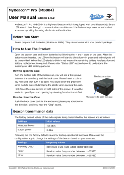
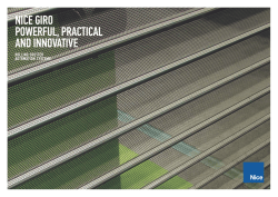
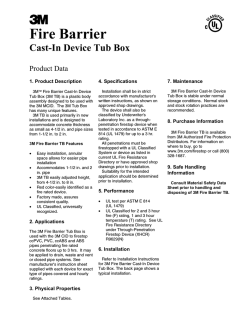
Conventional Audible Visual Devices
Sounders
> Product Overview
KAC’s conventional ENscape sounder is a high quality device designed to alert building occupants of an emergency.
The product features a new folded horn design which provides outstanding sound output at low current draw.
With its modern design, global tone set and extensive installer-friendly features, the ENscape sounder is the
logical choice for specifiers, OEMs, installers and distributors.
> ENscape Sounder Benefits
Simple, Fast, Flexible Installation
• Modern design eliminates need for device orientation.
• First fix capability allowing electrical continuity testing
prior to device fitting.
• Deep base option with multiple cable entries for flexible installation.
• Designed with full range of common fixing centres.
• Positive fit engagement & feedback of base with device
for easy installation.
•
•
•
•
•
•
Approved to EN54-3.
Superior sound output and low current consumption.
32 tones all approved to EN54-3.
Adjustable volume settings.
Two stage sounders enable alert and alarm sequences
to be set for phased evacuation.
Synchronised sound output.
Quality & Reliability
Universal Device
•
•
•
•
Outstanding Performance
Suitable for wall and ceiling mount applications.
Global tone set: 32 tones including a new bell tone.
Range of installation and base options, for indoor and applications up to IP65.
Optimised for 12V and 24V systems, making the range suitable for use in fire & security applications.
•
•
Independently approved to all required standards:
- Manufacturing: Construction Products Regulation (CPR).
- Product performance: Approved to EN54-3
- Environmental: RoHS, WEEE
Product range supports system approval.
> Introducing the Range
Device
Approvals
ENscape Sounders
EN54-3
Body Colour
Red
White
Installation Options
Standard
device
First
Fix
Base Options
Environmental
Compliance
Low Profile or
Deep/IP65
RoHS/ WEEE
CAV-S
Rev. No.1
Sounders – Technical Specification
Environmental Specification
Electrical Specification
Operating Temperature: Relative Humidity: Ingress Protection: For RoHS & WEEE
Operating Voltage: 9 to 29VDC
(Approved to EN54-3 @ 9-14V and 18-29V)
Average current consumption:
31mA @ 29VDC (Tone 8)
Maximum Sound Output: 107dB (A) @ 1m (Tone 23)
Mechanical Specification
Body colour:
Number of Tones: -25°C to 70°C
93% ±3%, non condensing
IP21C - low profile base
IP65 – deep base
Please visit www.kac.co.uk
Dimensions
Red / White
32 includes a bell tone.
Full tone table available on website or on installation manual
Volume setting:
Cable Terminal Size:
Material: Gross Weight: Standard device:
First Fix option:
High or medium
0.5-2.5mm²
Flame retardant PC/ABS
221g (low profile base),
223g (deep / IP65 base)
Wiring Options
233g (low profile base),
235g (Deep / IP65)
First Fix Device
Standard Device Connections
Out of Box Contents
Standard Device
First Fix
Option
Deep / IP 65
Option
Deep / IP 65 &
First Fix Option
ü
ü
ü
ü
û
ü
û
ü
O Ring for IP65 Sealing
û
û
ü
ü
Installation data sheet
ü
ü
ü
ü
ENscape Sounder
Sounder including selected base
P pack (includes terminal block & continuity link)
INSTALLATION INSTRUCTIONS FOR CONVENTIONAL WALL & CEILING MOUNT SOUNDER BEACON
DIMENSIONS
Shallow and Deep Base
INSTALLATION
122mm
100mm
STEP 1
98mm
MODELS
CWSS-xx-S3 = Sounder Beacon, Shallow Base, O Class
CWSS-xx-S4 = Sounder Beacon, Shallow Base, O Class, First Fix
CWSS-xx-S5 = Sounder Beacon, Shallow Base, W Class, C Class
CWSS-xx-S6 = Sounder Beacon, Shallow Base, W Class, First Fix, C Class
CWSS-xx-W3 = Sounder Beacon, Deep Base, O Class
CWSS-xx-W4 = Sounder Beacon, Deep Base, O Class, First Fix
CWSS-xx-W5 = Sounder Beacon, Deep Base, W Class, C Class
CWSS-xx-W6 = Sounder Beacon, Deep Base, W Class, First Fix, C Class
xx Denotes Body & Lens Colour
TECHNICAL INFORMATION
STEP 2
VOLTAGE RANGE (OPERATING) C/W Class
12-29 V
VOLTAGE RANGE (EN54- 23) C/W Class approved at
INSTALLATION TIPS
These products are universal devices suitable for wall &
ceiling mount installations.
101mA
MAX POWER CONSUMPTION C/W Class
These products are not designed for use with pulsed panel
outputs. If more than 1 mode is required use the second
stage tone.
2.9 W
VOLTAGE RANGE (OPERATING) O Class
12-29 V
VOLTAGE RANGE (EN54-23) O Class approved at
VOLTAGE RANGE (EN54-3)
1 - First stage wiring
2 - Second stage wiring
12-29 V
MAX CURRENT CONSUMPTION C/W Class
24-29 V
9-14V 18-29V
MAX CURRENT CONSUMPTION O Class
51mA
MAX POWER CONSUMPTION O Class
1.5 W
No. OF STAGES
+
_
_
_
STEP 3
+
_
Continuity link board.
Drill out the required mounting and wiring holes in the rear
of the base. Do not attempt to “knock-out” the holes with a
screwdriver.
First-fix option.
Factory setting is Tone 1 at medium volume.
2
BEACON FLASH RATE
MONITORING
0.5Hz
Installation tools required: Pliers, Screwdriver, Drill.
Reverse polarity
RELATIVE HUMIDITY
Accessories: SC076 = 5x Earth Strap, SC077 = 5x Terminal Block,
SC078 = 5x Installer Link, P310 = 5x Deep Base O-Ring,
P311 = 5x Deep Base Gasket, CSR = 5x Shallow BaseRed, CSW = 5x Shallow Base-White, CWW=5x IP65 Deep
Base-White, CWR = 5x IP65 Deep Base-Red.
Up to 93% (± 3%) - non condensing
WIRE GAUGE FOR TERMINAL
OPERATING TEMPERATURE
0.5mm2 - 2.5mm2 (max)
-25 to +70oC
VOLUME SETTINGS
Volume setting is adjusted by switch 6 on the 6-way DIP switch on the
bottom of the product. (See switch diagram overleaf).
TONE SETTINGS
See Tone Table
on reverse.
STEP 4
“click”
The tone setting is selected by switches 1 to 5 on the 6-way DIP switch. The
switch diagram and tone table are overleaf. The second stage tone is related
to the first stage tone selection made via the DIP switch. The second stage is
controlled by the fire panel and becomes active through the wiring configuration.
BASES/IP RATING
Shallow Base (IP21C)
WARNING: Use extreme caution when adjusting the
switches on the 6-way DIP switch. The switch contacts
and exposed PCB can be affected by electro-static
discharge.
WARNING: Care must be taken when installing first-fix
model types with the KAC continuity link board. DO NOT
touch the exposed link board contacts as this may result in
an electrical shock.
2
The sounder minimum voltage is limited to 12V to maintain
beacon performance.
Deep Base (IP65)
WALL & CEILING MOUNT
SOUNDER BEACON MODELS:
CWSS-xx-S3, CWSS-xx-S4
CWSS-xx-S5, CWSS-xx-S6
CWSS-xx-W3
CWSS-xx-W4
CWSS-xx-W5
CWSS-xx-W6
1
STEP 5
If the Deep Base IP65 option is used, the o-ring seal must be fitted to the base
as shown. If required, the deep base gasket accessory can be installed
between the base and the mounting surface.
See installation step 3 for
anti-tamper screw location.
D 1101 Issue C
Accessories:
Low Profile Bases
Deep Bases
IP and Earthing Kits
Electrical Items
CSR – Red low profile base, pack of 5
CWR – Red deep / IP 65, pack of 5
P 311 – Deep base gasket, pack of 5
SCO77- Terminal block, pack of 5
CSW – White low profile base, pack of 5
CWW – White deep / IP 65 base, pack of 5
P 310 - Deep base O Ring, pack of 5
SCO78- Installer link, pack of 5
SC076 - Earth strap, pack of 5
> KAC Alarm Company Ltd KAC House, Thornhill Road, North Moons Moat, Redditch, B98 9ND, United Kingdom
Tel: +44 (0) 1527 406655 Fax: +44 (0) 1527 406677 e-mail: [email protected]
We reserve the right to amend the content of this document without prior notice. Pending LPCB approvals.
© Copyright 2026 Paperzz