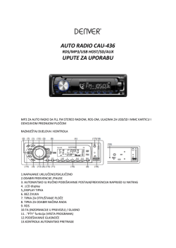
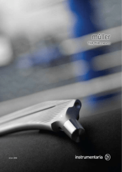
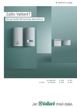
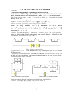
OTPORNIK ZA UZEMLJENJE
NULTOČKE TRANSFORMATORA
NEUTRAL EARTHING RESISTOR
TIP / TYPE
74003
OUN
2
OUN - Otpornik za uzemljenje 0-točke
transformatora
Otpornici za uzemljenje 0- točke upotrebljavaju se u
distributivnim mrežama izmjenične struje za ograničenje
struje greške koja teče od zvjezdišta transformatora u slučaju
dozemnog spoja u sistemu. Nazivna vrijednost se odabire
tako da struju greške ograniči na vrijednost potrebnu za proradu
zaštitnih releja u traženom vremenskom periodu
(obično 5, 10 ili 30 s).
Neutral earthing resistor
Neutral earthing resistor are used in AC distribution
networks for limiting the earth fault current which flows
from the transformer neutral point. The rated value is
selected with a view to limiting the fault current to the
protective relay actuation value within the required time
period (usually 5, 10, or 30 s).
Sl. 1 / Fig. 1
Otpornik tip OUN / Resistor type OUN
3
Nazivne vrijednosti
Otpornici za uzemljenje 0 - točke imaju sljedeće nazivne
vrijednosti :
a) Nazivni napon
Un
b) Nazivna struja
In
c) Nazivno vrijeme tn
d) Nazivni otpor
±10% deklarirane vrijednosti kod 20 °C
U standardnoj izvedbi izrađujemo otpornike za fazni napon
mreže od 6, 12, 18, 21 kV, za struje 150, 300, 700, 1000 A i
vrijeme 5, 10, 30 s.
Rated values
Neutral earthing resistor have the following rated values:
a) Rated voltage Un
b) Rated current In
c) Rated time
tn
d) Rated resistance ±10% the declared value at 20 °C
We manufacture standard resistors for network
phase - to - ground voltages of 6, 12, 18, 21 kV,
currents 150, 300, 700, 1000 A and times 5, 10, 30 s.
Aktivni dio i kućište
Active part and enclosure
Aktivni dio izrađen je od nerđajučeg čelika
(x10 CrNiTi 18,9 prema DIN17440) i postavljen na potporne
porculanske izolatore (IEC 60273). Otporni elementi od kojih su
izrađeni otpornici podnose nadtemperaturu od 760 °C prema
(ANSI/IEEE 32). Na standardnim otpornicima provedena su
visokonaponska ispitivanja prema IEC 60071-1.
Kućište je izrađeno u modularnom sistemu tako da omogućava
"rastezljivost" volumena u ovisnosti o veličini aktivnog dijela.
Otvaranjem vrata, koja se nalaze sa svih strana kućišta, moguć je
pristup bilo kojem dijelu radi održavanja. Otpornik može imati
"n" jediničnih modula, ovisno o nazivnim vrijednostima, koji se
međusobno spajaju u transportne cjeline (maksimalno 5 modula).
Na mjestu ugradnje transportne cjeline se spajaju u jedinstveno
kućište.
The active part is made of stainless steel
(x10 CrNiTi 18,9 to DIN17440) and mounted on porcelain
insulators IEC 60273. The resistors elements endured
temperature rise of 760 °C (ANSI/IEEE 32).
High voltage test according to IEC 60071-1 is performed on
standard resistors.
The enclosure is of a modular design granting the volume
"flexibility" depending on the size of the active part.
The access to any component part, for the repair and
maintance purposes, is possible through the doors provided
on all sides of the enclosure. A resistor may have an "n"
number of modules, depending on the calculation data,
which are interconnected in the shipping assemblies
(up to 5 modules each). At the installation site, the shipping
assemblies are fitted into a single housing.
Sl. 2 / Fig. 2
3 modula / 3 modules
4
Sl. 3 / Fig. 3
1 modul / 1 module
Spajanje
Connection
Priključak 0-točke transformatora izvodi se na visokonaponski
provodni izolator (12 kV ili 24 kV) koji je smješten na
spojnoj kutiji (sl. 4). Skidanjem poklopca spojne kutije moguć
je pristup strujnom transformatoru i stezaljkama za njegovo
spajanje. Priključak uzemljenja otpornika izvodi se preko
niskonaponskog provodnog izolatora smještenog na donjem
dijelu otpornika.
Na poseban zahtjev izrađujemo i otpornike s kabelskim ulazom
(sl. 5).
The transformer neutral point is connected to the high-voltage
bushing (12 kV or 24 kV) fitted on the terminal box (Fig. 4).
The access to the current transformer and corresponding
terminals is possible when the terminal box cover is removed.
The resistor earthing is connected through the low-voltage
bushing installed the resistor bottom.
On special request we made the resistors with cable entry
(Fig. 5).
Sl. 4 / Fig. 4
Shema otpornika /
Scheme of resistor
Sl. 5 / Fig. 5
Shema otpornika /
Sheme of resistor
Protection
Zaštita
Standardno kućište izrađeno je u stupnju mehaničke zaštite
IP23 (IEC 60529). Isporučujemo i otpornike za unutarnju
montažu bez zaštite od dodira i vode (IP00). Ugradnja takvog
otpornika predviđena je u posebnu zatvorenu prostoriju u
koju nitko ne ulazi dok je otpornik pod naponom. Ukoliko
se ugrađuje u jednu veću prostoriju zajedno s ostalom
opremom tada je predviđeno da se dio prostorije pregradi
zaštitnom mrežom.
A standard enclosure is designed with mechanical protection
IP23 (IEC 60529). Also we made the resistors for indoor
installation without mechanical protection (IP00). Such resistor
are designed for installation within a separate closed room
where nobody can enter while the resistor is under voltage.
Where the resistor is installed in a larger room, together with
other equipment, that particular part of the room shall be
separated by a protective grid.
Sl. 7 / Fig. 7
IP23- bojano / painted
Sl. 6 / Fig. 6
IP23 - Vruće cinčano /
Hot-dip galvanazed
Sl. 8 / Fig. 8
IP00
Sl. 9 / Fig. 9
Visokonaponsko ispitivanje /
High voltage test
5
Mjerne Skice / Outline drawings
Tablica broja modula (n) standardnih izvedbi
Table of number (n) standard modules
18 kV
21 kV
2
1
2
3
30 s
1
2
4
4
2
5
*
3
4
5
3
5
*
Ulazni priključak
Incoming terminal
*
*
*
*
*
*
*
*
800
900
min 2200
12 kV
150 A
300 A
700 A
1000 A
150 A
300 A
700 A
1000 A
300 A
700 A
1000 A
300 A
700 A
1000 A
10 s
1
1
2
2030
6 kV
5s
1
1
1
1
1
1
2
2
1
3
3
2
4
4
1040
100
n
OSNOVNI MODUL
BASIC MODULE
1740
360
Æ17
Izlazni priključak
Outgoing terminal
* Mjerne skice na upit
* Outline drawings on special request
Ulazni priključak
Incoming terminal
1040
a
Izlazni priključak
860 x n
Outgoing terminal
"n" MODULA
"n" MODULES
1040
PLAN SIDRENJA OD 1 DO 5 MODULA
FLOOR FIXING FROM 1 TO 5 MODULES
"n"
a
a
Sidrenje se vrši sidrenim vijcima M16
Floor fixing is provided with M16 anchor bolts
6
1
800
2
1660
3
2520
4
3380
5
4240
Otporni element (osnovni podaci) / Resistance element (basic data)
- Matrijal / Material : X10 CrNiTi 18.9 (DIN 17440)
- Temperaturni koeficijent / Temperature Coefficient: a=0,001/K
- Specifični otpor / Resistivity: 73mWcm
- Specifični toplinski koeficijent / Specific heat: c=500J/kgK
Apsorbirana energija otpornika / Energy absorbed by resistor
2
W=R·I ·t
R·I2·t
DT= m·c·n
W(J)=Q(J)
Q=c·m·DT
- toplinska energija / thermal energy
- električna energija / electrical energy
- efektivna vrijednost struje / effective current
- masa pojedinog elementa / mass of each element
- otpor elementa / resistance of element
- vrijeme ograničenja struje / current limiting time
- (Q2-Q1) razlika temperature (početak i kraj opterečenja) /
temperature rise after rated time
c (J/kgK) - specifični toplinski koeficijent / spec. heat of the material
- broj otpornih elemenata / number of lelments
n
Q (J)
W (J)
I (A)
m (kg)
R (W)
t (s)
DT (K)
Proračun električnog otpora pri različitim temperaturama /
Calculation of electrical rezistance at different temperature
R02=R01·[1+a·(T01-Tamb)]
a - temperaturni koeficijent / temperature coefficient
R02 - otpor (W) na kraju opterećenja / resistor (W) after rated time
R01 - otpor (W) na početku opterećenja / resistor (W) at different temperatures
Tamb - temperatura okoline (oC) / ambient temperature (oC)
o
o
T01 - temperatura otpornika na kraju opterećenja ( C) / temperature of resistor after rated time ( C)
Podaci za narudžbu / Ordering Particulars
Nazivni napon
Rated Voltage
Nazivna struja
Rated Current
Nazivno vrijeme
Rated Time
Otpor
Resistance
Stupanj mehaničke zaštite
Deegre of Mechanical Protection
Un =
In=
kV
t =
R =
s
W
IP
fazni napon
phase to ground voltage
A
vrijeme ograničenja struje
current limiting time
± 10 % deklarirane vrijednosti kod 20 °C
± 10 % of the declared value at 20 °C
IP00 ili IP23
IP00 or IP23
* Ukoliko je potrebna ugradnja strujnih transformatora potrebno ih je u potpunosti definirati. Predviđena je ugradnja
transformatora proizvodnje "KONČAR".
* Na poseban zahtjev u kućište otpornika ugrađujemo grijače upravljane higrostatom. Pomoćni napon: 230 V, 50 Hz.
* In case the installation of current transformers is required, they shall be defined in full detail. The unit designed for the
installation of "KONČAR" transformers.
* At request, hygrostat controlled heaters may be installed in the resistor enclosure. Auxiliary voltage supply: 230 V, 50 Hz.
7
Standardano kućište - Stupanj mehaničke zaštite IP23 (IEC 60529)
Standard Enclosure - Deegre of Mechanical Protection IP23 (IEC 60529)
Vijak sa prstenastom
glavom za dizanje
kućišta M16
Lifting Eyebolts M16
Provodni porculanski
izolator za priključak
Bushing for Neutral
Connection
Kabelski ulaz
(na zahtjev)
Cable Entry
(Optional)
Strujni transformator
s rednim stezaljkama
(na zahtjev)
Current Transformer
with Block Terminals
(Optional)
Vrata Doors
Potporni porculanski
izolatori
Porcelain Post
Insulators
Higrostat (na zahtjev)
Hygrostat (Optional)
Otporni elementi od
nerđajučeg čelika
Stainless Steel
Resistor Elements
Grijači (na zahtjev)
Heather (Optional)
Izlazni priključak M12
Outgoing M12 Terminal
Natpisna pločica
Name Plate
Tip: OUN
IP
Br.
Rp.
Un.
kV In.
Rn.
W t
Made in Croatia
A
s
Strujni obuhvatni
transformator
(na zahtjev)
Ring - type Current
Transformer
(Optional)
Pridržavamo pravo promjene podataka. Ostale podatke dajemo na upit.
We keep the right to change the data. Other data are given on request.
II 12 10
74003(1,2)
© Copyright 2026 Paperzz