Manuale per il collegamento e l’uso - Installation and operation manual
Manuel pour le raccordement et l’emploi - Installations - und Benutzerhandbuch
Manual para el conexionado y el uso - Manual de instalação e utilização
ǼȖȤİȚȡȓįȚȠıȪȞįİıȘȢțĮȚȤȡȒıȘȢ
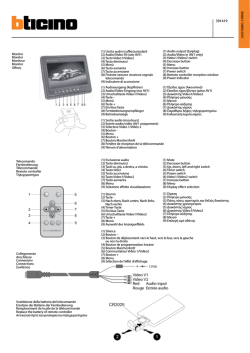
ISTRUZIONI PER IL MONTAGGIO DELLE TARGHE CITOFONICHE/VIDEOCITOFONICHE SERIE 1300
INSTRUCTIONS FOR THE ASSEMBLING OF AUDIO/VIDEO ENTRANCE PANELS SERIES 1300
INSTRUCTIONS POUR LE MONTAGE DES PLAQUES DE RUE AUDIO/VIDÉO SÉRIE 1300
ANLEITUNG FÜR DEN EINBAU DER AUDIO-/VIDEO-KLINGELTABLEAUS SERIE 1300
INSTRUCCIONES PARA EL MONTAJE DE LAS PLACAS AUDIO/VÍDEO SERIE 1300
INSTRUÇÕES PARA A MONTAGEM DAS BOTONEIRAS ÁUDIO/VÍDEO SÉRIE 1300
ȅǻǾīǿǼȈȉȅȆȅĬǼȉǾȈǾȈȂȆȅȊȉȅȃǿǼȇȍȃĬȊȇȅȉǾȁǼĭȍȃȅȊĬȊȇȅȉǾȁǼȅȇǹȈǾȈȈǼǿȇǹȈ
1300
1300
CARATTERISTICHE TECNICHE DELLE TARGHE SERIE 1300
Placca in estruso di alluminio di spessore 18/10.
Grado di protezione IP44
Testate in tecnopolimero antiurto, resistente ai raggi UV.
Supporto per i tasti in policarbonato antiurto trasparente.
Telaio in un unico blocco stampato in lamiera 12/10 preverniciata bianca.
Tasti in policarbonato trasparente ricoperti con una protezione in acciaio inox
Gli elementi della serie 1300 permettono la composizione di targhe per impianti
citofonici e videocitofonici con tecnologia:
- Due Fili Elvox
- Digibus
- Chiamata Sound System o c.a.
Le targhe sono fornite di placca frontale e telaio e sono da completare con l’elettronica
e relativi componenti aggiuntivi forniti separatamente da scegliere in funzione del tipo di
impianto (Due Fili Elvox, Digibus, Sound System, chiamata c.a.) e il tipo di installazione.
L’istruzione si riferisce al solo montaggio della targa.
Per l’intallazione completa, il collegamento e la programmazione (per targhe elettroniche),
fare riferimento al manuale dell’unità elettronica, telecamera o posto esterno da inserire:
Per sistema DUE FILI:
Unità elettronica a pulsanti: 13F3 (audio), 13F5 (video)
Unità elettronica con tastiera alfanumerica: 13F4 (audio), 13F7 (video)
Posto esterno audio: 6931.
Per sistema DIGIBUS:
Unità elettronica a pulsanti: 1283 (audio), 1285 (video)
Unità elettronica con tastiera alfanumerica: 1282 (audio), 1286 (video)
Per sistema Sound System o C.A.:
Posti esterni audio: Art. 930A, 930C, 930D, 930F, 930G.
Telecamera con Posto esterno: Art. 559A, 559B, 560A.
Componenti aggiuntivi per impianti Due Fili e Digibus
La targa viene fornita con la predisposizione per impianti videocitofonici, è da implementare
con i seguenti articoli:
Scatola da incasso parete art. 9192 per targhe in 2 moduli verticali oppure art. 9193
per targhe in 3 moduli verticali.
Nota: Le scatole 9192 o 9193 non possono essere combinate tra loro ma solo tra: 9192
con 9192 oppure 9193 con 9193.
Cornici parapioggia art. C321, C322, C323, C324 per targhe su 2 moduli verticali
oppure C331, C332, C333, C334 per targhe su 3 moduli verticali
Scatole da esterno con parapioggia art. S321, S322, S323, S324 per taghe in 2 moduli
verticali oppure S331, S332, S333, S334 per targhe in 3 moduli verticali.
Tasto esterno art. R131, per aumentare i tasti di chiamata delle placche art. 1321, 1331
oppure modulo copriforo per tasto esterno art. R130 per diminuire i tasti di chiamata
delle placche art. 1358, 1372.
Unità elettronica audio a pulsanti Art. 13F3 (Due Fili) o Art. 1283 (Digibus)
Unità elettronica audio alfanumerica Art. 13F4 (Due Fili) o Art. 1882 (Digibus)
Unità elettronica video a pulsanti Art. 13F5 (Due Fili) o Art. 1285 (Digibus)
Unità elettronica video alfanumerica Art. 13F7 (Due Fili) o Art. 1286 (Digibus)
Modulo supplementere con 4 pulsanti per targhe elettroniche Due Fili Elvox e Digibus,
Art. 12TS (fornito separatamente)
E’ possibile predisporre la medesima targa per unità elettronica audio in questo caso si
deve togliere l’anello dal retro della placca frontale, evidenziato con numero 1 in figura 6,
inserire al suo posto la mascherina di chiusura obiettivo, evidenziata con numero 2 di figura
6, sul telaio (B).
Componenti aggiuntivi per impianti con chiamata Sound System o in c.a.
La targa viene fornita con la predisposizione per impianti videocitofonici, è da implementare
con i seguenti articoli:
Scatola da incasso parete art. 9192 per targhe in 2 moduli verticali oppure art. 9193
per targhe in 3 moduli verticali.
Nota: Le scatole 9192 o 9193 non possono essere combinate tra loro ma solo tra:
9192 con 9192 oppure 9193 con 9193.
Telecamera con posto esterno art. 559A o 559B o 560A o posto esterno Art. 930A,
930B, 930C, 930D, 930F o Art. 930G (la figura 1 illustra come inserire la telecamera
sul telaio)
Pulsanti art. R200 o R200/50 (R200/50 = confezione con 50 pulsanti R200)
Tasto esterno art. R131, per aumentare i tasti di chiamata delle placche art. 1321,
1331 oppure modulo copriforo per tasto esterno art. R130 per diminuire i tasti di
chiamata delle placche art. 1358, 1372.
LED per illuminazione cartellini portanomi art. R260
Diodi art. 0002/994 (per impianti “unifilari 1+N” o senza cavo coassiale).
Cornici parapioggia art. C321, C322, C323, C324 per targhe su 2 moduli verticali
oppure C331, C332, C333, C334 per targhe su 3 moduli verticali
Scatole da esterno con parapioggia art. S321, S322, S323, S324 per taghe in 2 moduli
verticali oppure S331, S332, S333, S334 per targhe in 3 moduli verticali.
E’ possibile predisporre la medesima targa per il solo posto esterno audio in questo caso
si deve togliere l’anello dal retro della placca frontale, evidenziato con numero 1 in figura
6, inserire al suo posto la mascherina di chiusura obiettivo, evidenziata con numero 2 di
figura 6, sul telaio (B), installare con le viti in dotazione la staffetta (C) per posto esterno
audio, (vedi figura 20, 22, 24).
2
TECHNICAL FEATURES OF 1300 SERIES ENTRANCE PANELS
Plate in 18/10 gauge extruded aluminium.
Protection class: IP44
End sections made of UV and impact resistant technopolymer.
Support for transparent shockproof polycarbonate buttons
Frame made from a single moulded piece of 12/10 gauge aluminium sheet, prepainted white.
Transparent polycarbonate buttons covered with stainless steel protection
The items in the 1300 series enable making entrance panels for audio and video door
entry systems with the technology of:
- Elvox Due Fili
- Digibus
- Sound System or C.A. call
The entrance panels are supplied with a front plate and a frame and are comprehensive
of electronics and related add-ons supplied separately to be selected depending on the
type of plant (Elvox Due Fili, Digibus, Sound System, c.a. call) and the type of installation.
The instructions refer to mounting the entrance panel only.
For complete installation, connection and programming (for electronic panels), please refer
to the manual of the electronic unit, camera or speech unit to be added:
For the DUE FILI system:
Push-button electronic unit: 13F3 (audio), 13F5 (video)
Electronic unit with alphanumeric keypad: 13F4 (audio), 13F7 (video)
Audio speech unit: 6931.
For the DIGIBUS system:
Push-button electronic unit: 1283 (audio), 1285 (video)
Electronic unit with alphanumeric keypad: 1282 (audio), 1286 (video)
For the Sound System or C.A. system:
Audio speech units: Art. 930A, 930C, 930D, 930F, 930G.
Camera with Speech Unit: Art. 559A, 559B, 560A.
Additional components for Due Fili and Digibus systems
The entrance panel is supplied ready for video door entry systems and is to be implemented
with the following items:
Flush-mounted back box art. 9192 for entrance panels in 2 vertical modules or art. 9193
for entrance panels in 3 vertical modules.
Note: Back boxes 9192 and 9193 cannot be matched with each other but only as
follows: 9192 with 9192 or 9193 with 9193.
Rainproof covers art. C321, C322, C323, C324 for entrance panels in 2 vertical
modules or C331, C332, C333, C334 for entrance panels in 3 vertical modules
Surface-mounted boxes with rainproof cover art. S321, S322, S323, S324 for entrance
panels in 2 vertical modules or S331, S332, S333, S334 for entrance panels in 3
vertical modules.
External key art. R131 for increasing the number of call keys on plates art. 1321, 1331
or blanking module for external key art. R130 for reducing the number of call keys on
plates art. 1358, 1372.
Push-button audio electronic unit Art. 13F3 (Due Fili) or Art. 1283 (Digibus)
Alphanumeric audio electronic unit Art. 13F4 (Due Fili) or Art. 1882 (Digibus)
Push-button video electronic unit Art. 13F5 (Due Fili) or Art. 1285 (Digibus)
Alphanumeric video electronic unit Art. 13F7 (Due Fili) or Art. 1286 (Digibus)
Supplementary module with 4 push-buttons for Elvox Due Fili and Digibus electronic
entrance panels, Art. 12TS (supplied separately)
The same entrance panel can be preset for the audio electronic unit, in which case you
need to remove the ring from the back of the front plate, marked with number 1 in figure 6,
and in its place insert the cover for closing the lens, marked with number 2 in figure 6, on
the frame (B).
Additional components for Sound System and C.A. call systems:
The entrance panel is preset for video entrance panel systems and is to be implemented
with the following articles:
Flush-mounted back box type 9192 for entrance panels in 2 vertical modules or type
9193 for entrance panels in 3 vertical modules.
Note: Back boxes type 9192 or 9193 cannot be matched between them but only
between: 9192 with 9192 or 9193 with 9193
Video camera with speech unit type 559A or 559B or 560A or speech unit type 930A,
930B, 930C, 930D, 930F or Art. 930G (fig. 1 shows how to insert the camera in the
frame).
Push-buttons type R200, R200/50 (R200/50 = package with 50 push-buttons R200)
External key type R131 for increasing the number of call keys on plates type 1321,
1331 or blanking module for external key type R130 for reducing the number of call
keys on plates type 1358, 1372.
LED for lighting name-tags type R260
Diodes type 0002/994 (for “1+N wires” or without coaxial cable).
Rainproof covers type C321, C322, C323, C324 for entrance panels in 2 vertical
modules or C331, C332, C333, C334 for entrance panels in 3 vertical modules
Surface-mounted boxes with rainproof cover type S321, S322, S323, S324 for
entrance panels in 2 vertical modules or S331, S332, S333, S334 for entrance panels
in 3 vertical modules.
The same entrance panel can be preset for the sole external speech unit; in this case
remove the ring from the back of the front plate (identified with number 1 in fig. 6); insert
in its place the cover for closing the lens (shown with number 2 in fig. 6) in the frame “B”,
install the bracket “C” (using the screws supplied) for the speech unit (see fig. 20, 22, 24).
IT
EN
1300
CARACTÉRISTIQUES TECHNIQUES DES PLAQUES SÉRIE 1300
Plaque en extrudé d’aluminium, épaisseur 18/10.
Degré de protection IP44
Chants en technopolymère antichoc, résistant aux rayons UV.
Support pour les touches en polycarbonate antichoc transparent
Châssis en un unique bloc embouti de tôle 12/10 pré-peinte blanche.
Touches en polycarbonate transparent recouvertes avec une protection en acier
inox.
Les éléments de la série 1300 permettent de composer des plaques pour circuits
portiers et portiers-vidéo avec technologie :
- Due Fili Elvox
- Digibus
- Appel Sound System ou c.a.
Les plaques sont dotées d’une platine frontale et d’un châssis et doivent être complétées
avec l’électronique et les composants supplémentaires correspondants fournis à part, à
choisir en fonction du type de circuit (Due Fili Elvox, Digibus, Sound System, appel c.a.)
et du type d’installation.
La consigne concerne uniquement le montage de la plaque.
Pour l’installation complète, la connexion et la programmation (pour plaques
électroniques), faire référence au manuel de l’unité électronique, de la caméra ou du
poste externe à insérer :
Pour système DUE FILI :
Unité électronique à boutons : 13F3 (audio), 13F5 (vidéo)
Unité électronique avec clavier alphanumérique : 13F4 (audio), 13F7 (vidéo)
Poste externe audio : 6931.
Pour système DIGIBUS :
Unité électronique à boutons : 1283 (audio), 1285 (vidéo)
Unité électronique avec clavier alphanumérique : 1282 (audio), 1286 (vidéo)
Pour système Sound System ou C.A. :
Postes externes audio : Art. 930A, 930C, 930D, 930F, 930G.
Caméra avec Poste externe : Art. 559A, 559B, 560A.
Composants supplémentaires pour circuits Due Fili et Digibus
La plaque est conçue pour accepter l’installation de circuits portiers-vidéo et être complétée
avec les articles suivants :
Boîte d’encastrement murale art. 9192 pour plaques en 2 modules verticaux ou art.
9193 pour plaques en 3 modules verticaux.
Remarque : Les boîtes 9192 ou 9193 ne peuvent pas être accouplées entre elles mais
uniquement de la façon suivante : 9192 avec 9192 ou 9193 avec 9193.
Cadres anti-pluie art. C321, C322, C323, C324 pour plaques sur 2 modules verticaux
ou C331, C332, C333, C334 pour plaques sur 3 modules verticaux
Boîtes extérieures avec anti-pluie art. S321, S322, S323, S324 pour plaques en 2
modules verticaux ou S331, S332, S333, S334 pour plaques en 3 modules verticaux.
Touche extérieure art. R131 pour augmenter les touches d’appel des plaques art.
1321, 1331 ou module cache-trou pour touche extérieure art. R130 pour diminuer les
touches d’appel des plaques art. 1358, 1372.
Unité électronique audio à boutons Art. 13F3 (Due Fili) ou Art. 1283 (Digibus)
Unité électronique audio alphanumérique Art. 13F4 (Due Fili) ou Art. 1882 (Digibus)
Unité électronique vidéo à boutons Art. 13F5 (Due Fili) ou Art. 1285 (Digibus)
Unité électronique vidéo alphanumérique Art. 13F7 (Due Fili) ou Art. 1286 (Digibus)
Module supplémentaire avec 4 boutons pour plaques électroniques Due Fili Elvox et
Digibus, Art. 12TS (fourni à part)
Possibilité de prédisposer la même plaque pour une unité électronique audio ; dans ce cas,
ôter l’anneau portant le numéro 1 figure 6, par l’arrière de la plaque frontale, le remplacer
par le cache fermant l’objectif et portant le numéro 2 figure 6, sur le châssis (B).
TECHNISCHE MERKMALE DER KLINGELTABLEAUS SERIE 1300
Platte aus stranggepresstem Aluminium mit 18/10 Stärke.
Schutzart IP44
Endstücke aus stoß- und UV-festem Technopolymer.
Tastenhalterung aus stoßfestem durchsichtigem Polycarbonat
Rahmen aus gepresstem Aluminiumblech mit 12/10 Stärke, in weiß vorlackiert.
Tasten aus durchsichtigem Polycarbonat mit Schutzüberzug aus Edelstahl.
Die Elemente der Serie 1300 ermöglichen die Zusammenstellung von Klingeltableaus
für Türsprech- und Video-Türsprechanlagen mit Technologie:
- Due Fili Elvox
- Digibus
- Sound System oder Wechselstromruf
Die Klingeltableaus sind mit Frontplatte und Trägerrahmen versehen und müssen mit
der Elektronik und den entsprechenden zusätzlichen Komponenten ergänzt werden, die
separat geliefert werden und je nach Anlage (Due Fili Elvox, Digibus, Sound System,
Wechselstromruf) und Installationsart zu wählen sind.
Die Anleitung bezieht sich nur auf die Montage des Klingeltableaus.
Für die vollständige Installation, den Anschluss und die Programmierung (elektronische
Klingeltableaus) wird auf das Handbuch der zu installierenden Elektronikeinheit, Kamera
oder Außensprechstelle verwiesen:
Für System DUE FILI:
Elektronikeinheit mit Tasten: 13F3 (Audio), 13F5 (Video)
Elektronikeinheit mit alphanumerischer Tastatur: 13F4 (Audio), 13F7 (Video)
Außensprechstelle: 6931.
Für System DIGIBUS:
Elektronikeinheit mit Tasten: 1283 (Audio), 1285 (Video)
Elektronikeinheit mit alphanumerischer Tastatur: 1282 (Audio), 1286 (Video)
Für System Sound System oder Wechselstromruf:
Außensprechstellen: Art. 930A, 930C, 930D, 930F, 930G.
Kamera mit Außensprechstelle: Art. 559A, 559B, 560A.
Zusatzkomponenten für Anlagen Due Fili und Digibus
Das Klingeltableau wird mit Auslegung für Videosprechanlagen geliefert und muss mit den
folgenden Artikeln ergänzt werden:
Unterputzgehäuse Art. 9192 für Klingeltableaus in 2 vertikalen Modulen oder Art. 9193
für Klingeltableaus in 3 vertikalen Modulen.
Hinweis: Die Gehäuse 9192 oder 9193 können nicht miteinander kombiniert werden,
sondern nur: 9192 mit 9192 oder 9193 mit 9193.
Regenschutzrahmen Art. C321, C322, C323, C324 für Klingeltableaus in 2 vertikalen
Modulen oder C331, C332, C333, C334 für Klingeltableaus in 3 vertikalen Modulen
Aufputzgehäuse mit Regenschutz Art. S321, S322, S323, S324 für Klingeltableaus in
2 vertikalen Modulen oder S331, S332, S333, S334 für Klingeltableaus in 3 vertikalen
Modulen.
Außentaste Art. R131, zur Erhöhung der Ruftastenanzahl der Frontplatten Art.
1321, 1331 oder Putzabdeckrahmen für Außentaste Art. R130 zur Verringerung der
Ruftastenanzahl der Frontplatten Art. 1358, 1372.
Audio-Elektronikeinheit mit Tasten Art. 13F3 (Due Fili) oder Art. 1283 (Digibus)
Audio-Elektronikeinheit mit alphanumerischer Tastatur Art. 13F4 (Due Fili) oder Art.
1882 (Digibus)
Video-Elektronikeinheit mit Tasten Art. 13F5 (Due Fili) oder Art. 1285 (Digibus)
Video-Elektronikeinheit mit alphanumerischer Tastatur Art. 13F7 (Due Fili) oder Art.
1286 (Digibus)
Zusatzmodul mit 4 Tasten für elektronische Klingeltableaus Due Fili Elvox und Digibus,
Art. 12TS (separat geliefert)
Dasselbe Klingeltableau kann für die Audio-Elektronikeinheit ausgelegt werden. In diesem
Fall den auf Abbildung 6 mit Nr. 1 gekennzeichneten Ring an der Rückseite der Frontplatte
entfernen und an seiner Stelle die auf Abbildung 6 mit Nr. 2 gekennzeichnete ObjektivAbdeckblende am Rahmen einsetzen (B).
Composants complémentaires pour installations avec appel Sound
System ou en c.a.
La plaque de rue est fournie avec la prédisposition pour installation vidéo et doit être
utilisée avec les articles suivants :
Boîtier à encastrer art. 9192 pour plaques en 2 modules verticaux ou bien art. 9193
pour plaques en 3 modules verticaux.
Remarque : les boîtiers 9192 ou 9193 ne peuvent pas être asssemblé entre eux. On
ne peut assembler que le 9192 avec le 9192 ou bien le 9193 avec le 9193.
Caméra avec poste externe art. 559A ou 559B ou 560A ou poste externe art. 930A,
930B, 930C, 930D, 930F ou art. 930G (la figure 1 indique comment insérer la caméra
sur le châssis).
Boutons art. R200 ou R200/50 (R200/50 = emballage avec 50 boutons R200)
Touche externe art. R131, pour augmenter les touches d’appel des plaques art. 1321,
1331 ou bien module cache-trou pour touche externe art. R130 pour diminuer les
touches d’appel des plaques art. 1358, 1372.
LED pour éclairage étiquettes porte-noms art. R260
Diodes art. 0002/994 (pour installations « unifilaires 1 + N » ou sans câble coaxial.
Cadres anti-pluie art. C321, C322, C323, C324 pour plaques en 2 modules verticaux
ou bien C331, C332, C333, C334 pour plaques en 3 modules verticaux.
Boîtiers pour montage en saillie avec protection contre la pluie art. S321, S322, S323,
S324 pour plaques en 2 modules verticaux ou bien S331, S332, S333, S334 pour
plaques en 3 modules verticaux.
Il est aussi possible de prédisposer la même plaque de rue pour un seul poste externe
audio ; dans ce cas, ôter l’anneau portant le numéro 1 figure 6 par l’arrière de la plaque
frontale, le remplacer par le cache fermant l’objectif et portant le numéro 2 figure 6, sur
le châssis (B), installer l’étrier (C) avec les vis fournies pour le poste externe audio (voir
figures 20, 22, 24).
FR
DE
Zusatzkomponenten für Anlagen mit Sound-System- oder Wechselstromruf
Das Klingeltableau ist vorbereitet für Video-Türsprechanlagen und wird mit folgenden
Artikeln eingesetzt:
Unterputzgehäuse Art. 9192 für Klingeltableaus mit 2 vertikalen Modulen oder Art.
9193 für Klingeltableaus mit 3 vertikalen Modulen.
Hinweis: Die Gehäuse 9192 bzw. 9193 können nicht miteinander kombiniert werden,
sondern nur wie folgt: 9192 mit 9192 oder 9193 mit 9193.
Kamera mit Sprechstelle Art. 559A, 559B oder 560A oder Sprechstelle Art. 930A,
930B, 930C, 930D, 930F oder 930G (die Abb. 1 stellt dar, wie die Kamera in den
Rahmen eingesetzt wird).
Tasten Art. R200, R200/50 (R200/50 = Packung mit 50 Tasten R200)
Taste mit Namensschild Art. R131, zur Erhöhung der Ruftastenanzahl der Platten Art.
1321, 1331 oder Blindabdeckung für Taste mit Namensschild Art. R130 oder R130/10
zur Reduzierung der Ruftastenanzahl der Platten Art. 1358, 1372.
LED für Namensschildbeleuchtung Art. R260
Dioden Art. 0002/994 (für Anlagen mit „1+n“-Drahtsystem oder ohne Koaxialkabel)
Regenschutzrahmen Art. C321, C322, C323, C324 für Klingeltableaus mit 2 vertikalen
Modulen oder C331, C332, C333, C334 für Klingeltableaus mit 3 vertikalen Modulen.
Aufputzgehäuse mit Regenschutz Art. S321, S322, S323, S324 für Klingeltableaus mit
2 vertikalen Modulen oder S331, S332, S333, S334 für Klingeltableaus mit 3 vertikalen
Modulen.
Dasselbe Klingeltableau kann nur für die Sprechstelle vorbereitet werden; in diesen Fall
den Ring (der mit E in Abb. 6 bezeichnet ist) von der Frontblende abnehmen, stattdessen
die Abdeckung für das Objektiv (die mit D in Abb. 6 bezeichnet ist) einsetzen, und in
den Rahmen (B) mit den mitgelieferten Schrauben die Halterung (C) für die Sprechstelle
befestigen (siehe Abb. 20, 22, 24).
3
1300
CARACTERÍSTICAS TÉCNICAS DE LAS PLACAS SERIE 1300
Placa de aluminio extruido de 18/10 de espesor.
Grado de protección IP 44
Cabezales de tecnopolímero antichoque, resistente a los rayos UV.
Soporte para las teclas en policarbonato transparente a prueba de golpes
Bastidor en un único bloque estampado en chapa 12/10 prepintada de blanco.
Teclas de policarbonato transparente con protección de acero inoxidable.
Los elementos de la serie 1300 permiten la composición de placas para instalaciones
de portero automático y videoportero con tecnología:
- Due Fili Elvox
- Digibus
- llamada Sound System o c.a.
Las placas cuentan con placa frontal y bastidor y se completan con la electrónica y los
correspondientes componentes adicionales que se suministran por separado y se eligen
según el tipo de instalación (Due Fili Elvox, Digibus, Sound System, llamada c.a.) y el tipo
de montaje.
Las instrucciones se refieren solo al montaje de la placa.
Para el montaje completo, la conexión y la programación (para placas electrónicas),
consulte el manual de la unidad electrónica, de la cámara o del aparato externo que se
desea conectar:
CARACTERÍSTICAS TÉCNICAS DAS BOTONEIRAS SÉRIE 1300
Placa em alumínio extrudido com 18/10 de espessura.
Grau de proteção IP44
Topos em tecnopolímero anti-choque, resistente aos raios UV.
Suporte para botões em policarbonado antiefracção transparente.
Caixilho num único bloco impresso em chapa 12/10 pré-pintada branca.
Botões em policarbonado transparente cobertos com uma proteção em aço
inoxidável.
Os elementos da série 1300 permitem a composição de botoneiras para sistemas
áudio e vídeo com tecnologia:
- Due Fili Elvox
- Digibus
- Chamada Sound System ou c.a.
As botoneiras são fornecidas com espelho frontal e caixilho e devem ser completadas
com a electrónica e respectivos componentes adicionais fornecidos separadamente, a
escolher em função do tipo de sistema (Due Fili Elvox, Digibus, Sound System, chamada
c.a.) e do tipo de instalação.
A instrução refere-se apenas à montagem da botoneira.
Para a instalação completa, a ligação e a programação (para botoneiras electrónicas),
consulte o manual da unidade electrónica, telecâmara ou posto esterno a inserir:
Para sistema DUE FILI:
Unidad electrónica con pulsadores: 13F3 (audio), 13F5 (vídeo)
Unidad electrónica con teclado alfanumérico: 13F4 (audio), 13F7 (vídeo)
Aparato externo audio: 6931.
Para sistema DUE FILI:
Unidade electrónica de botões: 13F3 (áudio), 13F5 (vídeo)
Unidade electrónica com teclado alfanumérico: 13F4 (áudio), 13F7 (vídeo)
Posto externo áudio: 6931.
Para sistema Digibus:
Unidad electrónica con pulsadores: 1283 (audio), 1285 (vídeo)
Unidad electrónica con teclado alfanumérico: 1282 (audio), 1286 (vídeo)
Para sistema DIGIBUS:
Unidade electrónica de botões: 1283 (áudio), 1285 (vídeo)
Unidade electrónica com teclado alfanumérico: 1282 (áudio), 1286 (vídeo)
Para sistema Sound System o C.A.:
Aparatos externos audio: Art. 930A, 930C, 930D, 930F, 930G.
Cámara con aparato externo: Art. 559A, 559B, 560A.
Para sistema Sound System ou C.A.:
Postos externos áudio: Art. 930A, 930C, 930D, 930F, 930G.
Telecâmara com posto externo: Art. 559A, 559B, 560A.
Componentes adicionales para instalaciones Due Fili y Digibus
La placa se suministra con la preinstalación para videoportero y se implementa con los
siguientes artículos:
Caja de empotrar Art. 9192 para placas de 2 módulos verticales o bien Art. 9193 para
placas de 3 módulos verticales.
Nota: Las cajas 9192 o 9193 no pueden acoplarse entre sí, sino solo entre: 9192 con
9192 o bien 9193 con 9193.
Marcos antilluvia Art. C321, C322, C323, C324 para placas de 2 módulos verticales o
bien C331, C332, C333, C334 para placas de 3 módulos verticales
Cajas de superficie con marco antilluvia Art. S321, S322, S323, S324 para placas
de 2 módulos verticales o bien S331, S332, S333, S334 para placas de 3 módulos
verticales.
Tecla externa Art. R131, para aumentar el número de teclas de llamada de las placas
Art. 1321, 1331 o bien módulo ciego para tecla externa Art. R130 para disminuir el
número de teclas de llamada de las placas Art. 1358, 1372.
Unidad electrónica audio con pulsadores Art. 13F3 (Due Fili) o Art. 1283 (Digibus)
Unidad electrónica audio alfanumérica Art. 13F4 (Due Fili) o Art. 1882 (Digibus)
Unidad electrónica vídeo con pulsadores Art. 13F5 (Due Fili) o Art. 1285 (Digibus)
Unidad electrónica vídeo alfanumérica Art. 13F7 (Due Fili) o Art. 1286 (Digibus)
Módulo adicional con 4 pulsadores para placas electrónicas Due Fili ELVOX y Digibus,
Art. 12TS (se suministra por separado)
Componentes adicionais para sistemas Due Fili e Digibus
A botoneira é fornecida predisposta para sistemas de vídeo e deve ser implementada com
os artigos seguintes:
Caixa de embeber na parede art. 9192 para botoneiras em 2 módulos verticais ou art.
9193 para botoneiras em 3 módulos verticais.
Nota: As caixas 9192 ou 9193 não podem ser combinadas entre si, mas apenas entre:
9192 com 9192 ou 9193 com 9193.
Aros anti-chuva art. C321, C322, C323, C324 para botoneiras em 2 módulos verticais
ou C331, C332, C333, C334 para botoneiras em 3 módulos verticais
Caixas de montagem saliente com protecção anti-chuva art. S321, S322, S323, S324
para botoneiras em 2 módulos verticais ou S331, S332, S333, S334 para botoneiras
em 3 módulos verticais.
Tecla externa art. R131, para aumentar as teclas de chamada dos espelhos art. 1321,
1331 ou módulo de tampa cega para tecla externa art. R130 para diminuir as teclas de
chamada dos espelhos art. 1358, 1372.
Unidade electrónica áudio de botões Art. 13F3 (Due Fili) ou Art. 1283 (Digibus)
Unidade electrónica áudio alfanumérica Art. 13F4 (Due Fili) ou Art. 1882 (Digibus)
Unidade electrónica vídeo de botões Art. 13F5 (Due Fili) ou Art. 1285 (Digibus)
Unidade electrónica vídeo alfanumérica Art. 13F7 (Due Fili) ou Art. 1286 (Digibus)
Módulo suplementar com 4 botões para botoneiras electrónicas Due Fili Elvox e
Digibus, Art. 12TS (fornecido em separado)
Es posible preparar la misma placa para unidad electrónica audio y en este caso hay que
retirar el anillo desde la parte trasera de la placa frontal, indicado con el número 1 en la
figura 6 e introducir en su lugar la tapa del objetivo, indicada con el número 2 en la figura
6, en el bastidor (B).
É possível predispor a mesma botoneira para a unidade electrónica áudio; neste caso,
deve-se retirar o anel da parte de trás do espelho frontal, evidenciado com o número 1 na
figura 6, e inserir no seu lugar a tampa de fecho da objectiva, evidenciada com o número
2 da figura 6, no caixilho (B).
Componentes adicionales para sistemas con llamada Sound System o en c.a.
La placa viene suministrada con predisposición para instalaciones de videoporteros y se
ha de implementar con los artículos siguientes:
Caja de empotrar art. 9192 para placas de 2 módulos verticales o art. 9193 para
placas de 3 módulos verticales.
Nota: Las cajas 9192 o 9193 no se pueden combinar entre sí, sino sólo: 9192 con
9192 o bien 9193 con 9193.
Cámara con aparato externo art. 559A o 559B o 560A o aparato externo Art. 930A,
930B, 930C, 930D, 930F o 930G (la figura 1 ilustra como insertar la cámara sobre el
bastidor).
Pulsadores art. R200 o R200/50 (R200/50 = embalaje con 50 pulsadores R200)
Tecla externa Art. R131, para aumentar las teclas de llamada de las placas Art. 1321,
1331 o bien módulo embellecedor para tecla externa Art. R130 para disminuir las
teclas de llamada de las placas Art. 1358, 1372.
LEDs para iluminación de las tarjetas portanombres art. R260
Diodos art. 0002/994 (para instalaciones “unifilares 1+N” o sin cable coaxial).
Marcos antilluvia art. C321, C322, C323, C324 para placas de 2 módulos verticales o
bien C331, C332, C333, C334 para placas de 3 módulos verticales.
Caja de superficie con marco antilluvia art. S321, S322, S323, S324 para placas
de 2 módulos verticales o bien S331, S332, S333, S334 para placas de 3 módulos
verticales.
Componentes adicionais para instalações com chamada Sound
System ou c.a.
A botoneira é fornecida predisposta para instalações vídeo e deve ser implementada com
os artigos seguintes:
Caixa de embeber Art. 9192 para botoneiras com 2 módulos verticais ou Art. 9193
para botoneiras com 3 módulos verticais.
Nota: As caixas 9192 ou 9193 não podem ser combinadas entre si mas apenas entre:
9192 com 9192 ou 9193 com 9193.
Telecâmara com posto externo Art. 559A, 559B, 560A ou posto externo Art. 930A,
930B, 930C, 930D, 930F ou Art. 930G (a figura 1 apresenta a inserção da telecâmara
no caixilho).
Botões Art. R200 ou R500/50 (R500/50 = conjunto com 50 botões R200).
Botão externo art. R131 ou R131/10, para aumentar os botões de chamada das
placas art. 1321, 1331 ou módulo de cobertura do orifício para botão externo art.
R130 ou R130/10 para diminuir os botões de chamada das placas art. 1358, 1372.
LED para iluminação dos cartões porta-nomes Art. R260.
Diodos Art. 0002/994 (para instalações “unifilares 1+N” ou sem cabo coaxial).
Aros anti-chuva Art. C321, C322, C323, C324 para botoneiras com 2 módulos
verticais ou C331, C332, C333, C334 para botoneiras com 3 módulos verticais.
Caixas de montagem saliente com proteção anti-chuva Art. S321, S322, S323, S324
para botoneiras com 2 módulos verticais ou S331, S332, S333, S334 para botoneiras
com 3 módulos verticais.
Es posible predisponer la misma placa para el solo aparato externo audio; en este caso
se debe quitar el anillo desde la parte posterior de la plancha frontal, evidenciado con el
número 1 en la figura 6; insertar en su lugar en el bastidor “B” la máscara de cierre del
objetivo (evidenciada con el número 2 de figura 6); instalar con los tornillos en dotación el
soporte (C) para aparato externo audio (ver figura 20, 22, 24).
4
A mesma botoneira pode ser predisposta só para o posto externo áudio, neste caso
deve-se retirar o anel da parte posterior da placa frontal, evidenciado com o número 1 da
Fig. 6; em vez dele inserir no caixilho a máscara de fecho da objectiva “B”, evidenciada
com o número 2 da Fig. 6; instalar com os parafusos fornecidos o suporte “C” para posto
externo áudio (conforme a Fig. 20, 22, 24
ES
PT
1300
ȉǼȋȃǿȀǹȋǹȇǹȀȉǾȇǿȈȉǿȀǹȂȆȅȊȉȅȃǿǼȇȍȃȈǼǿȇǹȈ
ȆȜĮȓıȚȠĮʌȩİȟȦșȘȝȑȞȠĮȜȠȣȝȓȞȚȠʌȐȤȠȣȢ
ǺĮșȝȩȢʌȡȠıIJĮıȓĮȢ,3
DZțȡĮĮʌȩIJİȤȞȠʌȠȜȣȝİȡȑȢȣȜȚțȩĮȞșİțIJȚțȩıIJȚȢțȡȠȪıİȚȢțĮȚıIJȚȢĮțIJȓȞİȢ89
ȊʌȠıIJȒȡȚȖȝĮ ȖȚĮ IJĮ ʌȜȒțIJȡĮ Įʌȩ įȚĮijĮȞȑȢ ʌȠȜȣțĮȡȕȠȞȚțȩ ȣȜȚțȩ ĮȞșİțIJȚțȩ ıIJȚȢ
țȡȠȪıİȚȢ
ȆȜĮȓıȚȠĮʌȩİȞȚĮȓȠȤȣIJȩȝʌȜȠțȜİȣțȒȢʌȡȠȕİȡȞȚțȦȝȑȞȘȢȜĮȝĮȡȓȞĮȢ
ȆȜȒțIJȡĮ Įʌȩ įȚĮijĮȞȑȢ ʌȠȜȣțĮȡȕȠȞȚțȩ ȣȜȚțȩ ȝİ İʌȚțȐȜȣȥȘ Įʌȩ ʌȡȠıIJĮIJİȣIJȚțȩ
ĮȞȠȟİȓįȦIJȠȤȐȜȣȕĮ
ȉĮıIJȠȚȤİȓĮIJȘȢıİȚȡȐȢʌĮȡȑȤȠȣȞIJȘįȣȞĮIJȩIJȘIJĮıȣȞįȣĮıȝȠȪȝʌȠȣIJȠȞȚȑȡȦȞȖȚĮ
İȖțĮIJĮıIJȐıİȚȢșȣȡȠIJȘȜȑijȦȞȠȣțĮȚșȣȡȠIJȘȜİȩȡĮıȘȢȝİIJİȤȞȠȜȠȖȓĮ
- Due Fili Elvox
- Digibus
ıȪıIJȘȝĮțȜȒıȘȢ6RXQG6\VWHPȒFD
ȅȚȝʌȠȣIJȠȞȚȑȡİȢįȚĮșȑIJȠȣȞȝʌȡȠıIJȚȞȒʌȜȐțĮțĮȚʌȜĮȓıȚȠțĮȚıȣȞįȣȐȗȠȞIJĮȚȝİȘȜİțIJȡȠȞȚțȐ
İȟĮȡIJȒȝĮIJĮțĮȚıȤİIJȚțȐʌȡȩıșİIJĮıIJȠȚȤİȓȠʌȠȣʌĮȡȑȤȠȞIJĮȚȟİȤȦȡȚıIJȐĮȞȐȜȠȖĮȝİIJȠȞIJȪʌȠ
IJȘȢİȖțĮIJȐıIJĮıȘȢDue Fili Elvox, Digibus, Sound6\VWHPıȪıIJȘȝĮțȜȒıȘȢFDțĮȚIJȠȞ
IJȡȩʌȠIJȠʌȠșȑIJȘıȘȢ
ȅȚȠįȘȖȓİȢĮȞĮijȑȡȠȞIJĮȚȝȩȞȠıIJȘȞIJȠʌȠșȑIJȘıȘIJȘȢȝʌȠȣIJȠȞȚȑȡĮȢ
īȚĮ ȠȜȩțȜȘȡȘ IJȘȞ İȖțĮIJȐıIJĮıȘ IJȘ ıȪȞįİıȘ țĮȚ IJȠȞ ʌȡȠȖȡĮȝȝĮIJȚıȝȩ ȖȚĮ ȘȜİțIJȡȠȞȚțȑȢ
ȝʌȠȣIJȠȞȚȑȡİȢ ĮȞĮIJȡȑȟIJİ ıIJȠ İȖȤİȚȡȓįȚȠ IJȘȢ ȘȜİțIJȡȠȞȚțȒȢ ȝȠȞȐįĮȢ IJȘȢ țȐȝİȡĮȢ Ȓ IJȠȣ
İȟȦIJİȡȚțȠȪıIJĮșȝȠȪȖȚĮIJȠʌȠșȑIJȘıȘ
īȚĮIJȠıȪıIJȘȝĮDUE FILI:
ǾȜİțIJȡȠȞȚțȒȝȠȞȐįĮȝİȝʌȠȣIJȩȞ)ȒȤȠȣ)İȚțȩȞĮȢ
ǾȜİțIJȡȠȞȚțȒȝȠȞȐįĮȝİĮȜijĮȡȚșȝȘIJȚțȩʌȜȘțIJȡȠȜȩȖȚȠ)ȒȤȠȣ)İȚțȩȞĮȢ
ǼȟȦIJİȡȚțȩȢıIJĮșȝȩȢȒȤȠȣ
īȚĮIJȠıȪıIJȘȝĮDIGIBUS:
ǾȜİțIJȡȠȞȚțȒȝȠȞȐįĮȝİȝʌȠȣIJȩȞȒȤȠȣİȚțȩȞĮȢ
ǾȜİțIJȡȠȞȚțȒȝȠȞȐįĮȝİĮȜijĮȡȚșȝȘIJȚțȩʌȜȘțIJȡȠȜȩȖȚȠȒȤȠȣİȚțȩȞĮȢ
īȚĮIJȠıȪıIJȘȝĮSound SystemȒC.A.:
ǼȟȦIJİȡȚțȠȓıIJĮșȝȠȓȒȤȠȣȀȦį$, 930C, 930D, 930F, 930G.
ȀȐȝİȡĮȝİİȟȦIJİȡȚțȩıIJĮșȝȩȀȦį. 559A, 559B, 560A.
ȆȡȩıșİIJĮİȟĮȡIJȒȝĮIJĮȖȚĮİȖțĮIJĮıIJȐıİȚȢ'XH)LOLțĮȚ'LJLEXV
ǾȝʌȠȣIJȠȞȚȑȡĮʌĮȡȑȤİIJĮȚȝİįȚĮȝȩȡijȦıȘȖȚĮİȖțĮIJĮıIJȐıİȚȢșȣȡȠIJȘȜİȩȡĮıȘȢțĮȚʌȡȑʌİȚȞĮ
ıȣȞįȣȐȗİIJĮȚȝİIJĮʌĮȡĮțȐIJȦʌȡȠȧȩȞIJĮ
ȋȦȞİȣIJȩİʌȚIJȠȓȤȚȠțȠȣIJȓțȦįȖȚĮȝʌȠȣIJȠȞȚȑȡİȢțĮIJĮțȩȡȣijȦȞȝȠȞȐįȦȞȒțȦį
ȖȚĮȝʌȠȣIJȠȞȚȑȡİȢțĮIJĮțȩȡȣijȦȞȝȠȞȐįȦȞ
ȈȘȝİȓȦıȘ ǻİȞ İȓȞĮȚ įȣȞĮIJȩȢ Ƞ ıȣȞįȣĮıȝȩȢ IJȦȞ țȠȣIJȚȫȞ Ȓ ʌĮȡȐ ȝȩȞȠ Ƞ
ıȣȞįȣĮıȝȩȢIJȠȣȝİIJȠȒIJȠȣȝİIJȠ
ȀȠȡȞȓȗİȢȖȚĮʌȡȠıIJĮıȓĮĮʌȩIJȘȕȡȠȤȒțȦį&&&&ȖȚĮȝʌȠȣIJȠȞȚȑȡİȢ
țĮIJĮțȩȡȣijȦȞȝȠȞȐįȦȞȒ&&&&ȖȚĮȝʌȠȣIJȠȞȚȑȡİȢțĮIJĮțȩȡȣijȦȞ
ȝȠȞȐįȦȞ
ǼȟȦIJİȡȚțȐ țȠȣIJȚȐ ȝİ ʌȡȠıIJĮIJİȣIJȚțȩ ȕȡȠȤȒȢ țȦį S321, S322, S323, S3 ȖȚĮ
ȝʌȠȣIJȠȞȚȑȡİȢțĮIJĮțȩȡȣijȦȞȝȠȞȐįȦȞȒ6666ȖȚĮȝʌȠȣIJȠȞȚȑȡİȢ
țĮIJĮțȩȡȣijȦȞȝȠȞȐįȦȞ
ǼȟȦIJİȡȚțȩ ʌȜȒțIJȡȠ țȦį 5 ȖȚĮ ĮȪȟȘıȘ IJȠȣ ĮȡȚșȝȠȪ IJȦȞ ʌȜȒțIJȡȦȞ țȜȒıȘȢ IJȦȞ
ʌȜĮțȫȞțȦįȒȝȠȞȐįĮțĮȜȪȝȝĮIJȠȢȖȚĮİȟȦIJİȡȚțȩʌȜȒțIJȡȠțȦį5ȖȚĮ
ȝİȓȦıȘIJȠȣĮȡȚșȝȠȪIJȦȞʌȜȒțIJȡȦȞțȜȒıȘȢIJȦȞʌȜĮțȫȞțȦį58, 1372.
ǾȜİțIJȡȠȞȚțȒȝȠȞȐįĮȒȤȠȣȝİȝʌȠȣIJȩȞțȦį)'XH)LOLȒțȦį(Digibus)
ǹȜijĮȡȚșȝȘIJȚțȒȘȜİțIJȡȠȞȚțȒȝȠȞȐįĮȒȤȠȣțȦį)'XH)LOLȒțȦį82 (Digibus)
ǾȜİțIJȡȠȞȚțȒȝȠȞȐįĮİȚțȩȞĮȢȝİȝʌȠȣIJȩȞțȦį)'XH)LOLȒțȦį 1285 (Digibus)
ǹȜijĮȡȚșȝȘIJȚțȒȘȜİțIJȡȠȞȚțȒȝȠȞȐįĮİȚțȩȞĮȢțȦį)'XH)LOLȒțȦį'LJLEXV)
ȈȣȝʌȜȘȡȦȝĮIJȚțȒȝȠȞȐįĮȝİȝʌȠȣIJȩȞȖȚĮȘȜİțIJȡȠȞȚțȑȢȝʌȠȣIJȠȞȚȑȡİȢ'XH)LOL(OYR[țĮȚ
'LJLEXVțȦį76ʌĮȡȑȤİIJĮȚȟİȤȦȡȚıIJȐ
ȂʌȠȡİȓIJİ ȞĮ įȚĮȝȠȡijȫıİIJİ IJȘȞ ȓįȚĮ ȝʌȠȣIJȠȞȚȑȡĮ ȖȚĮ IJȘȞ ȘȜİțIJȡȠȞȚțȒ ȝȠȞȐįĮ ȒȤȠȣ ȈIJȘȞ
ʌİȡȓʌIJȦıȘ ĮȣIJȒ ʌȡȑʌİȚ ȞĮ ĮijĮȚȡȑıİIJİ IJȠ įĮțIJȪȜȚȠ Įʌȩ IJȠ ʌȓıȦ ȝȑȡȠȢ IJȘȢ ȝʌȡȠıIJȚȞȒȢ
ʌȜȐțĮȢʌȠȣİʌȚıȘȝĮȓȞİIJĮȚȝİIJȠȞĮȡȚșȝȩıIJȘȞİȚțȩȞĮțĮȚȞĮIJȠʌȠșİIJȒıİIJİıIJȘșȑıȘ
IJȠȣIJȠțȐȜȣȝȝĮțȜİȚıȓȝĮIJȠȢijĮțȠȪʌȠȣİʌȚıȘȝĮȓȞİIJĮȚȝİIJȠȞĮȡȚșȝȩıIJȘȞİȚțȩȞĮıIJȠ
ʌȜĮȓıȚȠB).
ȆȡȩıșİIJĮİȟĮȡIJȒȝĮIJĮȖȚĮİȖțĮIJĮıIJȐıİȚȢȝİıȪıIJȘȝĮțȜȒıȘȢ6RXQG6\VWHPȒFD
ǾȝʌȠȣIJȠȞȚȑȡĮʌĮȡȑȤİIJĮȚȝİįȚĮȝȩȡijȦıȘȖȚĮİȖțĮIJĮıIJȐıİȚȢșȣȡȠIJȘȜİȩȡĮıȘȢțĮȚʌȡȑʌİȚȞĮ
ıȣȞįȣȐȗİIJĮȚȝİIJĮʌĮȡĮțȐIJȦʌȡȠȧȩȞIJĮ
ȋȦȞİȣIJȩİʌȚIJȠȓȤȚȠțȠȣIJȓțȦįȖȚĮȝʌȠȣIJȠȞȚȑȡİȢțĮIJĮțȩȡȣijȦȞȝȠȞȐįȦȞȒțȦį.
ȖȚĮȝʌȠȣIJȠȞȚȑȡİȢțĮIJĮțȩȡȣijȦȞȝȠȞȐįȦȞ
ȈȘȝİȓȦıȘǻİȞİȓȞĮȚįȣȞĮIJȩȢȠıȣȞįȣĮıȝȩȢIJȦȞțȠȣIJȚȫȞȒʌĮȡȐȝȩȞȠȠ
ıȣȞįȣĮıȝȩȢIJȠȣȝİIJȠȒIJȠȣȝİIJȠ
ȀȐȝİȡĮȝİİȟȦIJİȡȚțȩıIJĮșȝȩțȦį$Ȓ%Ȓ$ȒİȟȦIJİȡȚțȩıIJĮșȝȩțȦįA,
930B, 930C, 930D,)ȒțȦį*ȘİȚțȩȞĮʌĮȡȠȣıȚȐȗİȚIJȠȞIJȡȩʌȠIJȠʌȠșȑIJȘıȘȢ
IJȘȢțȐȝİȡĮȢıIJȠʌȜĮȓıȚȠ
ȂʌȠȣIJȩȞțȦį5Ȓ55 ıȣıțİȣĮıȓĮȝİȝʌȠȣIJȩȞ5
ǼȟȦIJİȡȚțȩ ʌȜȒțIJȡȠ țȦį 5 ȖȚĮ ĮȪȟȘıȘ IJȠȣ ĮȡȚșȝȠȪ IJȦȞ ʌȜȒțIJȡȦȞ țȜȒıȘȢ IJȦȞ
ʌȜĮțȫȞțȦįȒȝȠȞȐįĮțĮȜȪȝȝĮIJȠȢȖȚĮİȟȦIJİȡȚțȩʌȜȒțIJȡȠțȦį5ȖȚĮ
ȝİȓȦıȘIJȠȣĮȡȚșȝȠȪIJȦȞʌȜȒțIJȡȦȞțȜȒıȘȢIJȦȞʌȜĮțȫȞțȦį72.
ȁȣȤȞȓĮ/('ȖȚĮijȦIJȚıȝȩİIJȚțİIJȫȞȠȞȩȝĮIJȠȢțȦį5
ǻȓȠįȠȚțȦį ȖȚĮİȖțĮIJĮıIJȐıİȚȢ©İȞȩȢțĮȜȦįȓȠȣ1ªȒȤȦȡȓȢȠȝȠĮȟȠȞȚțȩ
țĮȜȫįȚȠ
ȀȠȡȞȓȗİȢȖȚĮʌȡȠıIJĮıȓĮĮʌȩIJȘȕȡȠȤȒțȦį&&&&ȖȚĮȝʌȠȣIJȠȞȚȑȡİȢ
țĮIJĮțȩȡȣijȦȞȝȠȞȐįȦȞȒ&&&&ȖȚĮȝʌȠȣIJȠȞȚȑȡİȢțĮIJĮțȩȡȣijȦȞ
ȝȠȞȐįȦȞ
ǼȟȦIJİȡȚțȐ țȠȣIJȚȐ ȝİ ʌȡȠıIJĮIJİȣIJȚțȩ ȕȡȠȤȒȢ țȦį 6 6 6 6 ȖȚĮ
ȝʌȠȣIJȠȞȚȑȡİȢțĮIJĮțȩȡȣijȦȞȝȠȞȐįȦȞȒ6666ȖȚĮȝʌȠȣIJȠȞȚȑȡİȢ
țĮIJĮțȩȡȣijȦȞȝȠȞȐįȦȞ
ȂʌȠȡİȓIJİȞĮįȚĮȝȠȡijȫıİIJİIJȘȞȓįȚĮȝʌȠȣIJȠȞȚȑȡĮȝȩȞȠȖȚĮIJȠȞİȟȦIJİȡȚțȩıIJĮșȝȩȒȤȠȣȈIJȘȞ
ʌİȡȓʌIJȦıȘ ĮȣIJȒ ʌȡȑʌİȚ ȞĮ ĮijĮȚȡȑıİIJİ IJȠ įĮțIJȪȜȚȠ Įʌȩ IJȠ ʌȓıȦ ȝȑȡȠȢ IJȘȢ ȝʌȡȠıIJȚȞȒȢ
ʌȜȐțĮȢʌȠȣİʌȚıȘȝĮȓȞİIJĮȚȝİIJȠȞĮȡȚșȝȩıIJȘȞİȚțȩȞĮȞĮIJȠʌȠșİIJȒıİIJİıIJȘșȑıȘIJȠȣIJȠ
țȐȜȣȝȝĮțȜİȚıȓȝĮIJȠȢijĮțȠȪʌȠȣİʌȚıȘȝĮȓȞİIJĮȚȝİIJȠȞĮȡȚșȝȩıIJȘȞİȚțȩȞĮıIJȠʌȜĮȓıȚȠ
(BțĮȚȞĮİȖțĮIJĮıIJȒıIJİȝİIJȚȢȕȓįİȢʌȠȣʌĮȡȑȤȠȞIJĮȚIJȠıIJȒȡȚȖȝĮCȖȚĮIJȠȞİȟȦIJİȡȚțȩıIJĮșȝȩ
ȒȤȠȣȕȜİȚțȩȞĮ20, 22, 24).
EL
5
1300
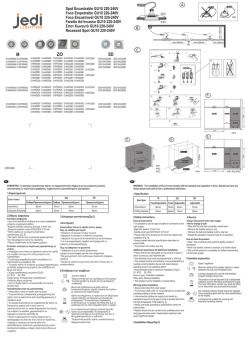
ALTEZZA TARGHE A 2 MODULI
HEIGHT OF 2-MODULE ENTRANCE PANELS
HAUTEUR PLAQUES DE RUE À 2 MODULES
HÖHE KLINGELTABLEAU MIT 2 MODULEN
ALTURA PLACAS DE 2 MÓDULOS
ALTURA DAS BOTONEIRAS COM 2 MÓDULOS
ȊȌȅȈȂȆȅȊȉȅȃǿǼȇȍȃȂȅȃǹǻȍȃ
TARGHE AUDIO/VIDEO PER UNITÀ ELETTRONICA, POSTO
ESTERNO AUDIO O TELECAMERA CON POSTO ESTERNO
AUDIO/VIDEO ENTRANCE PANELS FOR ELECTRONIC UNIT, AUDIO
SPEECH UNIT OR CAMERA WITH SPEECH UNIT
PLAQUES AUDIO/VIDÉO POUR UNITÉ ÉLECTRONIQUE, POSTE
EXTERNE AUDIO OU CAMÉRA AVEC POSTE EXTERNE
AUDIO/VIDEO-KLINGELTABLEAUS FÜR ELEKTRONIKEINHEIT,
AUSSENSPRECHSTELLE ODER KAMERA MIT
AUSSENSPRECHSTELLE
PLACAS AUDIO/VÍDEO PARA UNIDAD ELECTRÓNICA, APARATO
EXTERNO AUDIO O CÁMARA CON APARATO EXTERNO
BOTONEIRAS ÁUDIO/VÍDEO PARA UNIDADE ELECTRÓNICA, POSTO
EXTERNO ÁUDIO OU TELECÂMARA COM POSTO EXTERNO
ȂȆȅȊȉȅȃǿǼȇǼȈǾȋȅȊǼǿȀȅȃǹȈīǿǹǾȁǼȀȉȇȅȃǿȀǾȂȅȃǹǻǹ
ǼȄȍȉǼȇǿȀȅȈȉǹĬȂȅǾȋȅȊdzȀǹȂǼȇǹȂǼǼȄȍȉǼȇǿȀȅȈȉǹĬȂȅ
277
22
100
Art. 1321
Art. 132D
Art. 1331
Art. 133D
ALTEZZA TARGHE A 3 MODULI
HEIGHT OF 3-MODULE ENTRANCE PANELS
HAUTEUR PLAQUES DE RUE À 3 MODULES
HÖHE KLINGELTABLEAU MIT 3 MODULEN
ALTURA PLACAS DE 3 MÓDULOS
TARGHE SUPPLEMENTARI
ALTURA DAS BOTONEIRAS COM 3 MÓDULOS
SUPPLEMENTARY PUSH-BUTTON PANELS
ȊȌȅȈȂȆȅȊȉȅȃǿǼȇȍȃȂȅȃǹǻȍȃ
PLAQUES SUPPLÉMENTAIRES À BOUTONS
ZUSÄTZLICHE RUFTASTENTABLEAUS
PLACAS SUPLEMENTARIAS DE PULSADORES
BOTONEIRAS SUPLEMENTARES COM BOTÕES
ȈȊȂȆȁǾȇȍȂǹȉǿȀǼȈȂȆȅȊȉȅȃǿǼȇǼȈ
391
Art. 1358
22
6
Art. 132N
Art. 1372
Art. 133N
100
IT
EN
FR
DE
ES
PT
EL
1300
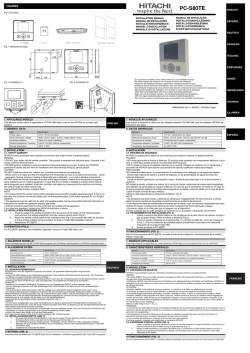
CORNICI PARAPIOGGIA - RAINPROOF COVERS - CADRES ANTI-PLUIE
5(*(16&+87=5$+0(10$5&26$17,//89,$$526$17,&+89$ȀȅȇȃǿǽǼȈȆȇȅȈȉǹȈǿǹȈǹȆȅȉǾǺȇȅȋǾ
C321
per 1 targa
for 1 panel
pour 1 plaque de rue
für 1 Klingeltableau
para 1 placa
para 1 botoneira
ȖȚĮȝʌȠȣIJȠȞȚȑȡĮ
C322
C323
C324
per 2 targhe
for 2 panels
pour 2 plaques de rue
für 2 Klingeltableaus
para 2 placas
para 2 botoneiras
ȖȚĮȝʌȠȣIJȠȞȚȑȡİȢ
per 3 targhe
for 3 panels
pour 3 plaques de rue
für 3 Klingeltableaus
para 3 placas
para 3 botoneiras
ȖȚĮȝʌȠȣIJȠȞȚȑȡİȢ
per 4 targhe
for 4 panels
pour 3 plaques de rue
für 4 Klingeltableaus
para 4 placas
para 4 botoneiras
ȖȚĮȝʌȠȣIJȠȞȚȑȡİȢ
alte 2 moduli
2 modules high
haute 2 modules
Höhe 2 Module
alta 2 módulos
alta 2 módulos
Ȫ
ȥȠȢȝȠȞȐįȦȞ
288
120
220
C331
per 1 targa
for 1 panel
pour 1 plaque de rue
für 1 Klingeltableau
para 1 placa
para 1 botoneira
ȖȚĮȝʌȠȣIJȠȞȚȑȡĮ
320
420
C332
C333
C334
per 2 targhe
for 2 panels
pour 2 plaques de rue
für 2 Klingeltableaus
para 2 placas
para 2 botoneiras
ȖȚĮȝʌȠȣIJȠȞȚȑȡİȢ
per 3 targhe
for 3 panels
pour 3 plaques de rue
für 3 Klingeltableaus
para 3 placas
para 3 botoneiras
ȖȚĮȝʌȠȣIJȠȞȚȑȡİȢ
per 4 targhe
for 4 panels
pour 3 plaques de rue
für 4 Klingeltableaus
para 4 placas
para 4 botoneiras
ȖȚĮȝʌȠȣIJȠȞȚȑȡİȢ
39
alte 3 moduli
3 modules high
haute 3 modules
Höhe 3 Module
alta 3 módulos
alta 3 módulos
Ȫ
ȥȠȢȝȠȞȐįȦȞ
402
120
IT
220
EN
FR
DE
ES
320
PT
EL
420
39
7
1300
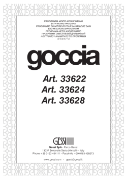
SCATOLE DA ESTERNO PARETE CON PARAPIOGGIA - SURFACE-MOUNTED BOXES WITH RAINPROOF COVER
BOÎTIERS POUR MONTAGE EN SAILLIE AVEC CADRE ANTI-PLUIE - AUFPUTZGEHÄUSE MIT REGENSCHUTZ
CAJAS DE SUPERFICIE CON MARCO ANTILLUVIA - CAIXAS DE MONTAGEM SALIENTE COM PROTECÇÃO ANTI-CHUVA
ǼȄȍȉǼȇǿȀǹǼȆǿȉȅǿȋǿǹȀȅȊȉǿǹȂǼȆȇȅȈȉǹȉǼȊȉǿȀȅǺȇȅȋǾȈ
S321
per 1 targa
for 1 panel
pour 1 plaque de rue
für 1 Klingeltableau
para 1 placa
para 1 botoneira
ȖȚĮȝʌȠȣIJȠȞȚȑȡĮ
S322
S323
S324
per 2 targhe
for 2 panels
pour 2 plaques de rue
für 2 Klingeltableaus
para 2 placas
para 2 botoneiras
ȖȚĮȝʌȠȣIJȠȞȚȑȡİȢ
per 3 targhe
for 3 panels
pour 3 plaques de rue
für 3 Klingeltableaus
para 3 placas
para 3 botoneiras
ȖȚĮȝʌȠȣIJȠȞȚȑȡİȢ
per 4 targhe
for 4 panels
pour 3 plaques de rue
für 4 Klingeltableaus
para 4 placas
para 4 botoneiras
ȖȚĮȝʌȠȣIJȠȞȚȑȡİȢ
alte 2 moduli
2 modules high
haute 2 modules
Höhe 2 Module
alta 2 módulos
alta 2 módulos
Ȫ
ȥȠȢȝȠȞȐįȦȞ
288
120
S331
per 1 targa
for 1 panel
pour 1 plaque de rue
für 1 Klingeltableau
para 1 placa
para 1 botoneira
ȖȚĮȝʌȠȣIJȠȞȚȑȡĮ
220
320
420
S332
S333
S334
per 2 targhe
for 2 panels
pour 2 plaques de rue
für 2 Klingeltableaus
para 2 placas
para 2 botoneiras
ȖȚĮȝʌȠȣIJȠȞȚȑȡİȢ
per 3 targhe
for 3 panels
pour 3 plaques de rue
für 3 Klingeltableaus
para 3 placas
para 3 botoneiras
ȖȚĮȝʌȠȣIJȠȞȚȑȡİȢ
per 4 targhe
for 4 panels
pour 3 plaques de rue
für 4 Klingeltableaus
para 4 placas
para 4 botoneiras
ȖȚĮȝʌȠȣIJȠȞȚȑȡİȢ
74
alte 3 moduli
3 modules high
haute 3 modules
Höhe 3 Module
alta 3 módulos
alta 3 módulos
Ȫ
ȥȠȢȝȠȞȐįȦȞ
402
120
8
220
320
420
IT
EN
74
FR
DE
ES
PT
EL
1300
MATERIALE FORNITO DI SERIE SULLE TARGHE SERIE 1300
COMPONENTS SUPPLIED AS STANDARD WITH ENTRANCE PANELS SÉRIE 1300
COMPOSANTS FOURNIS DE SÉRIE AVEC LES PLAQUES DE RUE SERIE 1300
STANDARDMÄSSIG MITGELIEFERTE KOMPONENTEN MIT KLINGELTABLEAUS BAUREIHE 1300
COMPONENTES SUMINISTRADOS DE SERIE CON LAS PLACAS SERIES 1300
MATERIAL FORNECIDO DE SÉRIE COM AS BOTONEIRAS DA SÉRIE 1300
ȊȁǿȀǹȆȅȊȆǹȇǼȋȅȃȉǹǿȍȈȉȊȆǿȀȅȈǼȄȅȆȁǿȈȂȅȈȈȉǿȈȂȆȅȊȉȅȃǿǼȇǼȈȈǼǿȇǹȈ
A
B
C
D
E
IT
EN
FR
DE
ES
PT
EL
ABCDE-
Placca frontale
Telaio
Staffetta con viti per fissaggio posto esterno audio
Mascherina di chiusura obiettivo
Anello per obietivo
ABCDE-
Front plate.
Frame.
Bracket with screws for fixing the speech unit.
Cover for closing the lens.
Ring for lens.
ABCDE-
Plaque frontale
Châssis
Étrier avec vis pour la fixation du poste externe audio
Masque de fermeture objectif
Bague pour objectif
ABCDE-
Frontblende
Rahmen
Halterung mit Schrauben für die Befestigung der Sprechstelle
Objektivabdeckung
Ring für Objektiv
ABCDE-
Plancha frontal
Bastidor
Soporte con tornillos para la fijación del aparato externo audio
Máscara de cierrre del objetivo
Anillo para el objetivo
ABCDE-
Botoneira frontal
Caixilho
Suporte com parafusos para fixação do posto externo áudio
Máscara de fecho da objectiva.
Anel para objectiva
A
B
C
D
E-
ȂʌȡȠıIJȚȞȒʌȜȐțĮ
ȆȜĮȓıȚȠ
ȈIJȒȡȚȖȝĮȝİȕȓįİȢȖȚĮıIJİȡȑȦıȘİȟȦIJİȡȚțȠȪıIJĮșȝȠȪȒȤȠȣ
ȀȐȜȣȝȝĮțȜİȚıȓȝĮIJȠȢijĮțȠȪ
ǻĮțIJȪȜȚȠȢȖȚĮijĮțȩ
9
1300
Materiale non fornito di serie da ordinare separatamente per predisporre una targa per sistemi sistemi digitali, Due Fili Elvox o Digibus:
Material not supplied as standard but to be ordered separately to prepare an entrance panel for Elvox Due Fili or Digibus digital systems:
Matériel non livré de série, à commander séparément pour prédisposer une plaque pour les systèmes numériques, Due Fili Elvox ou Digibus :
Das folgende Material ist nicht serienmäßig im Lieferumfang enthalten und muss separat bestellt werden, um ein Klingeltableau für digitale
Systeme Due Fili Elvox oder Digibus zusammenzustellen:
Material que no se suministra de serie y debe pedirse por separado para preparar una placa para sistemas digitales, Due Fili Elvox o Digibus:
Material não fornecido de série a encomendar separadamente para predispor uma botoneira para sistemas digitais, Due Fili Elvox ou Digibus:
ȊȜȚțȐʌȠȣįİȞʌĮȡȑȤȠȞIJĮȚȦȢIJȣʌȚțȩȢİȟȠʌȜȚıȝȩȢIJĮȠʌȠȓĮʌȡȑʌİȚȞĮIJĮʌĮȡĮȖȖİȓȜİIJİȟİȤȦȡȚıIJȐȖȚĮįȚĮȝȩȡijȦıȘȝȚĮȢȝʌȠȣIJȠȞȚȑȡĮȢȖȚĮ
ȥȘijȚĮțȐıȣıIJȒȝĮIJĮ'XH)LOL(OYR[Ȓ'LJLEXV
Per targa citofonica con pulsanti tradizionali:
For audio door entry panel with conventional buttons:
Pour plaque de poste d’appartement avec boutons traditionnels :
Für Audio-Klingeltableau mit traditionellen Tasten:
Para placa de portero automático con pulsadores tradicionales:
Para botoneira áudio com botões tradicionais:
īȚĮȝʌȠȣIJȠȞȚȑȡĮșȣȡȠIJȘȜȑijȦȞȠȣȝİıȣȝȕĮIJȚțȐȝʌȠȣIJȩȞ
R
S
I
L
Per targa videocitofonica con pulsanti tradizionali:
For video door entry panel with conventional buttons:
Pour plaque de portier-vidéo avec boutons traditionnels :
Für Video-Klingeltableau mit traditionellen Tasten:
Para placa de videoportero con pulsadores tradicionales:
Para botoneira vídeo com botões tradicionais:
īȚĮȝʌȠȣIJȠȞȚȑȡĮșȣȡȠIJȘȜİȩȡĮıȘȢȝİıȣȝȕĮIJȚțȐȝʌȠȣIJȩȞ
R
T
I
L
Per targa citofonica con
tastiera alfanumerica:
For audio door entry panel with
alphanumeric keypad:
Pour plaque de poste d’appartement
avec clavier alphanumérique :
Für Audio-Klingeltableau mit
alphanumerischer Tastatur:
Para placa de portero automático con
teclado alfanumérico:
Para botoneira áudio com
teclado alfanumérico:
īȚĮȝʌȠȣIJȠȞȚȑȡĮșȣȡȠIJȘȜȑijȦȞȠȣȝİ
ĮȜijĮȡȚșȝȘIJȚțȩʌȜȘțIJȡȠȜȩȖȚȠ
Per targa videocitofonica
con tastiera alfanumerica:
For video door entry panel
with alphanumeric keypad:
Pour plaque de portier-vidéo
avec clavier alphanumérique :
Für Video-Klingeltableau
mit alphanumerischer Tastatur:
Para placa de videoportero
con teclado alfanumérico:
Para botoneira vídeo
com teclado alfanumérico:
īȚĮȝʌȠȣIJȠȞȚȑȡĮșȣȡȠIJȘȜİȩȡĮıȘȢ
ȝİĮȜijĮȡȚșȝȘIJȚțȩʌȜȘțIJȡȠȜȩȖȚȠ
10
U
V
IT
EN
FR
DE
ES
PT
EL
1300
I-
L-
R-
STUV-
I-
L-
R-
ST-
UV-
Modulo copriforo per tasto esterno (fornito
separatamente). Da utilizzare per diminuire i
pulsanti di chiamata di una placca, sostituendo il
tasto con il modulo. Art. R130 (1 modulo).
Tasto esterno (fornito separatamente). Da utilizzare
per aumentare i pulsanti di chiamata di una placca,
sostituendo il modulo copriforo con il tasto. Il tasto
non prevede il pulsante sotostante. Art. R131 (1
tasto).
Modulo supplementere con 4 pulsanti per targhe
elettroniche Due Fili Elvox e Digibus, Art. 12TS
(fornito separatamente)
Unità elettronica audio a pulsanti Art. 13F3 (Due
Fili Elvox), Art. 1283 (Digibus)
Unità elettronica audio alfanumerica Art. 13F4 (Due
Fili Elvox), Art. 1882 (Digibus)
Unità elettronica video a pulsanti Art. 13F5 (Due Fili
Elvox), Art. 1285 (Digibus)
Unità elettronica video alfanumerica Art. 13F7 (Due
Fili Elvox), Art. 1286 (Digibus)
I-
Putzabdeckrahmen für Außentaste (separat
geliefert). Wird zur Reduzierung der
Ruftastenanzahl einer Platte durch Austausch
der Taste mit dem Modul verwendet. Art. R130 (1
Modul).
Außentaste (separat geliefert). Wird zur Erhöhung
der Ruftastenanzahl einer Platte durch Austausch
des Moduls mit der Taste verwendet. Bei der Taste
ist der darunter liegende Knopf nicht vorgesehen.
Art. R131 (1 Taste).
Zusatzmodul mit 4 Tasten für elektronische
Klingeltableaus Due Fili Elvox und Digibus, Art.
12TS (separat geliefert)
Audio-Elektronikeinheit mit Tasten Art. 13F3 (Due
Fili Elvox), Art. 1283 (Digibus)
Audio-Elektronikeinheit mit alphanumerischer
Tastatur Art. 13F4 (Due Fili Elvox), Art. 1882
(Digibus)
Video-Elektronikeinheit mit Tasten Art. 13F5 (Due
Fili Elvox), Art. 1285 (Digibus)
Video-Elektronikeinheit mit alphanumerischer
Tastatur Art. 13F7 (Due Fili Elvox), Art. 1286
(Digibus)
I-
L-
R-
STUV-
L-
R-
STU- V-
Blanking module for external key (supplied
separately). Used to reduce the number of call
buttons on a plate by replacing a key with the
module. Art. R130 (1 module).
External key (supplied separately). Used to
increase the number of call buttons on a plate by
replacing a blanking module with the key. The key
does not include the underlying push-button. Art.
R131 (1 key).
Supplementary module with 4 push-buttons for
Elvox Due Fili and Digibus electronic entrance
panels, Art. 12TS (supplied separately)
Push-button audio electronic unit Art. 13F3 (Elvox
Due Fili), Art. 1283 (Digibus)
Alphanumeric audio electronic unit Art. 13F4 (Elvox
Due Fili), Art. 1882 (Digibus)
Push-button video electronic unit Art. 13F5 (Elvox
Due Fili), Art. 1285 (Digibus)
Alphanumeric video electronic unit Art. 13F7 (Elvox
Due Fili), Art. 1286 (Digibus)
I-
Módulo ciego para tecla externa (se suministra
por separado). Se utiliza para disminuir el
número de pulsadores de llamada de una placa,
reemplazando la tecla por este módulo. Art. R130
(1 módulo).
Tecla externa (se suministra por separado). Se
utiliza para aumentar el número de pulsadores de
llamada de una placa, reemplazando el módulo
ciego por la tecla. La tecla no incluye el pulsador
de abajo. Art. R131 (1 tecla).
Módulo adicional con 4 pulsadores para placas
electrónicas Due Fili Elvox y Digibus, Art. 12TS (se
suministra por separado)
Unidad electrónica audio con pulsadores Art. 13F3
(Due Fili Elvox), Art. 1283 (Digibus)
Unidad electrónica audio alfanumérica Art. 13F4
(Due Fili Elvox), Art. 1882 (Digibus)
Unidad electrónica vídeo con pulsadores Art. 13F5
(Due Fili Elvox), Art. 1285 (Digibus)
Unidad electrónica vídeo alfanumérica Art. 13F7
(Due Fili Elvox), Art. 1286 (Digibus)
I-
L-
R-
STUV-
L-
R-
STUV-
Module cache-trou pour touche externe (fourni
séparément). À utiliser pour réduire le nombre des
boutons d’appel d’une plaque, en remplaçant la
touche par le module. Art. R130 (1 module).
Touche externe (fournie séparément). À utiliser
pour augmenter les boutons d’appel d’une plaque,
en remplaçant le module cache-trou par la touche.
La touche ne prévoit pas le bouton sous-jacent. Art.
R131 (1 touche).
Module supplémentaire avec 4 boutons pour
plaques électroniques Due Fili Elvox et Digibus,
Art. 12TS (fourni à part)
Unité électronique audio à boutons Art. 13F3
(Due Fili Elvox), Art. 1283 (Digibus)
Unité électronique audio alphanumérique Art.
13F4 (Due Fili Elvox), Art. 1882 (Digibus)
Unité électronique vidéo à boutons Art. 13F5
(Due Fili Elvox), Art. 1285 (Digibus)
Unité électronique vidéo alphanumérique Art.
13F7 (Due Fili Elvox), Art. 1286 (Digibus)
Módulo de tampa cega para tecla externa
(fornecido em separado). A utilizar para diminuir os
botões de chamada de um espelho, substituindo a
tecla pelo módulo. Art. R130 (1 módulo).
Tecla externa (fornecida em separado). A utilizar
para aumentar os botões de chamada de um
espelho, substituindo o módulo de tampa cega
pela tecla. A tecla não prevê o botão subjacente.
Art. R131 (1 tecla).
Módulo suplementar com 4 botões para botoneiras
electrónicas Due Fili Elvox e Digibus, Art. 12TS
(fornecido em separado)
Unidade electrónica áudio de botões Art. 13F3
(Due Fili Elvox), Art. 1283 (Digibus)
Unidade electrónica áudio alfanumérica Art. 13F4
(Due Fili Elvox), Art. 1882 (Digibus)
Unidade electrónica vídeo de botões Art. 13F5
(Due Fili Elvox), Art. 1285 (Digibus)
Unidade electrónica vídeo alfanumérica Art. 13F7
(Due Fili Elvox), Art. 1286 (Digibus)
I ȂȠȞȐįĮ țĮȜȪȝȝĮIJȠȢ ȖȚĮ İȟȦIJİȡȚțȩ ʌȜȒțIJȡȠ
ʌĮȡȑȤİIJĮȚȟİȤȦȡȚıIJȐȋȡȘıȚȝȠʌȠȚİȓIJĮȚȖȚĮȝİȓȦıȘ
IJȠȣĮȡȚșȝȠȪIJȦȞʌȜȒțIJȡȦȞțȜȒıȘȢȝȚĮȢʌȜȐțĮȢ
ĮȞIJȚțĮșȚıIJȫȞIJĮȢIJȠʌȜȒțIJȡȠȝİIJȘȝȠȞȐįĮȀȦį
R130ȝȠȞȐįĮ
L ǼȟȦIJİȡȚțȩ ʌȜȒțIJȡȠ ʌĮȡȑȤİIJĮȚ ȟİȤȦȡȚıIJȐ
ȋȡȘıȚȝȠʌȠȚİȓIJĮȚ ȖȚĮ ĮȪȟȘıȘ IJȠȣ ĮȡȚșȝȠȪ IJȦȞ
ʌȜȒțIJȡȦȞțȜȒıȘȢȝȚĮȢʌȜȐțĮȢĮȞIJȚțĮșȚıIJȫȞIJĮȢ
IJȘȝȠȞȐįĮțĮȜȪȝȝĮIJȠȢȝİIJȠʌȜȒțIJȡȠȉȠʌȜȒțIJȡȠ
įİȞʌİȡȚȜĮȝȕȐȞİȚIJȠțȐIJȦȝʌȠȣIJȩȞȀȦį5
ʌȜȒțIJȡȠ
R - ȈȣȝʌȜȘȡȦȝĮIJȚțȒ ȝȠȞȐįĮ ȝİ ȝʌȠȣIJȩȞ ȖȚĮ
ȘȜİțIJȡȠȞȚțȑȢ ȝʌȠȣIJȠȞȚȑȡİȢ 'XH )LOL (OYR[ țĮȚ
'LJLEXVțȦį76ʌĮȡȑȤİIJĮȚȟİȤȦȡȚıIJȐ
S ǾȜİțIJȡȠȞȚțȒȝȠȞȐįĮȒȤȠȣȝİȝʌȠȣIJȩȞțȦį)
(Due Fili ElYR[țȦį'LJibus)
T ǹȜijĮȡȚșȝȘIJȚțȒ ȘȜİțIJȡȠȞȚțȒ ȝȠȞȐįĮ ȒȤȠȣ țȦį
13F4 (DXH)LOL(OYR[ȒțȦį. 1882 (Digibus)
U - ǾȜİțIJȡȠȞȚțȒ ȝȠȞȐįĮ İȚțȩȞĮȢ ȝİ ȝʌȠȣIJȩȞ țȦį
13F5 (Due Fili EOYR[țȦį'Lgibus)
V ǹȜijĮȡȚșȝȘIJȚțȒȘȜİțIJȡȠȞȚțȒȝȠȞȐįĮİȚțȩȞĮȢțȦį
13F'XH)LOL(OYR[ȒțȦį'LJLEXV
IT
EN
FR
DE
ES
PT
EL
11
1300
Materiale non fornito di serie da ordinare separatamente per predisporre una targa per sistemi Sound System e c.a.
Material not supplied as standard but to be ordered separately to prepare an entrance panel for Sound System and c.a. systems
Pièce non livrée de série, à commander séparément pour prédisposer une plaque pour les systèmes Sound System et c.a.
Das folgende Material ist nicht serienmäßig im Lieferumfang enthalten und muss separat bestellt werden, um ein Klingeltableau für die Systeme
Sound System und Wechselstromruf zusammenzustellen.
Material que no se suministra de serie y debe pedirse por separado para preparar una placa para sistemas Sound System y c.a.
Material não fornecido de série a encomendar separadamente para predispor uma botoneira para sistemas Sound System e c.a.
ȊȜȚțȐʌȠȣįİȞʌĮȡȑȤȠȞIJĮȚȦȢIJȣʌȚțȩȢİȟȠʌȜȚıȝȩȢIJĮȠʌȠȓĮʌȡȑʌİȚȞĮIJĮʌĮȡĮȖȖİȓȜİIJİȟİȤȦȡȚıIJȐȖȚĮįȚĮȝȩȡijȦıȘȝȚĮȢȝʌȠȣIJȠȞȚȑȡĮȢȖȚĮ
ıȣıIJȒȝĮIJĮ6RXQG6\VWHPțĮȚFD
- Per targa citofonica.: - For audio door entry panel: - Pour plaque de poste d’appartement : - Für Audio-Klingeltableau:
3DUDSODFDGHSRUWHURDXWRPiWLFR3DUDERWRQHLUDiXGLRīȚĮȝʌȠȣIJȠȞȚȑȡĮșȣȡȠIJȘȜȑijȦȞȠȣ
H
F
G
L
I
- Per targa videocitofonica.: - For video door entry panel: Pour plaque de portier-vidéo : - Für Video-Klingeltableau:
3DUDSODFDGHYLGHRSRUWHUR3DUDERWRQHLUDYtGHRīȚĮȝʌȠȣIJȠȞȚȑȡĮșȣȡȠIJȘȜİȩȡĮıȘȢ
H
- M
V
+T
8
7
6
5
M
12
G
L
I
IT
EN
FR
DE
ES
PT
EL
1300
F - Posto esterno audio (fornito separatamente), Art.
930A, 930B, 930C, 930D, 930F, 930G
G - Pulsanti (forniti separatamente), Art. R200 (1 pulsante) o R200/50 (50 pulsanti)
H - Scheda di illuminazione a LED per cartellini portanomi (fornita separatamente), Art. R260
I - Modulo copriforo per tasto esterno (fornito separatamente). Da utilizzare per diminuire i pulsanti
di chiamata di una placca, sostituendo il tasto con
il modulo. Art. R130 (1 modulo).
L - Tasto esterno (fornito separatamente). Da utilizzare per aumentare i pulsanti di chiamata di
una placca, sostituendo il modulo copriforo con il
tasto. Il tasto non prevede il pulsante sotostante.
Art. R131 (1 tasto).
M - Telecamera con posto esterno audio (fornito separatamente), Art. 559A, Art. 559B, Art. 560A per
impianti con o senza cavo coassiale
F - Poste externe audio (fourni séparément), Art. 930A,
930B, 930C, 930D, 930F, 930G
G - Boutons-poussoirs (fournis séparément), Art.
R200 (1 bouton-poussoir) ou R200/50 (50 boutons-poussoirs)
H - Carte d’éclairage à LED pour étiquette porte-noms
(fournie séparément), Art. R260.
I - Module cache-trou pour touche externe (fourni
séparément). À utiliser pour diminuer les boutons
d’appel d’une plaque, en remplaçant la touche par
le module. Art. R130 (1 module)
L - Touche externe (fournie séparément). À utiliser
pour augmenter les boutons d’appel d’une plaque,
en remplaçant le module cache-trou par la touche.
La touche ne prévoit pas le bouton sous-jacent.
Art. R131 (1 touche).
M - Caméra avec poste externe audio (fournie
séparément) Art. 559A, Art. 559B, Art. 560A avec
o sans câble coaxial
F - Speech unit (supplied separately) Art. 930A, Art.
930B, Art. 930C, Art. 930D, Art. 930F, 930G
G - Push-buttons (supplied separately), Art. R200 (1
push-button) or R200/50 (50 push-buttons).
H - Led lighting card for name-tags (supplied separately), Art. R260.
I - Blanking module for external key (purchased
separately). Used to reduce the number of call
buttons on a plate by replacing a key with the module. Type R130 (1 module).
L - External key (purchased separately). Used to increase the number of call buttons on a plate by
replacing a blanking module with the key. The key
does not include underlying push-button. Type
R131 (1 key).
M - Camera with speech unit (supplied separately)
Art. 559A, Art. 559B, 560A for system with or without cable coaxial
F - Sprechstelle (separat geliefert) Art. 930A, Art.
930B, Art. 930C, Art. 930D, Art. 930F, 930G
G - Tasten (separat geliefert), Art. R200 (1 Taste)
oder R200/50 (50 Taste)
H - Karte mit LED für die Namensschildbeleuchtung
(separat geliefert), Art. R260.
I - Blindabdeckung für Taste mit Namensschild (separat geliefert). Wird zur Reduzierung der Ruftastenanzahl einer Platte durch Austausch der Taste
mit der Blindabdeckung verwendet. Art. R130 (1
Abdeckung).
L - Taste mit Namensschild (separat geliefert). Wird
zur Erhöhung der Ruftastenanzahl einer Platte
durch Austausch der Abdeckung mit der Taste
verwendet. Bei der Taste ist der darunter liegende
interne Taster nicht enthalten. Art. R131 (1 Taste).
M - Kamera mit Sprechstelle (separat geliefert) Art.
559A, Art. 559B, Art. 560A mit oder ohne Koaxialkabel
F - Aparato externo de audio (suministrado por separado) Art. 930A, 930B, 930C, 930D, 930F, 930G
G - Pulsadores (suministrados por separado), Art.
R200 (1 pulsador) o R200/50 (50 pulsadores).
H - Ficha de iluminación con Led para tarjeta portanombres (suministrada por separado), Art. R260.
I - Módulo embellecedor para tecla externa (se suministra por separado). Se utiliza para disminuir
los pulsadores de llamada de una placa, reemplazando la tecla por este módulo Art. R130 (1
módulo).
L - Tecla externa (se suministra por separado). Se
utiliza para aumentar los pulsadores de llamada
de una placa, reemplazando el módulo embellecedor por la tecla. La tecla no incluye el pulsador
de abajo. Art. R131 (1 tecla).
M - Cámara con aparato externo audio (suministrado
por separado) Art. 559A, 559B, 560A para con o
sin coax. cable
F - Posto externo audio (fornecido separadamente)
Art. 930A, 930B, 930C, 930D, 930F, 930G
G - Botões (fornecidos separadamente) Art. R200 (1
botão) ou R200/50 (50 botões)
H - Placa de iluminação com LED para cartões porta-nomes (fornecida separadamente) Art. R260.
I - Módulo de cobertura do orifício para botão externo (fornecido separadamente). A utilizar para
diminuir os botões de chamada de uma placa,
substituindo o botão pelo módulo. Art. R130 (1
módulo).
L - Botão externo (fornecido separadamente). A utilizar para aumentar os botões de chamada de
uma placa, substituindo o módulo de cobertura
do orifício pelo botão. A tecla não prevê o botão
subjacente. Art. R131 (1 botão).
M - Telecâmara com posto externo audio (fornecida
separadamente) Art. 559A, Art. 559B, 560A, para
ou sem cabo coaxial.
F ǼȟȦIJİȡȚțȩȢıIJĮșȝȩȢȒȤȠȣʌĮȡȑȤİIJĮȚȟİȤȦȡȚıIJȐ
țȦį$0B, 930C, 930D, 930F, 930G
G ȂʌȠȣIJȩȞʌĮȡȑȤȠȞIJĮȚȟİȤȦȡȚıIJȐțȦį5
ȝʌȠȣIJȩȞȒ5ȝʌȠȣIJȩȞ
H ȆȜĮțȑIJĮ ijȦIJȚıȝȠȪ ȝİ ȜȣȤȞȓİȢ /(' ȖȚĮ İIJȚțȑIJİȢ
ȠȞȩȝĮIJȠȢʌĮȡȑȤİIJĮȚȟİȤȦȡȚıIJȐțȦį5
I ȂȠȞȐįĮ țĮȜȪȝȝĮIJȠȢ ȖȚĮ İȟȦIJİȡȚțȩ ʌȜȒțIJȡȠ
ʌĮȡȑȤİIJĮȚ ȟİȤȦȡȚıIJȐ ȋȡȘıȚȝȠʌȠȚİȓIJĮȚ ȖȚĮ
ȝİȓȦıȘ IJȠȣ ĮȡȚșȝȠȪ IJȦȞ ʌȜȒțIJȡȦȞ țȜȒıȘȢ
ȝȚĮȢʌȜȐțĮȢĮȞIJȚțĮșȚıIJȫȞIJĮȢIJȠʌȜȒțIJȡȠȝİIJȘ
ȝȠȞȐįĮȀȦį5ȝȠȞȐįĮ
L ǼȟȦIJİȡȚțȩ ʌȜȒțIJȡȠ ʌĮȡȑȤİIJĮȚ ȟİȤȦȡȚıIJȐ
ȋȡȘıȚȝȠʌȠȚİȓIJĮȚ ȖȚĮ ĮȪȟȘıȘ IJȠȣ ĮȡȚșȝȠȪ IJȦȞ
ʌȜȒțIJȡȦȞțȜȒıȘȢȝȚĮȢʌȜȐțĮȢĮȞIJȚțĮșȚıIJȫȞIJĮȢ
IJȘȝȠȞȐįĮțĮȜȪȝȝĮIJȠȢȝİIJȠʌȜȒțIJȡȠȉȠʌȜȒțIJȡȠ
įİȞʌİȡȚȜĮȝȕȐȞİȚIJȠțȐIJȦȝʌȠȣIJȩȞȀȦįR131 (1
ʌȜȒțIJȡȠ
M ȀȐȝİȡĮ ȝİ İȟȦIJİȡȚțȩ ıIJĮșȝȩ ȒȤȠȣ ʌĮȡȑȤİIJĮȚ
ȟİȤȦȡȚıIJȐ țȦį $ țȦį % țȦį $
ȖȚĮİȖțĮIJĮıIJȐıİȚȢȝİȒȤȦȡȓȢȠȝȠĮȟȠȞȚțȩțĮȜȫįȚȠ
IT
EN
FR
DE
ES
PT
EL
13
1300
MATERIALE NON FORNITO DI SERIE DA ORDINARE SEPARATAMENTE PER
PREDISPORRE UNA TARGA DA INCASSO PARETE
MATERIALE NON FORNITO DI SERIE DA ORDINARE SEPARATAMENTE PER
PREDISPORRE UNA TARGA DA ESTERNO PARETE
COMPONENTS NOT SUPPLIED AS STANDARD AND TO BE ORDERED
SEPARATELY IN ORDER TO PRESET ONE FLUSH-MOUNTED ENTRANCE
PANEL
COMPONENTS NOT SUPPLIED AS STANDARD AND TO BE ORDERED
SEPARATELY IN ORDER TO PRESET ONE SURFACE WALL-MOUNTED
ENTRANCE PANEL
COMPOSANTS NON FOURNIS DE SÉRIE À COMMANDER SÉPARÉMENT POUR
PRÉDISPOSER UNE PLAQUE DE RUE POUR MONTAGE À ENCASTRER
COMPOSANTS NON FOURNIS DE SÉRIE À COMMANDER SÉPARÉMENT POUR
PRÉDISPOSER UNE PLAQUE DE RUE POUR MONTAGE EN SAILLIE
NICHT STANDARDMÄSSIG MITGELIEFERTE UND GETRENNT ZU
BESTELLENDE KOMPONENTEN UM EIN UP-KLINGELTABLEAU
VORZUBEREITEN
NICHT STANDARDMÄSSIG MITGELIEFERTE UND GETRENNT ZU
BESTELLENDE KOMPONENTEN UM EIN AP-KLINGELTABLEAU
VORZUBEREITEN
MATERIAL NO SUMINISTRADO DE SERIE PARA PEDIR POR SEPARADO PARA
PREDISPONER UNA PLACA DE EMPOTRE
MATERIAL NO SUMINISTRADO DE SERIE PARA PEDIR POR SEPARADO PARA
PREDISPONER UNA PLACA DE SUPERFICIE
MATERIAL NÃO FORNECIDO DE SÉRIE E A PEDIR SEPARADAMENTE PARA
PREDISPOR UMA BOTONEIRA DE EMBEBER
MATERIAL NÃO FORNECIDO DE SÉRIE E A PEDIR SEPARADAMENTE PARA
PREDISPOR UMA BOTONEIRA DE MONTAGEM SALIENTE
ȊȁǿȀǹȆȅȊǻǼȃȆǹȇǼȋȅȃȉǹǿȍȈȉȊȆǿȀȅȈǼȄȅȆȁǿȈȂȅȈȉǹȅȆȅǿǹ
ȆȇǼȆǼǿȃǹȉǹȆǹȇǹīīǼǿȁǼȉǼȄǼȋȍȇǿȈȉǹīǿǹǻǿǹȂȅȇĭȍȈǾȂǿǹȈ
ȋȍȃǼȊȉǾȈǼȆǿȉȅǿȋǿǹȈȂȆȅȊȉȅȃǿǼȇǹȈ
ȊȁǿȀǹȆȅȊǻǼȃȆǹȇǼȋȅȃȉǹǿȍȈȉȊȆǿȀȅȈǼȄȅȆȁǿȈȂȅȈȉǹȅȆȅǿǹȆȇǼȆǼǿ
ȃǹ ȉǹ ȆǹȇǹīīǼǿȁǼȉǼ ȄǼȋȍȇǿȈȉǹ īǿǹ ǻǿǹȂȅȇĭȍȈǾ ȂǿǹȈ ǼȄȍȉǼȇǿȀǾȈ
ǼȆǿȉȅǿȋǿǹȈȂȆȅȊȉȅȃǿǼȇǹȈ
O
P
N
N - Scatola da incasso (fornita separatamente) art. 9192 (per 2 moduli verticali) o
9193 (per 3 moduli verticali)
O - Cornice parapioggia per installazione da incasso parete (fornita separatamente)
art. C321, C322, C323, C324 (2 moduli verticali)
art. C331, C332, C333, C334 (3 moduli verticali)
P - Scatola con cornice parapioggia per installazione targa da esterno parete (fornita
separatamente)
art. S321, S322, S323, S324 (2 moduli verticali)
art. S331, S332, S333, S334 (3 moduli verticali)
N - Flush-mounted box (supplied separately) type 9192 (for 2 vertical modules) or
9193 (for 3 vertical modules)
O - Rainproof cover for surface-mounted installation (supplied separately)
type C321, C322, C323, C324 (2 vertical modules)
type C331, C332, C333, C334 (3 vertical modules)
P - Box with rainproof cover for surface wall-mounted entrance panel installation
(supplied separately)
type S321, S322, S323, S324 (2 vertical modules)
type S331, S332, S333, S334 (3 vertical modules)
N - Boîtier à encastrer (fourni séparément) art. 9192 (pour 2 modules verticaux) ou
9193 (pour 3 modules verticaux)
O - Cadre anti-pluie pour pour encastrement mural (fourni séparément)
art. C321, C322, C323, C324 (2 modules verticaux)
art. C331, C332, C333, C334 (3 modules verticaux)
P - Boîtier avec cadre anti-pluie pour montage plaque en saillie (fourni séparément)
art. S321, S322, S323, S324 (2 modules verticaux)
art. S331, S332, S333, S334 (3 modules verticaux)
N - Caja de empotrar (suministrada por separado) art. 9192 (para 2 módulos verticales)
o 9193 (para 3 módulos verticales)
O - Marco antilluvia para placa empotrada (suministrado por separado)
art. C321, C322, C323 y C324 (2 módulos verticales)
art. C331, C332, C333 y C334 (3 módulos verticales)
P - Caja con marco antilluvia para placa de superficie (suministrada por separado)
art. S321, S322, S323 y S324 (2 módulos verticales)
art. S331, S332, S333 y S334 (3 módulos verticales)
N - Caixa de embeber (fornecida separadamente) Art. 9192 (para 2 módulos verticais)
ou 9193 (para 3 módulos verticais)
O - Aro anti-chuva para instalação duma botoneira de embeber (fornecido
separadamente)
Art. C321, C322, C323, C324 (2 módulos verticais)
Art. C331, C332, C333, C334 (3 módulos verticais)
P - Caixa com aro anti-chuva para instalação de montagem saliente (fornecido
separadamente)
Art. S321, S322, S323, S324 (2 módulos verticais)
Art. S331, S332, S333, S334 (3 módulos verticais)
N ȋȦȞİȣIJȩțȠȣIJȓʌĮȡȑȤİIJĮȚȟİȤȦȡȚıIJȐțȦįȖȚĮțĮIJĮțȩȡȣijİȢȝȠȞȐįİȢȒ
9193ȖȚĮțĮIJĮțȩȡȣijİȢȝȠȞȐįİȢ
O ȀȠȡȞȓȗĮ ȖȚĮ ʌȡȠıIJĮıȓĮ Įʌȩ IJȘ ȕȡȠȤȒ ȖȚĮ ȤȦȞİȣIJȒ İʌȚIJȠȓȤȚĮ İȖțĮIJȐıIJĮıȘ
ʌĮȡȑȤİIJĮȚȟİȤȦȡȚıIJȐ
țȦį&&&&țĮIJĮțȩȡȣijİȢȝȠȞȐįİȢ
țȦį&&&&țĮIJĮțȩȡȣijİȢȝȠȞȐįİȢ
P ȀȠȣIJȓ ȝİ țȠȡȞȓȗĮ ȖȚĮ ʌȡȠıIJĮıȓĮ Įʌȩ IJȘ ȕȡȠȤȒ ȖȚĮ İȖțĮIJȐıIJĮıȘ İȟȦIJİȡȚțȒȢ
İʌȚIJȠȓȤȚĮȢȝʌȠȣIJȠȞȚȑȡĮȢʌĮȡȑȤİIJĮȚȟİȤȦȡȚıIJȐ
țȦį6321, S322, S323, S32țĮIJĮțȩȡȣijİȢȝȠȞȐįİȢ
țȦį6666țĮIJĮțȩȡȣijİȢȝȠȞȐįİȢ
N - Unterputzgehäuse (separat geliefert) Art. 9192 (für 2 vertikale Module) oder 9193
(für 3 vertikale Module)
O - Regenschutzrahmen für die Unterputzinstallation (separat geliefert)
Art. C321, C322, C323, C324 (2 vertikale Module)
Art. C331, C332, C333, C334 (3 vertikale Module)
P - Gehäuse mit Regenschutzrahmen für die Aufputzinstallation (separat
geliefert)
Art. S321, S322, S323, S324 (2 vertikale Module)
Art. S331, S332, S333, S334 (3 vertikale Module)
14
IT
EN
FR
DE
ES
PT
EL
1300
Estrazione del modulo copriforo per tasto esterno, per aumentare i tasti
di chiamata con tasto esterno art. R131 nelle placche Art. 1321, 1331.
Altezza di installazione di una targa
Height of installation of an entrance panel
Removing the blanking module for an external key to increase the
number of call keys with an external key art. R131 on plates Art. 1321,
1331.
Hauteur d’installation d’une plaque
Installationshöhe eines Klingeltableaus
Altura de montaje de una placa
Extraction du module cache-trou pour touche extérieure, pour
augmenter les touches d’appel avec touche extérieure art. R131 sur
les plaques Art. 1321, 1331.
Altura de instalação de uma botoneira
ǶȥȠȢİȖțĮIJȐıIJĮıȘȢȝʌȠȣIJȠȞȚȑȡĮȢ
Fig. 0
Entnahme des Putzabdeckrahmens für die Außentaste zur Erhöhung
der Ruftastenanzahl mit Außentaste Art. R131 in den Frontplatten Art.
1321, 1331.
1m
Extracción del módulo ciego para tecla externa, para aumentar el
número de teclas de llamada con la tecla externa Art. R131 en las
placas Art. 1321, 1331.
Extracção do módulo de tampa cega para tecla externa, para aumentar
as teclas de chamada com tecla externa art. R131 nos espelhos Art.
1321, 1331.
ǹijĮȓȡİıȘȝȠȞȐįĮȢțĮȜȪȝȝĮIJȠȢȖȚĮİȟȦIJİȡȚțȩʌȜȒțIJȡȠȖȚĮĮȪȟȘıȘIJȠȣ
ĮȡȚșȝȠȪIJȦȞʌȜȒțIJȡȦȞțȜȒıȘȢȝİİȟȦIJİȡȚțȩʌȜȒțIJȡȠțȦį5ıIJȚȢ
ʌȜȐțİȢțȦį
2,04m
1,65m
Fig. 5
1,04m
4
3
2
1
Inserimento di una unità elettronica audio/video per sistemi digitali
o di una telecamera con posto esterno per sistemi Sound System
Inserting an electronic audio/video unit for digital systems or a
camera with a speech unit for Sound Systems
Insertion d’une unité électronique audio/vidéo pour systèmes
numériques ou d’une caméra avec poste externe pour systèmes
Sound System
Einsetzen einer Audio-/Video-Elektronikeinheit für digitale Systeme
bzw. einer Kamera mit Außensprechstelle für Systeme Sound System
Colocación de una unidad electrónica audio/vídeo para sistemas
digitales o de una cámara con aparato externo para sistemas Sound
System
Inserção de uma unidade electrónica áudio/vídeo para sistemas
digitais ou de uma telecâmara com posto externo para sistemas
Sound System
ȉȠʌȠșȑIJȘıȘ ȘȜİțIJȡȠȞȚțȒȢ ȝȠȞȐįĮȢ ȒȤȠȣİȚțȩȞĮȢ ȖȚĮ ȥȘijȚĮțȐ
ıȣıIJȒȝĮIJĮȒțȐȝİȡĮȢȝİİȟȦIJİȡȚțȩıIJĮșȝȩȖȚĮıȣıIJȒȝĮIJĮ6RXQG
System
Fig. 1
IT
EN
FR
DE
ES
PT
EL
15
1300
Nel caso di targa citofonica si deve togliere l’anello dal retro della
placca frontale (Rif. 1, Fig.6), inserire al suo posto la mascherina di
chiusura obiettivo (Rif. 2, Fig.6)
Vite di fissaggio della placca al telaio, per apertura/chiusura targa
In the case of an audio door entry panel you need to remove the ring
from the back of the front plate (Ref. 1, Fig.6) and in its place insert the
cover for closing the lens (Ref. 2, Fig.6)
Vis de fixation de la plaque au châssis, pour ouverture/fermeture de
la plaque
Dans le cas d’une plaque de poste d’appartement, ôter l’anneau par
l’arrière de la plaque frontale (Rep. 1, Fig.6) et le remplacer par le cache
fermant l’objectif (Rep. 2, Fig.6)
Im Falle eines Audio-Klingeltableaus muss der Ring an der Rückseite
der Frontplatte (Nr. 1, Abb. 6) entfernt, und an seiner Stelle die ObjektivAbdeckblende (Nr. 2, Abb. 6) eingesetzt werden
En caso de placa de portero automático, hay que retirar el anillo desde
la parte trasera de la placa frontal (Ref. 1, Fig. 6) e introducir en su
lugar la tapa del objetivo (Ref. 2, Fig. 6)
Screw securing the plate to the frame, for opening/closing the entrance
panel
Befestigungsschraube der Frontplatte am Trägerrahmen, zum Öffnen/
Schließen des Klingeltableaus
Tornillo de fijación de la placa al bastidor, para abrir/cerrar la placa
Parafuso de fixação do espelho ao caixilho, para abertura/fecho da
botoneira
ǺȓįĮ ıIJİȡȑȦıȘȢ ʌȜȐțĮȢ ıIJȠ ʌȜĮȓıȚȠ ȖȚĮ ȐȞȠȚȖȝĮțȜİȓıȚȝȠ
ȝʌȠȣIJȠȞȚȑȡĮȢ
Fig. 8
No caso da botoneira áudio, deve-se retirar o anel da parte de trás do
espelho frontal (Ref. 1, Fig.6), e inserir no seu lugar a tampa de fecho
da objectiva (Ref. 2, Fig.6)
ȈIJȘȞ ʌİȡȓʌIJȦıȘ IJȘȢ ȝʌȠȣIJȠȞȚȑȡĮȢ șȣȡȠIJȘȜȑijȦȞȠȣ ʌȡȑʌİȚ ȞĮ
ĮijĮȚȡȑıİIJİIJȠįĮțIJȪȜȚȠĮʌȩIJȠʌȓıȦȝȑȡȠȢIJȘȢȝʌȡȠıIJȚȞȒȢʌȜȐțĮȢ
ĮȞĮij İȚț țĮȚ ȞĮ IJȠʌȠșİIJȒıİIJİ ıIJȘ șȑıȘ IJȠȣ IJȠ țȐȜȣȝȝĮ
țȜİȚıȓȝĮIJȠȢijĮțȠȪĮȞĮijİȚț
Fig. 6
2
E
1
D
Nota: Solo nelle unità elettroniche per sistemi Digibus e necessario sfilare o
tagliare il tappo in gomma (preesistente nei posti esterni audio o telecamere)
facendo attenzione a non tagliare i cavi del microfono.
Note: Only on the electronic units for Digibus systems is it necessary to take
out or cut the rubber cap (existing on audio speech units or cameras), taking
care not to cut the wires of the microphone.
Alloggiamento del microfono
Remarque : Sur les unités électroniques des systèmes Digibus uniquement,
dégager ou couper le bouchon en caoutchouc (déjà présent sur les postes
externes audio ou caméras) en ayant soin de ne pas couper les câbles du
micro.
Microphone housing
Logement du micro
Mikrofon-Aufnahme
Hinweis: Nur bei Elektronikeinheiten für Systeme Digibus muss der
Gummideckel abgenommen oder abgeschnitten werden (bereits vorhanden
an Außensprechstellen oder Kameras. Vorsicht, nicht die Mikrofonkabel
durchschneiden.
Alojamiento del micrófono
Alojamento do microfone
ȊʌȠįȠȤȒȝȚțȡȠijȫȞȠȣ
Nota: Solo en las unidades electrónicas para sistemas Digibus es necesario
sacar o cortar el tapón de goma (ya colocado en los aparatos externos audio
o cámaras) teniendo cuidado de no cortar los cables del micrófono.
Fig. 7
Nota: Apenas nas unidades electrónicas para sistemas Digibus é
necessário puxar ou retirar o tampão de borracha (pré-existente nos postos
externos áudio ou telecâmaras), tendo o cuidado de não cortar os cabos
do microfone.
Part. 1
16
ȈȘȝİȓȦıȘ ȂȩȞȠ ıIJȚȢ ȘȜİțIJȡȠȞȚțȑȢ ȝȠȞȐįİȢ ȖȚĮ ıȣıIJȒȝĮIJĮ 'LJLEXV
ʌȡȑʌİȚȞĮĮijĮȚȡȑıİIJİȒȞĮțȩȥİIJİIJȠİȜĮıIJȚțȩʌȫȝĮʌȡȠȨʌȐȡȤİȚıIJȠȣȢ
İȟȦIJİȡȚțȠȪȢıIJĮșȝȠȪȢȒȤȠȣȒıIJȚȢțȐȝİȡİȢijȡȠȞIJȓȗȠȞIJĮȢȞĮȝȘȞțȩȥİIJİIJĮ
țĮȜȫįȚĮIJȠȣȝȚțȡȠijȫȞȠȣ
IT
EN
FR
DE
ES
PT
EL
1300
Installazione delle targhe serie 1300 in sistemi Due Fili o
Digibus.
-
Installare a muro la scatola da incasso (N) o la scatola da esterno parete
(P) ad una altezza di circa 1,65m dal bordo superiore della scatola al
pavimento.
Nota: Le targhe della serie 1300 possono essere ampliate solo in senso
orizzontale con targhe supplementari. Nel caso di installazione da
incasso le scatole vanno abbinate per mezzo degli appositi agganci forniti
con le scatole stesse (vedi fig. 30).
Fissare la morsettiera dell’unità elettronica sotto il telaio portamoduli, per
mezzo delle viti in dotazione.
Nel caso di installazione da incasso parete:
- Fissare l’eventuale cornice parapioggia (O) alla scatola da incasso (N).
- Fissare il telaio (B) alla scatola da incasso (N) o alla cornice parapioggia.
Nel caso di installazione da esterno parete:
- Fissare il telaio (B) alla scatola da esterno.
Collegare la morsettiera dell’unità elettronica all’impianto, seguendo gli
schemi di collegamento nel manuale di riferimento a seconda della tipo
di impianto.
Collegare l’unità elettronica (S, T/U, V) alla morsettiera per mezzo del
cablaggio presente nel lato superiore.
Collegare gli eventuali moduli supplementari (fig. 31B, 31C). Il
collegamento di più moduli supplementari può richiedere un
alimentatore supplementare art. 6582 per l’alimentazione dei LED di
illuminazione cartellini.
Inserire l’unità elettronica e gli eventuali moduli supplementari nei telai
(per i moduli supplementari Art. 12TS di targhe a pulsanti, utilizzare
l’intramezzo fornito in dotazione per mantenerli uniti, vedi Fig. 31B).
Inserire il microfono nell’apposita sede posta sul telaio (B) nel lato
inferiore destro, richiudendo il tappo, come indicato nella fig. 7 part. 1.
Nota: Nelle unità elettroniche per sistemi Digibus e necessario sfilare
o tagliare il tappo in gomma (preesistente nei posti esterni audio o
telecamere) facendo attenzione a non tagliare i cavi del microfono (vedi
fig.7).
Eseguire le fasi di programmazione, facendo riferimento al manuale
dell’unità elettronica.
Nel caso di impianto citofonico sul retro della placca frontale si deve:
togliere l’anello per obiettivo (E) e inserire la mascherina di chiusura
obiettivo (D) (vedi fig. 6).
Nel caso di placche audio/video art. 1321, 1331, per aumentare i tasti
esterni, togliere i moduli copriforo e i tasti, nell’ordine dal basso verso
l’alto (vedi fig. 5), e poi inserire i tasti esterni R131, nell’ordine inverso,
dall’alto verso il basso. Nel caso di placche supplementari art. 1358,
1372, per diminuire i tasti esterni, seguire la medesima procedura usando
i moduli copriforo art. R130.
Chiudere la targa fissandola al telaio per mezzo di un cacciavite (vedi fig.
8).
-
-
-
-
-
-
-
-
IT
Installazione delle targhe serie 1300 in sistemi con posto
esterno audio o telecamera con posto esterno (sistemi
Sound System o c.a)
Installazione delle targhe da incasso parete
Installare a muro la scatola da incasso (N) ad una altezza di circa 1,65m
dal bordo superiore dalla scatola al pavimento
Nota: Le targhe della serie 1300 possono essere ampliate solo in senso
orizzontale con targhe supplementari, unendo le scatole da incasso per
mezzo degli appositi agganci forniti con le scatole (vedi fig. 30).
Nel caso di impianto citofonico: fissare la staffetta (C) nella parte alta
del telaio (B) per mezzo delle viti, nei fori predisposti e fissare il posto
esterno alla staffetta (vedi fig.20, 22)
Nel caso di impianto videocitofonico: fissare la telecamera (M) al telaio
(B) come indicato nelle fig. 1, 21, 23
Inserire il microfono nell’apposita sede posta sul telaio (B) richiudendo il
tappo come indicato nella fig. 7 part. 1.
Fissare i pulsanti (G) al telaio (B) come indicato nelle fig. 20, 21, 22, 23
Fissare la scheda per illuminazione a LED (H) nell’apposita sede come
indicato nelle fig. 20, 21, 22, 23
Fissare l’eventuale cornice parapioggia (O) alla scatola da incasso
Fissare il telaio alla scatola da incasso o alla cornice parapioggia
Nel caso di impianto citofonico sul retro della placca frontale si deve:
togliere l’anello per obiettivo “E” e inserire la mascherina di chiusura
obiettivo “D” (vedi fig. 6)
Nel caso di placche audio/video art. 1321, 1331, per aumentare i tasti
esterni, togliere i moduli copriforo e i tasti, nell’ordine dal basso verso
l’alto (vedi fig. 5), e poi inserire i tasti esterni R131, nell’ordine inverso,
dall’alto verso il basso. Nel caso di placche supplementari art. 1358,
1372, per diminuire i tasti esterni, seguire la medesima procedura
usando i moduli copriforo art. R130
Collegare il posto esterno o la telecamera, i pulsanti e la scheda LED
all’impianto, seguendo gli schemi di collegamento nel manuale di
riferimento a seconda della tipo di impianto.
Chiudere la targa fissandola al telaio per mezzo di un cacciavite (vedi fig. 8).
Installazione delle targhe da esterno parete
Installare a muro la scatola da esterno parete (P) ad una altezza di circa
1,65m dal bordo superiore della scatola al pavimento.
Nota: Le targhe della serie 1300 possono essere ampliate solo in senso
orizzontale con targhe supplementari.
Nel caso di impianto citofonico: fissare la staffetta (C) nella parte alta
del telaio (B) per mezzo delle viti, nei fori predisposti e fissare il posto
esterno alla staffetta (vedi fig. 24)
Nel caso di impianto videocitofonico: fissare la telecamera (M) al telaio
(B) come indicato in fig. 1, 25.
Inserire il microfono nell’apposita sede posta sul telaio (B) richiudendo il
tappo come indicato nella fig. 7 part. 1.
Fissare il telaio alla scatola da esterno
Fissare la scheda per illuminazione a LED (H) nell’apposita sede come
indicato nelle fig. 24, 25
Nel caso di targa con solo posto esterno audio sul retro della placca
frontale si deve: togliere l’anello per obiettivo “E” e inserire la mascherina
di chiusura obiettivo “D” (vedi fig. 6)
Nel caso di placche audio/video art. 1321, 1331, per aumentare i tasti
esterni, togliere i moduli copriforo e i tasti, nell’ordine dal basso verso
l’alto (vedi fig. 5), e poi inserire i tasti esterni R131, nell’ordine inverso,
dall’alto verso il basso. Nel caso di placche supplementari art. 1358,
1372, per diminuire i tasti esterni, seguire la medesima procedura
usando i moduli copriforo art. R130
Collegare il posto esterno o la telecamera, i pulsanti e la scheda LED
all’impianto, seguendo gli schemi di collegamento nel manuale di
riferimento a seconda della tipo di impianto.
Chiudere la targa fissandola al telaio per mezzo di un cacciavite (vedi fig.
8)
17
1300
Installing 1300 series panels in Due Fili or Digibus systems.
Installing the 1300 series panels in systems with an audio
speech unit or camera with a speech unit (Sound System or
c.a. systems)
-
Installing flush-mounting entrance panels on a wall
Install the flush-mounting back box (N) on the wall at a height of approx.
1.65m from the top edge of the box to the ground
Note: The 1300 series panels can be expanded only horizontally with
additional panels, joining the flush-mounting back boxes with the hooks
supplied with the boxes (see Fig. 30).
In the case of audio door entry systems: secure the bracket (C) at the top
of the frame (B) with the screws in the ready-made holes and secure the
speech unit to the bracket (see fig.20, 22)
In the case of video door entry systems: secure the camera (M) to the
frame (B) as shown in fig. 1, 21, 23
Insert the microphone into the seat over the frame (B) closing the cap,
as shown in fig. 7 detail 1.
Secure the push-buttons (G) to the frame (B) as shown in fig. 20, 21, 22,
23
Secure the card for LED lighting (H) in its seat as shown in fig. 20, 21,
22, 23
Secure the rainproof cover (O) to the flush-mounting box
Secure the frame to the flush-mounting box or to the rainproof cover
For audio door entry systems, on the back of the front plate you need to
take out the lens ring “E” and insert the cover for closing the lens “D”
(see fig. 6)
For audio/video plates art. 1321, 1331, to increase the number of external
keys, take out the blanking modules and the keys, in sequence from the
bottom upwards (see fig. 5), and then insert the external keys R131, in
reverse order, from the top downwards. For supplementary plates art.
1358, 1372, to decrease the number of external keys, follow the same
procedure using the blanking modules art. R130
Connect the speech unit or the camera, push-buttons and LED card
to the system, following the wiring diagrams in the reference manual
depending on the type of system.
Close the entrance panel, securing it to the frame with the aid of a
screwdriver (see fig. 8).
-
-
-
-
-
-
-
-
18
Install the flush-mounting back box (N) or the surface-mounting back box
(P) on the wall at a height of approx. 1.65m from the top edge of the box
to the ground.
Note: The 1300 series panels can be expanded only horizontally with
supplementary entrance panels. In the case of flush-mounting, the boxes
are to be coupled using the hooks supplied with the boxes (see Fig. 30).
Secure the terminal block of the electronic unit under the module holder
frame with the screws provided.
When flush-mounting on a wall:
- Secure the rainproof cover (O), if applicable, to the flush-mounting box (N).
- Secure the frame (B) to the flush-mounting box (N) or to the rainproof
cover.
When surface-mounting on a wall:
- Secure the frame (B) to the surface-mounting back box.
Connect the terminal block of the electronic unit to the system, following
the wiring diagrams in the reference manual depending on the type of
system.
Connect the electronic unit (S, T/U, V) to the terminal block with the wiring
in the top.
Connect any additional modules if used (fig. 31B, 31C). The connection
of more than one additional module may necessitate the use of an
additional power supply unit art. 6582 to power the LEDs lighting the
signs.
Insert the electronic unit and any additional modules in the frames (for
the additional modules Art. 12TS of push-button entrance panels, use the
insert supplied to hold them together, see Fig. 31B).
Insert the microphone into the seat over the frame (B) in the lower right
side, closing the cap, as shown in fig. 7 detail 1.
Note: On the electronic units for Digibus systems it is necessary to take
out or cut the rubber cap (existing on audio speech units or cameras),
taking care not to cut the wires of the microphone (see fig.7).
Do the programming, referring to the manual of the electronic unit.
For audio door entry systems, on the back of the front plate you need to
take out the lens ring (E) and insert the cover for closing the lens (D) (see
fig. 6).
For audio/video plates art. 1321, 1331, to increase the number of external
keys, take out the blanking modules and the keys, in sequence from the
bottom upwards (see fig. 5), and then insert the external keys R131, in
reverse order, from the top downwards. For supplementary plates art.
1358, 1372, to decrease the number of external keys, follow the same
procedure using the blanking modules art. R130.
Close the entrance panel, securing it to the frame with the aid of a screwdriver (see fig. 8).
Installing surface-mounting entrance panels on a wall
Install the surface-mounting back box (P) on the wall at a height of
approx. 1.65m from the top edge of the box to the ground.
Note: The 1300 series panels can be expanded only horizontally with
supplementary entrance panels.
In the case of audio door entry systems: secure the bracket (C) at the top
of the frame (B) with the screws in the ready-made holes and secure the
speech unit to the bracket (see fig. 24)
In the case of video door entry systems: secure the camera (M) to the
frame (B) as shown in fig. 1, 25.
Insert the microphone into the seat over the frame (B) closing the cap,
as shown in fig. 7 detail 1.
Secure the frame to the surface-mounting back box
Secure the card for LED lighting (H) in its seat as shown in fig. 24, 25
For entrance panels with only an audio speech unit, on the back of the
front plate you need to take out the lens ring “E” and insert the cover for
closing the lens “D” (see fig. 6)
For audio/video plates art. 1321, 1331, to increase the number of external
keys, take out the blanking modules and the keys, in sequence from the
bottom upwards (see fig. 5), and then insert the external keys R131, in
reverse order, from the top downwards. For supplementary plates art.
1358, 1372, to decrease the number of external keys, follow the same
procedure using the blanking modules art. R130
Connect the speech unit or the camera, push-buttons and LED card
to the system, following the wiring diagrams in the reference manual
depending on the type of system.
Close the entrance panel, securing it to the frame with the aid of a
screwdriver (see fig. 8)
EN
1300
Installation des plaques série 1300 sur des systèmes Due
Fili ou Digibus.
- Installer la boîte à encastrer (N) au mur ou la boîte pour le montage en
saillie (P) à une hauteur approximative de 1,65 m du bord supérieur
de la boîte au sol.
Remarque : Possibilité d'élargir les plaques de la série 1300 dans le sens
horizontal avec des plaques supplémentaires. En cas de pose encastrée,
réunir les boîtes à l'aide des crochets présents dans les boîtes (voir fig.
30).
Fixer le bornier de l’unité électronique sous le châssis porte-modules à
l'aide des vis fournies.
En cas de pose encastrée :
- Fixer éventuellement le cadre anti-pluie (O) sur la boîte d'encastrement (N).
- Fixer le châssis (B) sur la boîte d'encastrement (N) ou sur le cadre anti-pluie.
En cas de pose en saillie :
- Fixer le châssis (B) sur la boîte pour la pose en saillie.
Brancher le bornier de l’unité électronique au circuit en suivant les
schémas de connexion sur le manuel de référence, en fonction du type
de circuit.
Brancher l'unité électronique (S, T/U, V) au bornier à travers le
câblage qui se trouve dans la partie supérieure.
Brancher éventuellement les modules supplémentaires (fig. 31B, 31C).
Le raccordement de plusieurs modules supplémentaires peut exiger
l'utilisation d'une alimentation supplémentaire réf. 6582 pour les
leds servant à éclairer les pancartes.
Insérer l’unité électronique et éventuellement les modules
supplémentaires sur les châssis (pour les modules supplémentaires Art.
12TS de plaques à boutons, utiliser la cloison fournie servant à les réunir,
voir Fig. 31B).
Insérer le micro dans son logement sur le châssis (B) dans la partie
inférieure droite puis refermer le bouchon comme le montre la fig. 7 rep.
1.
Remarque : Sur les unités électroniques des systèmes Digibus, dégager
ou couper le bouchon en caoutchouc (déjà présent sur les postes
externes audio ou caméras) en ayant soin de ne pas couper les câbles
du micro (voir fig. 7).
Exécuter les phases de programmation en suivant le manuel de l’unité
électronique.
En cas de circuit pour poste d'appartement : ôter l'anneau de l'objectif (E)
sur l'arrière de la plaque frontale et insérer le cache servant à fermer
l'objectif (D) (voir fig. 6).
Dans le cas de plaques audio/vidéo art. 1321, 1331, pour augmenter les
touches externes, retirer les modules cache-trou et les touches, dans
l'ordre du bas vers le haut (voir fig. 5), puis insérer les touches externes
R131, dans l'ordre inverse, du haut vers le bas. Dans le cas de plaques
supplémentaires art. 1358, 1372, pour diminuer les touches externes,
suivre la même procédure en utilisant les modules cache-trou art. R130.
Fermer la plaque en la fixant au châssis au moyen d'un tournevis (voir fig.
8).
FR
Installation des plaques série 1300 sur des systèmes avec poste
externe audio ou caméra avec poste externe (systèmes Sound
System ou c.a)
Installation des plaques à encastrer
- Installer la boîte d'encastrement (N) à une hauteur d'environ 1,65 m du
bord supérieur de la boîte au sol
Remarque : Possibilité d'élargir les plaques de la série 1300 uniquement
dans le sens horizontal avec des plaques supplémentaires, en réunissant
les boîtes d'encastrement à l'aide des crochets fournis avec les boîtes
(voir fig. 30).
En cas de circuit pour poste d'appartement : fixer l'étrier (C) dans la partie
supérieure du châssis (B) en insérant les vis dans les orifices prévus à
cet effet puis fixer le poste externe sur l'étrier (voir fig.20, 22)
Dans le cas de circuit portier-vidéo : fixer la caméra (M) au châssis (B)
comme le montrent les fig. 1, 21, 23
Insérer le micro dans son logement sur le châssis (B) puis refermer le
bouchon comme le montre la fig. 7 rep. 1.
Fixer les boutons (G) sur le châssis (B) comme le montrent les fig. 20, 21,
22, 23
Fixer la carte de l'éclairage à led (H) dans son logement comme le
montrent les fig. 20, 21, 22, 23
Fixer éventuellement le cadre anti-pluie (O) sur la boîte d'encastrement
Fixer le châssis sur la boîte d'encastrement ou sur le cadre anti-pluie
En cas de circuit pour poste d'appartement : ôter l'anneau de l'objectif (E)
sur l'arrière de la plaque frontale et insérer le cache servant à fermer
l'objectif (D) (voir fig. 6).
Dans le cas de plaques audio/vidéo art. 1321, 1331, pour augmenter les
touches externes, retirer les modules cache-trou et les touches, dans
l'ordre du bas vers le haut (voir fig. 5), puis insérer les touches externes
R131, dans l'ordre inverse, du haut vers le bas. Dans le cas de plaques
supplémentaires art. 1358, 1372, pour diminuer les touches externes,
suivre la même procédure en utilisant les modules cache-trou art. R130
Brancher le poste externe ou la caméra, les boutons et la carte led au
circuit en suivant les schémas de connexion sur le manuel de référence,
en fonction du type de circuit.
Fermer la plaque en la fixant au châssis au moyen d'un tournevis (voir
fig. 8).
Installation des plaques en saillie
Installer au mur la boîte pour la pose en saillie (P) à une hauteur
d'environ 1,65 m du bord supérieur de la boîte au sol.
Remarque : Possibilité d'élargir les plaques de la série 1300 dans le sens
horizontal avec des plaques supplémentaires.
En cas de circuit pour poste d'appartement : fixer l'étrier (C) dans la partie
supérieure du châssis (B) en insérant les vis dans les orifices prévus à
cet effet puis fixer le poste externe sur l'étrier (voir fig. 24)
Dans le cas de circuit portier-vidéo : fixer la caméra (M) au châssis (B)
comme le montrent les fig. 1, 25.
Insérer le micro dans son logement sur le châssis (B) puis refermer le
bouchon comme le montre la fig. 7 rep. 1.
Fixer le châssis sur la boîte pour la pose en saillie
Fixer la carte de l'éclairage à led (H) dans son logement comme le
montrent les fig. 24, 25
Dans le cas d'une plaque disposant seulement d'un poste externe audio,
ôter l’anneau de objectif « E » à l'arrière de la plaque frontale et insérer
le cache servant à fermer l'objectif « D » (voir fig. 6)
Dans le cas de plaques audio/vidéo art. 1321, 1331, pour augmenter les
touches externes, retirer les modules cache-trou et les touches, dans
l'ordre du bas vers le haut (voir fig. 5), puis insérer les touches externes
R131, dans l'ordre inverse, du haut vers le bas. Dans le cas de plaques
supplémentaires art. 1358, 1372, pour diminuer les touches externes,
suivre la même procédure en utilisant les modules cache-trou art. R130
Brancher le poste externe ou la caméra, les boutons et la carte led au
circuit en suivant les schémas de connexion sur le manuel de référence,
en fonction du type de circuit.
Fermer la plaque en la fixant au châssis au moyen d'un tournevis (voir
fig. 8)
19
1300
Installation der Klingeltableaus der Serie 1300 in Systemen
Due Fili oder Digibus.
-
-
-
-
-
-
-
-
-
20
Das Unterputzgehäuse (N) bzw. das Aufputzgehäuse (P) auf einer Höhe
von etwa 1,65 m über dem Boden ab der oberen Gehäusekante an der
Wand installieren.
Hinweis: Die Klingeltableaus der Serie 1300 können nur horizontal
mit Zusatztableaus erweitert werden. Bei Unterputzmontage werden
die Gehäuse mit den im Lieferumfang der Gehäuse enthaltenen
Einhängungen miteinander verbunden (siehe Abb. 30).
Den Klemmblock der Elektronikeinheit mit den mitgelieferten Schrauben
unter dem Trägerrahmen befestigen.
Bei Unterputzmontage:
- Den eventuellen Regenschutzrahmen (O) am Unterputzgehäuse (N)
befestigen.
- Den Rahmen (B) am Unterputzgehäuse (N) oder am
Regenschutzrahmen befestigen.
Bei Aufputzmontage:
- Den Trägerrahmen (B) am Aufputzgehäuse befestigen.
Den Klemmblock der Elektronikeinheit an der Anlage anschließen,
dabei je nach Anlagentyp die Schaltbilder im entsprechenden Handbuch
beachten.
Die Elektronikeinheit (S, T/U, V) mit der Verkabelung an der Oberseite
an der Klemmenleiste anschließen.
Die eventuellen Zusatzmodule anschließen (Abb. 31B, 31C). Der
Anschluss mehrerer Zusatzmodule kann ein zusätzliches Netzgerät
Art. 6582 für die Versorgung der LEDs der Namensschildbeleuchtung
erfordern.
Die Elektronikeinheit und die eventuellen Zusatzmodule in die
Trägerrahmen einsetzen (bei den Zusatzmodulen Art. 12TS der
Klingeltableaus mit Tasten das mitgelieferte Zwischenstück verwenden,
um sie zusammenzuhalten, siehe Abb. 31B).
Das Mikrofon in die hierfür vorgesehene Aufnahme am Rahmen (B)
unten rechts einsetzen und den Deckel wieder schließen wie auf Abb. 7
Nr. 1 dargestellt.
Hinweis: Bei Elektronikeinheiten für Systeme Digibus muss der
Gummideckel abgenommen oder abgeschnitten werden (bereits
vorhanden an Außensprechstellen oder Kameras. Vorsicht, nicht die
Mikrofonkabel durchschneiden (siehe Abb. 7).
Die Phasen der Programmierung durchführen, wie im Handbuch der
Elektronikeinheit beschrieben.
Bei Türsprechanlagen muss an der Rückseite der Frontplatte der
Objektivring (E) entfernt, und die Objektiv-Abdeckblende (D) eingesetzt
werden (siehe Abb. 6).
Bei Audio-/Videoplatten Art. 1321, 1331 zur Erhöhung der
Außentastenanzahl die Putzabdeckrahmen und die Tasten von unten
nach oben abnehmen (siehe Abb. 5), dann die Außentasten R131
in umgekehrter Reihenfolge von oben nach unten einsetzen. Bei
Zusatzplatten Art. 1358, 1372 zur Verringerung der Außentastenanzahl
den gleichen Vorgang unter Anwendung der Putzabdeckrahmen Art.
R130 ausführen.
Das Klingeltableau mit einem Schraubendreher am Rahmen befestigen
und verschließen (siehe Abb. 8).
Installation der Klingeltableaus der Serie 1300 in Systemen
mit Außensprechstelle oder Kamera mit Außensprechstelle
(Systeme Sound System oder Wechselstromruf)
Installation der UP-Klingeltableaus
Das UP-Gehäuse (N) auf einer Höhe von etwa 1,65 m über dem
Boden ab der oberen Gehäusekante installieren
Hinweis: Die Klingeltableaus der Serie 1300 können nur horizontal mit
Zusatztableaus erweitert werden, indem die Unterputzgehäuse mit den
im Lieferumfang der Gehäuse enthaltenen Einhängungen miteinander
verbunden werden (siehe Abb. 30).
Türsprechanlage: Die Halterung (C) oben am Rahmen (B) in den
vorgesehenen Öffnungen festschrauben und die Außensprechstelle an
der Halterung befestigen (siehe Abb. 20, 22)
Video-Türsprechanlage: Die Kamera (M) wie auf den Abbildungen 1,
21, 23 dargestellt am Trägerrahmen (B) befestigen
Das Mikrofon in die hierfür vorgesehene Aufnahme am Rahmen (B) und
den Deckel wieder schließen wie auf Abb. 7 Nr. 1 dargestellt.
Die Tasten (G) am Rahmen (B) befestigen, wie auf den Abbildungen 20,
21, 22, 23 dargestellt
Die Platine für die LED-Beleuchtung (H) in der hierfür vorgesehenen
Aufnahme befestigen, wie auf den Abbildungen 20, 21, 22, 23 dargestellt
Den eventuellen Regenschutzrahmen (O) am Unterputzgehäuse
befestigen
Den Rahmen am Unterputzgehäuse oder am Regenschutzrahmen
befestigen
Bei Türsprechanlagen muss an der Rückseite der Frontplatte der
Objektivring „E“ entfernt, und die Objektiv-Abdeckblende „D“ eingesetzt
werden (siehe Abb. 6).
Bei Audio-/Videoplatten Art. 1321, 1331 zur Erhöhung der
Außentastenanzahl die Putzabdeckrahmen und die Tasten von unten
nach oben abnehmen (siehe Abb. 5), dann die Außentasten R131
in umgekehrter Reihenfolge von oben nach unten einsetzen. Bei
Zusatzplatten Art. 1358, 1372 zur Verringerung der Außentastenanzahl
den gleichen Vorgang unter Anwendung der Putzabdeckrahmen Art.
R130 ausführen
Die Außensprechstelle bzw. die Kamera, die Tasten und die LED-Platine
an der Anlage anschließen, dabei je nach Anlagentyp die Schaltbilder im
entsprechenden Handbuch beachten.
Das Klingeltableau mit einem Schraubendreher am Rahmen befestigen
und verschließen (siehe Abb. 8).
Installation der AP-Klingeltableaus
Das AP-Gehäuse (P) auf einer Höhe von etwa 1,65 m über dem
Boden ab der oberen Gehäusekante installieren
Hinweis: Die Klingeltableaus der Serie 1300 können nur horizontal mit
Zusatztableaus erweitert werden.
Türsprechanlage: Die Halterung (C) oben am Rahmen (B) in den
vorgesehenen Öffnungen festschrauben und die Außensprechstelle an
der Halterung befestigen (siehe Abb. 24)
Video-Türsprechanlage: Die Kamera (M) wie auf den Abbildungen 1,
25 dargestellt am Trägerrahmen (B) befestigen
Das Mikrofon in die hierfür vorgesehene Aufnahme am Rahmen (B) und
den Deckel wieder schließen wie auf Abb. 7 Nr. 1 dargestellt.
Den Trägerrahmen am Aufputzgehäuse befestigen
Die Platine für die LED-Beleuchtung (H) in der hierfür vorgesehenen
Aufnahme befestigen, wie auf den Abbildungen 24, 25 dargestellt
Wenn das Klingeltableau nur mit Außensprechstelle ausgestattet ist,
muss an der Rückseite der Frontplatte der Objektivring „E“ entfernt, und
die Objektiv-Abdeckblende „D“ eingesetzt werden (siehe Abb. 6)
Bei Audio-/Videoplatten Art. 1321, 1331 zur Erhöhung der
Außentastenanzahl die Putzabdeckrahmen und die Tasten von unten
nach oben abnehmen (siehe Abb. 5), dann die Außentasten R131
in umgekehrter Reihenfolge von oben nach unten einsetzen. Bei
Zusatzplatten Art. 1358, 1372 zur Verringerung der Außentastenanzahl
den gleichen Vorgang unter Anwendung der Putzabdeckrahmen Art.
R130 ausführen
Die Außensprechstelle bzw. die Kamera, die Tasten und die LED-Platine
an der Anlage anschließen, dabei je nach Anlagentyp die Schaltbilder im
entsprechenden Handbuch beachten.
Das Klingeltableau mit einem Schraubendreher am Rahmen befestigen
und verschließen (siehe Abb. 8)
DE
1300
Instalación de las placas serie 1300 en sistemas Due Fili o
Digibus.
-
-
-
-
-
-
-
-
-
Monte la caja de empotrar (N) o la caja de superficie (P) a una altura de
aprox. 1,65 m del borde superior de la caja al suelo.
Nota: Las placas de la serie 1300 se pueden ampliar solo en sentido
horizontal con placas adicionales. En caso de montaje de empotrar, las
cajas deben acoplarse por medio de los enganches correspondientes
que se suministran con las mismas (véase fig. 30).
Sujete la caja de bornes de la unidad electrónica debajo del bastidor
portamódulos, por medio de los tornillos que se suministran.
En caso de montaje de empotrar:
- Si lo hay, fije el marco antilluvia (O) a la caja de empotrar (N).
- Fije el bastidor (B) a la caja de empotrar (N) o al marco antilluvia.
En caso de montaje de superficie:
- Fije el bastidor (B) a la caja de superficie.
Conecte la caja de bornes de la unidad electrónica a la instalación, como
se indica en los esquemas de conexión en el manual de referencia según
el tipo de instalación.
Conecte la unidad electrónica (S, T/U-, V) a la caja de bornes por medio
del cableado presente en el lado superior.
Conecte los posibles módulos adicionales (fig. 31B, 31C). La conexión
de varios módulos adicionales puede requerir un alimentador
adicional Art. 6582 para la alimentación de los leds de iluminación
de los tarjeteros.
Introduzca la unidad electrónica y los posibles módulos adicionales
en los marcos (para los módulos adicionales Art. 12TS de placas con
pulsadores, utilice la pieza que se suministra para mantenerlos unidos,
fig. 31B).
Introduzca el micrófono en su alojamiento en el bastidor (B) en el lado
inferior derecho y vuelva a cerrar la tapa como se indica en la fig. 7 det. 1.
Nota: En las unidades electrónicas para sistemas Digibus es necesario
sacar o cortar el tapón de goma (ya colocado en los aparatos externos
audio o cámaras) teniendo cuidado de no cortar los cables del micrófono
(fig. 7).
Realice las fases de programación, haciendo referencia al manual de la
unidad electrónica.
En caso de instalación de portero automático, en la parte trasera de la
placa frontal hay que retirar el anillo (E) e introducir la tapa del objetivo
(D) (fig. 6).
En caso de placas audio/vídeo Art. 1321, 1331, para aumentar el número
de teclas externas, quite los módulos ciegos y las teclas, de abajo hacia
arriba (fig. 5) y luego introduzca las teclas externas R131, por orden
inverso, de arriba hacia abajo. En caso de placas adicionales Art.
1358, 1372, para disminuir el número de teclas externas, siga el mismo
procedimiento utilizando los módulos ciegos Art. R130.
Cierre la placa sujetándola al bastidor por medio de un destornillador (fig. 8).
ES
Montaje de las placas serie 1300 en sistemas con aparato
externo audio o cámara con aparato externo (sistemas
Sound System o c.a)
Montaje de placas de empotrar
Monte la caja de empotrar (N) a una altura de aprox. 1,65 m del borde
superior de la caja al suelo
Nota: Las placas de la serie 1300 se pueden ampliar solo en sentido
horizontal con placas adicionales, uniendo las cajas de empotrar por
medio de los enganches correspondientes que se suministran con las
mismas (fig. 30).
En caso de portero automático: fije el soporte (C) en la parte alta del
bastidor (B) apretando los tornillos en los orificios correspondientes y
sujete el aparato externo al soporte (fig. 20, 22)
En caso de videoportero: fije la cámara (M) al bastidor (B) como se indica
en las figuras 1, 21, 23
Introduzca el micrófono en su alojamiento en el bastidor (B) y vuelva a
cerrar la tapa como se indica en la fig. 7 det. 1.
Sujete los pulsadores (G) al bastidor (B) como se indica en las figuras
20, 21, 22, 23
Introduzca la tarjeta para la iluminación de LED (H) en su alojamiento,
como se indica en las figuras 20, 21, 22, 23
Si lo hay, fije el marco antilluvia (O) a la caja de empotrar
Fije el bastidor a la caja de empotrar o al marco antilluvia
En caso de instalación de portero automático, en la parte trasera de la
placa frontal hay que retirar el anillo “E” e introducir la tapa del objetivo
“D” (fig. 6)
En caso de placas audio/vídeo Art. 1321, 1331, para aumentar el número
de teclas externas, retire los módulos ciegos y las teclas, de abajo
hacia arriba (fig. 5) y luego introduzca las teclas externas R131, por
orden inverso, de arriba hacia abajo. En caso de placas adicionales Art.
1358, 1372, para disminuir el número de teclas externas, siga el mismo
procedimiento utilizando los módulos ciegos Art. R130
Conecte el aparato externo o la cámara, los pulsadores y la tarjeta LED a
la instalación, como se indica en los esquemas de conexión en el manual
de referencia según el tipo de instalación.
Cierre la placa sujetándola al bastidor por medio de un destornillador
(fig. 8).
Montaje de placas de superficie
Monte la caja de superficie (P) a una altura de aprox. 1,65 m del borde
superior de la caja al suelo.
Nota: Las placas de la serie 1300 se pueden ampliar solo en sentido
horizontal con placas adicionales.
En caso de portero automático: fije el soporte (C) en la parte alta del
bastidor (B) apretando los tornillos en los orificios correspondientes y
sujete el aparato externo al soporte (fig. 24)
En caso de videoportero: fije la cámara (M) al bastidor (B) como se indica
en fig. 1, 25.
Introduzca el micrófono en su alojamiento en el bastidor (B) y vuelva a
cerrar la tapa como se indica en la fig. 7 det. 1.
Fije el bastidor a la caja de superficie
Introduzca la tarjeta para la iluminación de LED (H) en su alojamiento,
como se indica en las figuras 24, 25
En caso de placa con un único aparato externo audio, en la parte trasera
de la placa frontal hay que retirar el anillo “E” e introducir la tapa del
objetivo “D” (fig. 6)
En caso de placas audio/vídeo Art. 1321, 1331, para aumentar el número
de teclas externas, retire los módulos ciegos y las teclas, de abajo
hacia arriba (fig. 5) y luego introduzca las teclas externas R131, por
orden inverso, de arriba hacia abajo. En caso de placas adicionales Art.
1358, 1372, para disminuir el número de teclas externas, siga el mismo
procedimiento utilizando los módulos ciegos Art. R130
Conecte el aparato externo o la cámara, los pulsadores y la tarjeta LED a
la instalación, como se indica en los esquemas de conexión en el manual
de referencia según el tipo de instalación.
Cierre la placa sujetándola al bastidor por medio de un destornillador
(fig. 8)
21
1300
Instalação das botoneiras da série 1300 em sistemas Due
Fili ou Digibus.
-
-
-
-
-
-
-
-
-
22
Instale na parede a caixa de embeber (N) ou a caixa de montagem
saliente (P) a uma altura de cerca de 1,65m do rebordo superior da caixa
ao pavimento.
Nota: As botoneiras da série 1300 só podem ser ampliadas no sentido
horizontal com botoneiras suplementares. No caso de uma instalação
de embeber, as caixas devem ser combinadas através dos respectivos
engates fornecidos com as próprias caixas (ver a fig. 30).
Fixe a placa de terminais da unidade electrónica sob o caixilho portamódulos, através dos parafusos fornecidos.
No caso de uma instalação de embeber na parede:
- Fixe o eventual aro anti-chuva (O) à caixa de embeber (N).
- Fixe o caixilho (B) à caixa de embeber (N) ou ao aro anti-chuva.
No caso de uma instalação de montagem saliente:
- Fixe o caixilho (B) à caixa de montagem saliente.
Ligue a placa de terminais da unidade electrónica ao sistema, seguindo
os esquemas de ligação no manual de referência consoante o tipo de
sistema.
Ligue a unidade electrónica (S, T/U, V) à placa de terminais através da
cablagem existente na parte superior.
Ligue os eventuais módulos suplementares (fig. 31B, 31C). A ligação
de vários módulos suplementares pode exigir um alimentador
suplementar art. 6582 para a alimentação dos LEDs de iluminação
dos cartões.
Insira a unidade electrónica e os eventuais módulos suplementares nos
caixilhos (para os módulos suplementares Art. 12TS de botoneiras de
botões, utilize o acessório fornecido para os manter unidos; ver a Fig.
31B).
Insira o microfone no local situado no caixilho (B) na parte inferior direita,
voltando a fechar o tampão, conforme indicado na fig. 7 part. 1.
Nota: Nas unidades electrónicas para sistemas Digibus é necessário
puxar ou retirar o tampão de borracha (pré-existente nos postos externos
áudio ou telecâmaras), tendo o cuidado de não cortar os cabos do
microfone (ver a fig.7).
Execute as fases de programação, consultando o manual da unidade
electrónica.
No caso de um sistema áudio, na parte de trás do espelho frontal
deve-se: retirar o anel para a objectiva (E) e inserir a tampa de fecho da
objectiva (D) (ver a fig. 6).
No caso de espelhos áudio/vídeo art. 1321, 1331, para aumentar as
teclas externas, retire os módulos de tampa cega e as teclas, de baixo
para cima (ver a fig. 5) e, depois, insira as teclas externas R131, na
ordem inversa, de cima para baixo. No caso de espelhos suplementares
art. 1358, 1372, para diminuir as teclas externas, siga o mesmo
procedimento usando os módulos de tampa cega art. R130.
Feche a botoneira fixando-a ao caixilho com uma chave de fendas (ver
a fig. 8).
Instalação das botoneiras da série 1300 em sistemas com
posto externo áudio ou telecâmara com posto externo
(sistemas Sound System ou c.a)
Instalação das botoneiras de embeber na parede
Instale na parede a caixa de embeber (N) a uma altura de cerca de
1,65m do rebordo superior da caixa ao pavimento
Nota: As botoneiras da série 1300 só podem ser ampliadas no sentido
horizontal com botoneiras suplementares, unindo as caixas de embeber
através dos respectivos engates fornecidos com as caixas (ver a fig. 30).
No caso de um sistema áudio: fixe o suporte (C) na parte superior do
caixilho (B) através dos parafusos, nos orifícios previstos e fixe o posto
externo ao suporte (ver a fig.20, 22)
No caso de um sistema vídeo: fixe a telecâmara (M) ao caixilho (B)
conforme indicado nas fig. 1, 21, 23
Insira o microfone no local situado no caixilho (B), voltando a fechar o
tampão conforme indicado na fig. 7 part. 1.
Fixe os botões (G) ao caixilho (B) conforme indicado nas fig. 20, 21, 22, 23
Fixe a placa para iluminação de LEDs (H) no respectivo lugar conforme
indicado nas fig. 20, 21, 22, 23
Fixe o eventual aro anti-chuva (O) à caixa de embeber
Fixe o caixilho à caixa de embeber ou ao aro anti-chuva
No caso de um sistema áudio, na parte de trás do espelho frontal
deve-se: retirar o anel para a objectiva “E” e inserir a tampa de fecho da
objectiva “D” (ver a fig. 6)
No caso de espelhos áudio/vídeo art. 1321, 1331, para aumentar as
teclas externas, retire os módulos de tampa cega e as teclas, de baixo
para cima (ver a fig. 5) e, depois, insira as teclas externas R131, na
ordem inversa, de cima para baixo. No caso de espelhos suplementares
art. 1358, 1372, para diminuir as teclas externas, siga o mesmo
procedimento usando os módulos de tampa cega art. R130
Ligue o posto externo ou a telecâmara, os botões e a placa LED ao
sistema, seguindo os esquemas de ligação no manual de referência
consoante o tipo de sistema.
Feche a botoneira fixando-a ao caixilho com uma chave de fendas (ver a
fig. 8).
Instalação das botoneiras de montagem saliente
Instale na parede a caixa de montagem saliente (P) a uma altura de
cerca de 1,65m do rebordo superior da caixa ao pavimento.
Nota: As botoneiras da série 1300 só podem ser ampliadas no sentido
horizontal com botoneiras suplementares.
No caso de um sistema áudio: fixe o suporte (C) na parte superior do
caixilho (B) através dos parafusos, nos orifícios previstos e fixe o posto
externo ao suporte (ver a fig. 24)
No caso de um sistema vídeo: fixe a telecâmara (M) ao caixilho (B)
conforme indicado nas fig. 1, 25.
Insira o microfone no local situado no caixilho (B), voltando a fechar o
tampão conforme indicado na fig. 7 part. 1.
Fixe o caixilho à caixa de montagem saliente
Fixe a placa para iluminação de LEDs (H) no respectivo lugar conforme
indicado nas fig. 24, 25
No caso de uma botoneira com apenas posto externo áudio, na parte
de trás do espelho frontal deve-se: retirar o anel para a objectiva “E” e
inserir a tampa de fecho da objectiva “D” (ver a fig. 6)
No caso de espelhos áudio/vídeo art. 1321, 1331, para aumentar as
teclas externas, retire os módulos de tampa cega e as teclas, de baixo
para cima (ver a fig. 5) e, depois, insira as teclas externas R131, na
ordem inversa, de cima para baixo. No caso de espelhos suplementares
art. 1358, 1372, para diminuir as teclas externas, siga o mesmo
procedimento usando os módulos de tampa cega art. R130
Ligue o posto externo ou a telecâmara, os botões e a placa LED ao
sistema, seguindo os esquemas de ligação no manual de referência
consoante o tipo de sistema.
Feche a botoneira fixando-a ao caixilho com uma chave de fendas (ver
a fig. 8)
PT
1300
ǼȖțĮIJȐıIJĮıȘ ȝʌȠȣIJȠȞȚȑȡȦȞ ıİȚȡȐȢ ıİ ıȣıIJȒȝĮIJĮ
'XH)LOLȒ'LJLEXV
-
-
ǼȖțĮIJĮıIJȒıIJİıIJȠȞIJȠȓȤȠIJȠȤȦȞİȣIJȩțȠȣIJȓ(N)ȒIJȠİȟȦIJİȡȚțȩİʌȚIJȠȓȤȚȠțȠȣIJȓ
(P)ıİȪȥȠȢʌİȡȓʌȠȣPĮʌȩIJȠʌȐȞȦȐțȡȠIJȠȣțȠȣIJȚȠȪȑȦȢIJȠįȐʌİįȠ
ȈȘȝİȓȦıȘȅȚȝʌȠȣIJȠȞȚȑȡİȢIJȘȢıİȚȡȐȢȝʌȠȡȠȪȞȞĮİʌİțIJĮșȠȪȞȝȩȞȠ
ȠȡȚȗȩȞIJȚĮ ȝİ ıȣȝʌȜȘȡȦȝĮIJȚțȑȢ ȝʌȠȣIJȠȞȚȑȡİȢ Ȉİ ʌİȡȓʌIJȦıȘ ȤȦȞİȣIJȒȢ
İȖțĮIJȐıIJĮıȘȢIJĮțȠȣIJȚȐʌȡȑʌİȚȞĮıȣȞįȣȐȗȠȞIJĮȚȝȑıȦIJȦȞİȚįȚțȫȞȖȐȞIJȗȦȞ
ʌȠȣʌĮȡȑȤȠȞIJĮȚȝĮȗȓȝİIJĮțȠȣIJȚȐȕȜİȚț
ȈIJİȡİȫıIJİIJȘȞțȜȑȝĮIJȘȢȘȜİțIJȡȠȞȚțȒȢȝȠȞȐįĮȢțȐIJȦĮʌȩIJȠʌȜĮȓıȚȠȝȠȞȐįȦȞ
ȝİIJȚȢʌĮȡİȤȩȝİȞİȢȕȓįİȢ
ȈIJȘȞʌİȡȓʌIJȦıȘȤȦȞİȣIJȒȢİʌȚIJȠȓȤȚĮȢİȖțĮIJȐıIJĮıȘȢ
ȈIJİȡİȫıIJİIJȘȞțȠȡȞȓȗĮİȐȞȣʌȐȡȤİȚȖȚĮʌȡȠıIJĮıȓĮĮʌȩIJȘȕȡȠȤȒ(O) ıIJȠ
ȤȦȞİȣIJȩțȠȣIJȓ(N).
ȈIJİȡİȫıIJİ IJȠ ʌȜĮȓıȚȠ (B) ıIJȠ ȤȦȞİȣIJȩ țȠȣIJȓ (N) Ȓ ıIJȘȞ țȠȡȞȓȗĮ ȖȚĮ
ʌȡȠıIJĮıȓĮĮʌȩIJȘȕȡȠȤȒ
ȈIJȘȞʌİȡȓʌIJȦıȘİȟȦIJİȡȚțȒȢİʌȚIJȠȓȤȚĮȢİȖțĮIJȐıIJĮıȘȢ
ȈIJİȡİȫıIJİIJȠʌȜĮȓıȚȠ(B) ıIJȠİȟȦIJİȡȚțȩțȠȣIJȓ
ȈȣȞįȑıIJİ IJȘȞ țȜȑȝĮ IJȘȢ ȘȜİțIJȡȠȞȚțȒȢ ȝȠȞȐįĮȢ ıIJȘȞ İȖțĮIJȐıIJĮıȘ
ĮțȠȜȠȣșȫȞIJĮȢIJĮįȚĮȖȡȐȝȝĮIJĮıȪȞįİıȘȢIJȠȣİȖȤİȚȡȚįȓȠȣĮȞĮijȠȡȐȢıȪȝijȦȞĮ
ȝİIJȠȞIJȪʌȠIJȘȢİȖțĮIJȐıIJĮıȘȢ
ȈȣȞįȑıIJİ IJȘȞ ȘȜİțIJȡȠȞȚțȒ ȝȠȞȐįĮ (S, T/U, V) ıIJȘȞ țȜȑȝĮ ȝȑıȦ IJȘȢ
ȣʌȐȡȤȠȣıĮȢțĮȜȦįȓȦıȘȢıIJȘȞʌȐȞȦʌȜİȣȡȐ
ȈȣȞįȑıIJİIJȣȤȩȞıȣȝʌȜȘȡȦȝĮIJȚțȑȢȝȠȞȐįİȢİȚț%&īȚĮIJȘıȪȞįİıȘ
ʌȠȜȜȫȞ ıȣȝʌȜȘȡȦȝĮIJȚțȫȞ ȝȠȞȐįȦȞ ȝʌȠȡİȓ ȞĮ ĮʌĮȚIJİȓIJĮȚ ȑȞĮ
ıȣȝʌȜȘȡȦȝĮIJȚțȩ IJȡȠijȠįȠIJȚțȩ țȦį ȖȚĮ IJȘȞ IJȡȠijȠįȠıȓĮ IJȦȞ
ȜȣȤȞȚȫȞ/('ijȦIJȚıȝȠȪİIJȚțİIJȫȞ.
ȉȠʌȠșİIJȒıIJİIJȘȞȘȜİțIJȡȠȞȚțȒȝȠȞȐįĮțĮȚIJȣȤȩȞıȣȝʌȜȘȡȦȝĮIJȚțȑȢȝȠȞȐįİȢ
ıIJĮ ʌȜĮȓıȚĮ ȖȚĮ IJȚȢ ıȣȝʌȜȘȡȦȝĮIJȚțȑȢ ȝȠȞȐįİȢ ȝʌȠȣIJȠȞȚȑȡȦȞ ȝİ ȝʌȠȣIJȩȞ
țȦį 76 ȤȡȘıȚȝȠʌȠȚȒıIJİ IJȠ ʌĮȡİȤȩȝİȞȠ İȞįȚȐȝİıȠ İȟȐȡIJȘȝĮ ȖȚĮ ȞĮ
ʌĮȡĮȝİȓȞȠȣȞıȣȞįİįİȝȑȞİȢȕȜİȚț%
ȉȠʌȠșİIJȒıIJİIJȠȝȚțȡȩijȦȞȠıIJȘȞİȚįȚțȒȣʌȠįȠȤȒʌȠȣȣʌȐȡȤİȚıIJȠʌȜĮȓıȚȠ
(B)ıIJȘȞțȐIJȦįİȟȚȐʌȜİȣȡȐțȜİȓȞȠȞIJĮȢIJȠʌȫȝĮȩʌȦȢijĮȓȞİIJĮȚıIJȘȞİȚț
ȜİʌIJȠȝ.
ȈȘȝİȓȦıȘ ȈIJȚȢ ȘȜİțIJȡȠȞȚțȑȢ ȝȠȞȐįİȢ ȖȚĮ ıȣıIJȒȝĮIJĮ 'LJLEXV ʌȡȑʌİȚ ȞĮ
ĮijĮȚȡȑıİIJİȒȞĮțȩȥİIJİIJȠİȜĮıIJȚțȩʌȫȝĮʌȡȠȨʌȐȡȤİȚıIJȠȣȢİȟȦIJİȡȚțȠȪȢ
ıIJĮșȝȠȪȢȒȤȠȣȒıIJȚȢțȐȝİȡİȢijȡȠȞIJȓȗȠȞIJĮȢȞĮȝȘȞțȩȥİIJİIJĮțĮȜȫįȚĮIJȠȣ
ȝȚțȡȠijȫȞȠȣȕȜİȚț
ǼțIJİȜȑıIJİ IJȚȢ ijȐıİȚȢ ʌȡȠȖȡĮȝȝĮIJȚıȝȠȪ ĮțȠȜȠȣșȫȞIJĮȢ IJȚȢ ȠįȘȖȓİȢ IJȠȣ
İȖȤİȚȡȚįȓȠȣIJȘȢȘȜİțIJȡȠȞȚțȒȢȝȠȞȐįĮȢ
ȈIJȘȞ ʌİȡȓʌIJȦıȘ IJȘȢ İȖțĮIJȐıIJĮıȘȢ șȣȡȠIJȘȜȑijȦȞȠȣ ıIJȠ ʌȓıȦ ȝȑȡȠȢ IJȘȢ
ȝʌȡȠıIJȚȞȒȢʌȜȐțĮȢʌȡȑʌİȚȞĮĮijĮȚȡȑıİIJİIJȠįĮțIJȪȜȚȠȖȚĮIJȠijĮțȩ (E) țĮȚȞĮ
IJȠʌȠșİIJȒıİIJİIJȠțȐȜȣȝȝĮțȜİȚıȓȝĮIJȠȢijĮțȠȪ(D)ȕȜİȚț
ȈIJȘȞʌİȡȓʌIJȦıȘIJȦȞʌȜĮțȫȞȒȤȠȣİȚțȩȞĮȢțȦįȖȚĮȞĮĮȣȟȒıİIJİ
IJȠȞ ĮȡȚșȝȩ IJȦȞ İȟȦIJİȡȚțȫȞ ʌȜȒțIJȡȦȞ ĮijĮȚȡȑıIJİ IJȚȢ ȝȠȞȐįİȢ țĮȜȪȝȝĮIJȠȢ
țĮȚ IJĮ ʌȜȒțIJȡĮ Įʌȩ țȐIJȦ ʌȡȠȢ IJĮ ʌȐȞȦ ȕȜ İȚț țĮȚ ıIJȘ ıȣȞȑȤİȚĮ
IJȠʌȠșİIJȒıIJİIJĮİȟȦIJİȡȚțȐʌȜȒțIJȡĮ5ȝİĮȞIJȓıIJȡȠijȘıİȚȡȐĮʌȩʌȐȞȦ
ʌȡȠȢIJĮțȐIJȦȈIJȘȞʌİȡȓʌIJȦıȘIJȦȞıȣȝʌȜȘȡȦȝĮIJȚțȫȞʌȜĮțȫȞțȦį
1372,ȖȚĮȞĮȝİȚȫıİIJİIJȠȞĮȡȚșȝȩIJȦȞİȟȦIJİȡȚțȫȞʌȜȒțIJȡȦȞĮțȠȜȠȣșȒıIJİIJȘȞ
ȓįȚĮįȚĮįȚțĮıȓĮȤȡȘıȚȝȠʌȠȚȫȞIJĮȢIJȚȢȝȠȞȐįİȢțĮȜȪȝȝĮIJȠȢțȦį5
ȀȜİȓıIJİIJȘȞȝʌȠȣIJȠȞȚȑȡĮıIJİȡİȫȞȠȞIJȐȢIJȘȞıIJȠʌȜĮȓıȚȠȝİȑȞĮțĮIJıĮȕȓįȚȕȜ
İȚț
EL
ǼȖțĮIJȐıIJĮıȘ ȝʌȠȣIJȠȞȚȑȡȦȞ ıİȚȡȐȢ ıİ ıȣıIJȒȝĮIJĮ
ȝİ İȟȦIJİȡȚțȩ ıIJĮșȝȩ ȒȤȠȣ Ȓ țȐȝİȡĮ ȝİ İȟȦIJİȡȚțȩ ıIJĮșȝȩ
ıȣıIJȒȝĮIJĮ6RXQG6\VWHPȒFD
ǼȖțĮIJȐıIJĮıȘȤȦȞİȣIJȫȞİʌȚIJȠȓȤȚȦȞȝʌȠȣIJȠȞȚȑȡȦȞ
ǼȖțĮIJĮıIJȒıIJİıIJȠȞIJȠȓȤȠIJȠȤȦȞİȣIJȩțȠȣIJȓ(N)ıİȪȥȠȢʌİȡȓʌȠȣPĮʌȩ
IJȠʌȐȞȦȐțȡȠIJȠȣțȠȣIJȚȠȪȑȦȢIJȠįȐʌİįȠ
ȈȘȝİȓȦıȘȅȚȝʌȠȣIJȠȞȚȑȡİȢIJȘȢıİȚȡȐȢȝʌȠȡȠȪȞȞĮİʌİțIJĮșȠȪȞȝȩȞȠ
ȠȡȚȗȩȞIJȚĮȝİıȣȝʌȜȘȡȦȝĮIJȚțȑȢȝʌȠȣIJȠȞȚȑȡİȢİȞȫȞȠȞIJĮȢIJĮȤȦȞİȣIJȐțȠȣIJȚȐ
ȝȑıȦIJȦȞİȚįȚțȫȞȖȐȞIJȗȦȞʌȠȣʌĮȡȑȤȠȞIJĮȚȝĮȗȓȝİIJĮțȠȣIJȐȕȜİȚț
- ȈIJȘȞʌİȡȓʌIJȦıȘIJȘȢİȖțĮIJȐıIJĮıȘȢșȣȡȠIJȘȜȑijȦȞȠȣıIJİȡİȫıIJİIJȠıIJȒȡȚȖȝĮ
(C)ıIJȠʌȐȞȦȝȑȡȠȢIJȠȣʌȜĮȚıȓȠȣ(B)ȝȑıȦIJȦȞȕȚįȫȞıIJȚȢİȚįȚțȑȢȠʌȑȢțĮȚ
IJȠʌȠșİIJȒıIJİIJȠȞİȟȦIJİȡȚțȩıIJĮșȝȩıIJȠıIJȒȡȚȖȝĮȕȜİȚț. 20, 22)
ȈIJȘȞʌİȡȓʌIJȦıȘIJȘȢİȖțĮIJȐıIJĮıȘȢșȣȡȠIJȘȜİȩȡĮıȘȢıIJİȡİȫıIJİIJȘȞțȐȝİȡĮ
(M) ıIJȠʌȜĮȓıȚȠ (B)ȩʌȦȢijĮȓȞİIJĮȚıIJȚȢİȚț
ȉȠʌȠșİIJȒıIJİIJȠȝȚțȡȩijȦȞȠıIJȘȞİȚįȚțȒȣʌȠįȠȤȒʌȠȣȣʌȐȡȤİȚıIJȠʌȜĮȓıȚȠ(B)
țȜİȓȞȠȞIJĮȢIJȠʌȫȝĮȩʌȦȢijĮȓȞİIJĮȚıIJȘȞİȚțȜİʌIJȠȝ
ȈIJİȡİȫıIJİIJĮȝʌȠȣIJȩȞ(G)ıIJȠʌȜĮȓıȚȠ(B)ȩʌȦȢijĮȓȞİIJĮȚıIJȚȢİȚț1, 22, 23
ȈIJİȡİȫıIJİIJȘȞʌȜĮțȑIJĮȖȚĮijȦIJȚıȝȩȝİȜȣȤȞȓİȢ/(' (H)ıIJȘȞİȚįȚțȒȣʌȠįȠȤȒ
ȩʌȦȢijĮȓȞİIJĮȚıIJȚȢİȚț 21, 22, 23
ȈIJİȡİȫıIJİIJȘȞțȠȡȞȓȗĮİȐȞȣʌȐȡȤİȚȖȚĮʌȡȠıIJĮıȓĮĮʌȩIJȘȕȡȠȤȒ(O) ıIJȠ
ȤȦȞİȣIJȩțȠȣIJȓ
- ȈIJİȡİȫıIJİIJȠʌȜĮȓıȚȠıIJȠȤȦȞİȣIJȩțȠȣIJȓȒıIJȘȞțȠȡȞȓȗĮȖȚĮʌȡȠıIJĮıȓĮĮʌȩ
IJȘȕȡȠȤȒ
ȈIJȘȞ ʌİȡȓʌIJȦıȘ IJȘȢ İȖțĮIJȐıIJĮıȘȢ șȣȡȠIJȘȜȑijȦȞȠȣ ıIJȠ ʌȓıȦ ȝȑȡȠȢ IJȘȢ
ȝʌȡȠıIJȚȞȒȢʌȜȐțĮȢʌȡȑʌİȚȞĮĮijĮȚȡȑıİIJİIJȠįĮțIJȪȜȚȠȖȚĮIJȠijĮțȩ «E»țĮȚȞĮ
IJȠʌȠșİIJȒıİIJİIJȠțȐȜȣȝȝĮțȜİȚıȓȝĮIJȠȢijĮțȠȪ«D»ȕȜİȚț6)
ȈIJȘȞʌİȡȓʌIJȦıȘIJȦȞʌȜĮțȫȞȒȤȠȣİȚțȩȞĮȢțȦįȖȚĮȞĮĮȣȟȒıİIJİ
IJȠȞĮȡȚșȝȩIJȦȞİȟȦIJİȡȚțȫȞʌȜȒțIJȡȦȞĮijĮȚȡȑıIJİIJȚȢȝȠȞȐįİȢțĮȜȪȝȝĮIJȠȢ
țĮȚ IJĮ ʌȜȒțIJȡĮ Įʌȩ țȐIJȦ ʌȡȠȢ IJĮ ʌȐȞȦ ȕȜ İȚț țĮȚ ıIJȘ ıȣȞȑȤİȚĮ
IJȠʌȠșİIJȒıIJİIJĮİȟȦIJİȡȚțȐʌȜȒțIJȡĮ5ȝİĮȞIJȓıIJȡȠijȘıİȚȡȐĮʌȩʌȐȞȦ
ʌȡȠȢIJĮțȐIJȦȈIJȘȞʌİȡȓʌIJȦıȘIJȦȞıȣȝʌȜȘȡȦȝĮIJȚțȫȞʌȜĮțȫȞțȦį
ȖȚĮȞĮȝİȚȫıİIJİIJȠȞĮȡȚșȝȩIJȦȞİȟȦIJİȡȚțȫȞʌȜȒțIJȡȦȞĮțȠȜȠȣșȒıIJİ
IJȘȞȓįȚĮįȚĮįȚțĮıȓĮȤȡȘıȚȝȠʌȠȚȫȞIJĮȢIJȚȢȝȠȞȐįİȢțĮȜȪȝȝĮIJȠȢțȦį5
ȈȣȞįȑıIJİIJȠȞİȟȦIJİȡȚțȩıIJĮșȝȩȒIJȘȞțȐȝİȡĮIJĮȝʌȠȣIJȩȞțĮȚIJȘȞʌȜĮțȑIJĮ
ȜȣȤȞȚȫȞ/('ıIJȘȞİȖțĮIJȐıIJĮıȘĮțȠȜȠȣșȫȞIJĮȢIJĮįȚĮȖȡȐȝȝĮIJĮıȪȞįİıȘȢ
IJȠȣİȖȤİȚȡȚįȓȠȣĮȞĮijȠȡȐȢıȪȝijȦȞĮȝİIJȠȞIJȪʌȠIJȘȢİȖțĮIJȐıIJĮıȘȢ
ȀȜİȓıIJİIJȘȞȝʌȠȣIJȠȞȚȑȡĮıIJİȡİȫȞȠȞIJȐȢIJȘȞıIJȠʌȜĮȓıȚȠȝİȑȞĮțĮIJıĮȕȓįȚȕȜ
İȚț
ǼȖțĮIJȐıIJĮıȘİȟȦIJİȡȚțȫȞİʌȚIJȠȓȤȚȦȞȝʌȠȣIJȠȞȚȑȡȦȞ
ǼȖțĮIJĮıIJȒıIJİıIJȠȞIJȠȓȤȠIJȠİȟȦIJİȡȚțȩİʌȚIJȠȓȤȚȠțȠȣIJȓ(P)ıİȪȥȠȢʌİȡȓʌȠȣ
PĮʌȩIJȠʌȐȞȦȐțȡȠIJȠȣțȠȣIJȚȠȪȑȦȢIJȠįȐʌİįȠ
ȈȘȝİȓȦıȘȅȚȝʌȠȣIJȠȞȚȑȡİȢIJȘȢıİȚȡȐȢȝʌȠȡȠȪȞȞĮİʌİțIJĮșȠȪȞȝȩȞȠ
ȠȡȚȗȩȞIJȚĮȝİıȣȝʌȜȘȡȦȝĮIJȚțȑȢȝʌȠȣIJȠȞȚȑȡİȢ
ȈIJȘȞʌİȡȓʌIJȦıȘIJȘȢİȖțĮIJȐıIJĮıȘȢșȣȡȠIJȘȜȑijȦȞȠȣıIJİȡİȫıIJİIJȠıIJȒȡȚȖȝĮ
(C) ıIJȠʌȐȞȦȝȑȡȠȢIJȠȣʌȜĮȚıȓȠȣ(B)ȝȑıȦIJȦȞȕȚįȫȞıIJȚȢİȚįȚțȑȢȠʌȑȢțĮȚ
IJȠʌȠșİIJȒıIJİIJȠȞİȟȦIJİȡȚțȩıIJĮșȝȩıIJȠıIJȒȡȚȖȝĮȕȜİȚț
ȈIJȘȞʌİȡȓʌIJȦıȘIJȘȢİȖțĮIJȐıIJĮıȘȢșȣȡȠIJȘȜİȩȡĮıȘȢıIJİȡİȫıIJİIJȘȞțȐȝİȡĮ
(M) ıIJȠʌȜĮȓıȚȠ(B)ȩʌȦȢijĮȓȞİIJĮȚıIJȘȞİȚț. 1, 25.
ȉȠʌȠșİIJȒıIJİIJȠȝȚțȡȩijȦȞȠıIJȘȞİȚįȚțȒȣʌȠįȠȤȒʌȠȣȣʌȐȡȤİȚıIJȠʌȜĮȓıȚȠ(B)
țȜİȓȞȠȞIJĮȢIJȠʌȫȝĮȩʌȦȢijĮȓȞİIJĮȚıIJȘȞİȚțȜİʌIJȠȝ.
- ȈIJİȡİȫıIJİIJȠʌȜĮȓıȚȠıIJȠİȟȦIJİȡȚțȩțȠȣIJȓ
ȈIJİȡİȫıIJİIJȘȞʌȜĮțȑIJĮȖȚĮijȦIJȚıȝȩȝİȜȣȤȞȓİȢ/(' (H)ıIJȘȞİȚįȚțȒȣʌȠįȠȤȒ
ȩʌȦȢijĮȓȞİIJĮȚıIJȚȢİȚț. 24, 25
ȈIJȘȞʌİȡȓʌIJȦıȘIJȘȢȝʌȠȣIJȠȞȚȑȡĮȢȝȩȞȠȝİİȟȦIJİȡȚțȩıIJĮșȝȩȒȤȠȣıIJȠʌȓıȦ
ȝȑȡȠȢIJȘȢȝʌȡȠıIJȚȞȒȢʌȜȐțĮȢʌȡȑʌİȚȞĮĮijĮȚȡȑıİIJİIJȠįĮțIJȪȜȚȠȖȚĮIJȠijĮțȩ
«E» țĮȚȞĮIJȠʌȠșİIJȒıİIJİIJȠțȐȜȣȝȝĮțȜİȚıȓȝĮIJȠȢijĮțȠȪ«D»ȕȜİȚț
ȈIJȘȞʌİȡȓʌIJȦıȘIJȦȞʌȜĮțȫȞȒȤȠȣİȚțȩȞĮȢțȦįȖȚĮȞĮĮȣȟȒıİIJİ
IJȠȞĮȡȚșȝȩIJȦȞİȟȦIJİȡȚțȫȞʌȜȒțIJȡȦȞĮijĮȚȡȑıIJİIJȚȢȝȠȞȐįİȢțĮȜȪȝȝĮIJȠȢ
țĮȚ IJĮ ʌȜȒțIJȡĮ Įʌȩ țȐIJȦ ʌȡȠȢ IJĮ ʌȐȞȦ ȕȜ İȚț țĮȚ ıIJȘ ıȣȞȑȤİȚĮ
IJȠʌȠșİIJȒıIJİIJĮİȟȦIJİȡȚțȐʌȜȒțIJȡĮ5ȝİĮȞIJȓıIJȡȠijȘıİȚȡȐĮʌȩʌȐȞȦ
ʌȡȠȢIJĮțȐIJȦȈIJȘȞʌİȡȓʌIJȦıȘIJȦȞıȣȝʌȜȘȡȦȝĮIJȚțȫȞʌȜĮțȫȞțȦį
1372, ȖȚĮȞĮȝİȚȫıİIJİIJȠȞĮȡȚșȝȩIJȦȞİȟȦIJİȡȚțȫȞʌȜȒțIJȡȦȞĮțȠȜȠȣșȒıIJİ
IJȘȞȓįȚĮįȚĮįȚțĮıȓĮȤȡȘıȚȝȠʌȠȚȫȞIJĮȢIJȚȢȝȠȞȐįİȢțĮȜȪȝȝĮIJȠȢțȦį5
ȈȣȞįȑıIJİIJȠȞİȟȦIJİȡȚțȩıIJĮșȝȩȒIJȘȞțȐȝİȡĮIJĮȝʌȠȣIJȩȞțĮȚIJȘȞʌȜĮțȑIJĮ
ȜȣȤȞȚȫȞ/('ıIJȘȞİȖțĮIJȐıIJĮıȘĮțȠȜȠȣșȫȞIJĮȢIJĮįȚĮȖȡȐȝȝĮIJĮıȪȞįİıȘȢ
IJȠȣİȖȤİȚȡȚįȓȠȣĮȞĮijȠȡȐȢıȪȝijȦȞĮȝİIJȠȞIJȪʌȠIJȘȢİȖțĮIJȐıIJĮıȘȢ
ȀȜİȓıIJİIJȘȞȝʌȠȣIJȠȞȚȑȡĮıIJİȡİȫȞȠȞIJȐȢIJȘȞıIJȠʌȜĮȓıȚȠȝİȑȞĮțĮIJıĮȕȓįȚȕȜ
İȚț
23
1300
Installazione di una targa da incasso parete con unità elettronica audio o video a
pulsanti.
Installazione di una targa da incasso parete con unità elettronica audio o video
alfanumerica.
Installing a flush-mounting entrance panel on a wall with a push-button audio or video
electronic unit.
Installing a flush-mounting entrance panel on a wall with an alphanumeric audio or
video electronic unit.
Installation
d’une
plaque à encastrer
avec
une
unité
électronique audio ou
vidéo à boutons.
Installation
d’une
plaque à encastrer
avec
une
unité
électronique audio ou
vidéo alphanumérique.
Fig. 10
A
Installation eines UPKlingeltableaus mit
Audio- oder VideoElektronikeinheit mit
Tasten.
Montaje de una placa
de empotrar con
unidad electrónica
audio o vídeo con
pulsadores.
Fig. 11
A
Installation eines UPKlingeltableaus mit
Audio- oder VideoElektronikeinheit mit
alphanumerischer
Tastatur.
T
B
V
Montaje de una placa
de empotrar con unidad
electrónica audio o
vídeo alfanumérica.
Instalação de uma
botoneira de embeber
na parede com unidade
electrónica áudio ou
vídeo de botões.
Instalação de uma
botoneira de embeber
na parede com unidade
electrónica áudio ou
vídeo alfanumérica.
Ǽ Ȗ ț Į IJ Ȑ ı IJ Į ı Ș
ȤȦȞİȣIJȒȢ İʌȚIJȠȓȤȚĮȢ
ȝ ʌ Ƞ ȣ IJ Ƞ Ȟ Ț ȑ ȡ Į Ȣ ȝ İ
ȘȜİțIJȡȠȞȚțȒ ȝȠȞȐįĮ
ȒȤȠȣ Ȓ İȚțȩȞĮȢ ȝİ
ȝʌȠȣIJȩȞ
Ǽ Ȗ ț Į IJ Ȑ ı IJ Į ı Ș
ȤȦȞİȣIJȒȢ İʌȚIJȠȓȤȚĮȢ
ȝ ʌ Ƞ ȣ IJ Ƞ Ȟ Ț ȑ ȡ Į Ȣ ȝ İ
Į Ȝ ij Į ȡ Ț ș ȝ Ș IJ Ț ț Ȓ
ȘȜİțIJȡȠȞȚțȒ ȝȠȞȐįĮ
ȒȤȠȣȒİȚțȩȞĮȢ
B
N
N
Installazione di una targa da incasso parete con cornice parapioggia e unità elettronica
audio o video a pulsanti.
Installazione di una targa da incasso parete con cornice parapioggia e unità
elettronica audio o video alfanumerica.
Installing a flush-mounting entrance panel on a wall with a rainproof cover and a pushbutton audio or video electronic unit.
Installing a flush-mounting entrance panel on a wall with a rainproof cover and an
alphanumeric audio or video electronic unit.
Installation
d’une
plaque à encastrer
avec un cadre antipluie et une unité
électronique audio ou
vidéo à boutons.
Installation
d’une
plaque à encastrer
avec un cadre antipluie et une unité
électronique audio ou
vidéo alphanumérique.
Installation eines UPKlingeltableaus mit
Regenschutzrahmen
und Audio- oder VideoElektronikeinheit mit
Tasten.
Fig. 12
A
T
B
Montaje de una placa
de empotrar con marco
antilluvia y unidad
electrónica audio o
vídeo con pulsadores.
Instalação de uma
botoneira de embeber
na parede com aro
anti-chuva e unidade
electrónica áudio ou
vídeo de botões.
Fig. 13
A
Installation eines UPKlingeltableaus mit
Regenschutzrahmen
und Audio- oder VideoElektronikeinheit mit
alphanumerischer
Tastatur.
V
B
Montaje de una placa
de empotrar con marco
antilluvia y unidad
electrónica audio o
vídeo alfanumérica.
O
Instalação de uma
botoneira de embeber
na parede com aro
anti-chuva e unidade
electrónica áudio ou
vídeo alfanumérica.
Ǽ Ȗ ț Į IJ Ȑ ı IJ Į ı Ș
ȤȦȞİȣIJȒȢ İʌȚIJȠȓȤȚĮȢ
ȝ ʌ Ƞ ȣ IJ Ƞ Ȟ Ț ȑ ȡ Į Ȣ ȝ İ
țȠȡȞȓȗĮȖȚĮʌȡȠıIJĮıȓĮ
Įʌȩ IJȘ ȕȡȠȤȒ țĮȚ
ȘȜİțIJȡȠȞȚțȒ ȝȠȞȐįĮ
ȒȤȠȣ Ȓ İȚțȩȞĮȢ ȝİ
ȝʌȠȣIJȩȞ
O
Ǽ Ȗ ț Į IJ Ȑ ı IJ Į ı Ș
ȤȦȞİȣIJȒȢ İʌȚIJȠȓȤȚĮȢ
ȝ ʌ Ƞ ȣ IJ Ƞ Ȟ Ț ȑ ȡ Į Ȣ ȝ İ
țȠȡȞȓȗĮȖȚĮʌȡȠıIJĮıȓĮ
Įʌȩ IJȘ ȕȡȠȤȒ țĮȚ
Į Ȝ ij Į ȡ Ț ș ȝ Ș IJ Ț ț Ȓ
ȘȜİțIJȡȠȞȚțȒ ȝȠȞȐįĮ
ȒȤȠȣȒİȚțȩȞĮȢ
N
24
N
IT
EN
FR
DE
ES
PT
EL
1300
Installazione di una targa da esterno parete con unità elettronica audio o video a
pulsanti.
Installazione di una targa da esterno parete con unità elettronica audio o video
alfanumerica.
Installing a surface-mounting entrance panel on a wall with a push-button audio or
video electronic unit.
Installing a surface-mounting entrance panel on a wall with an alphanumeric audio or
video electronic unit.
Installation
d’une
plaque en saillie avec
une unité électronique
audio ou vidéo à
boutons.
Installation
d’une
plaque en saillie avec
une unité électronique
audio
ou
vidéo
alphanumérique.
Fig. 14
A
Installation eines APKlingeltableaus mit
Audio- oder VideoElektronikeinheit mit
Tasten.
Montaje de una placa
de superficie con
unidad electrónica
audio o vídeo con
pulsadores.
Fig. 15
A
Installation eines APKlingeltableaus mit
Audio- oder VideoElektronikeinheit mit
alphanumerischer
Tastatur.
T
B
Montaje de una placa
de superficie con
unidad electrónica
audio
o
vídeo
alfanumérica.
Instalação de uma
botoneira de montagem
saliente com unidade
electrónica áudio ou
vídeo de botões.
V
B
Instalação de uma
botoneira de montagem
saliente com unidade
electrónica áudio ou
vídeo alfanumérica.
Ǽ Ȗ ț Į IJ Ȑ ı IJ Į ı Ș
İȟȦIJİȡȚțȒȢ İʌȚIJȠȓȤȚĮȢ
ȝ ʌ Ƞ ȣ IJ Ƞ Ȟ Ț ȑ ȡ Į Ȣ ȝ İ
ȘȜİțIJȡȠȞȚțȒ ȝȠȞȐįĮ
ȒȤȠȣ Ȓ İȚțȩȞĮȢ ȝİ
ȝʌȠȣIJȩȞ.
Ǽ Ȗ ț Į IJ Ȑ ı IJ Į ı Ș
İȟȦIJİȡȚțȒȢ İʌȚIJȠȓȤȚĮȢ
ȝ ʌ Ƞ ȣ IJ Ƞ Ȟ Ț ȑ ȡ Į Ȣ ȝ İ
Į Ȝ ij Į ȡ Ț ș ȝ Ș IJ Ț ț Ȓ
ȘȜİțIJȡȠȞȚțȒ ȝȠȞȐįĮ
ȒȤȠȣȒİȚțȩȞĮȢ
P
P
IT
EN
FR
DE
ES
PT
EL
25
1300
Installazione di una targa citofonica da incasso parete
Installazione di una targa videocitofonica da incasso parete
Installing a flush-mounting audio door entry panel on a wall
Installing a flush-mounting video door entry panel on a wall
Installation d’une plaque pour poste d’appartement encastré
Installation d’une plaque pour portier-vidéo encastré
Installation eines Audio-Klingeltableaus für Unterputzmontage
Installation eines Video-Klingeltableaus für Unterputzmontage
Montaje de una placa de portero automático de empotrar
Montaje de una placa de videoportero de empotrar
Instalação de uma botoneira áudio de embeber na parede
Instalação de uma botoneira vídeo de embeber na parede
ǼȖțĮIJȐıIJĮıȘȤȦȞİȣIJȒȢİʌȚIJȠȓȤȚĮȢȝʌȠȣIJȠȞȚȑȡĮȢșȣȡȠIJȘȜȑijȦȞȠȣ
ǼȖțĮIJȐıIJĮıȘȤȦȞİȣIJȒȢİʌȚIJȠȓȤȚĮȢȝʌȠȣIJȠȞȚȑȡĮȢșȣȡȠIJȘȜİȩȡĮıȘȢ
Fig. 21
Fig. 20
A
A
M
F
C
- M
V
+T
8
7
6
5
B
B
G
H
G
H
N
N
Installazione di una targa citofonica da incasso parete con cornice parapioggia
Installazione di una targa videocitofonica da incasso parete con cornice parapioggia
Installing a flush-mounting audio door entry panel on a wall with a rainproof cover
Installing a flush-mounting video door entry panel on a wall with a rainproof cover
Installation d’une plaque pour poste d’appartement encastré avec cadre anti-pluie
Installation d’une plaque pour portier-vidéo encastré avec cadre anti-pluie
Installation eines Audio-Klingeltableaus für Unterputzmontage mit Regenschutzrahmen
Installation eines Video-Klingeltableaus für Unterputzmontage mit Regenschutzrahmen
Montaje de una placa de portero automático de empotrar con marco antilluvia
Montaje de una placa de videoportero de empotrar con marco antilluvia
Instalação de uma botoneira áudio de embeber na parede com aro anti-chuva
Instalação de uma botoneira vídeo de embeber na parede com aro anti-chuva
ǼȖțĮIJȐıIJĮıȘ ȤȦȞİȣIJȒȢ İʌȚIJȠȓȤȚĮȢ ȝʌȠȣIJȠȞȚȑȡĮȢ șȣȡȠIJȘȜȑijȦȞȠȣ ȝİ țȠȡȞȓȗĮ ȖȚĮ
ʌȡȠıIJĮıȓĮĮʌȩIJȘȕȡȠȤȒ
ǼȖțĮIJȐıIJĮıȘ ȤȦȞİȣIJȒȢ İʌȚIJȠȓȤȚĮȢ ȝʌȠȣIJȠȞȚȑȡĮȢ șȣȡȠIJȘȜİȩȡĮıȘȢ ȝİ țȠȡȞȓȗĮ ȖȚĮ
ʌȡȠıIJĮıȓĮĮʌȩIJȘȕȡȠȤȒ
Fig. 22
Fig. 23
A
A
M
F
C
B
B
O
H
N
26
G
- M
O
V
+T
8
7
6
5
G
H
N
IT
EN
FR
DE
ES
PT
EL
1300
Installazione di una targa citofonica da esterno parete
Installazione di una targa videocitofonica da esterno parete
Installing a surface-mounting audio door entry panel on a wall
Installing a surface-mounting video door entry panel on a wall
Installation d’une plaque pour poste d’appartement en saillie
Installation d’une plaque pour portier-vidéo en saillie
Installation eines Audio-Klingeltableaus für Aufputzmontage
Installation eines Video-Klingeltableaus für Aufputzmontage
Montaje de una placa de portero automático de superficie
Montaje de una placa de videoportero de superficie
Instalação de uma botoneira áudio de montagem saliente
Instalação de uma botoneira vídeo de montagem saliente
ǼȖțĮIJȐıIJĮıȘİȟȦIJİȡȚțȒȢİʌȚIJȠȓȤȚĮȢȝʌȠȣIJȠȞȚȑȡĮȢșȣȡȠIJȘȜȑijȦȞȠȣ
ǼȖțĮIJȐıIJĮıȘİȟȦIJİȡȚțȒȢİʌȚIJȠȓȤȚĮȢȝʌȠȣIJȠȞȚȑȡĮȢșȣȡȠIJȘȜİȩȡĮıȘȢ
Fig. 24
Fig. 25
A
A
F
M
C
B
G
H
EN
FR
H
V
+T
8
7
6
5
G
P
P
IT
- M
B
DE
ES
PT
EL
27
1300
Abbinamento di una targa audio/video con targhe supplementari
Combining an audio/video entrance panel with additional panels
Accouplement d’une plaque audio/vidéo avec des plaques
supplémentaires
Kombination eines Audio-/Video-Klingeltableaus mit Zusatztableaus
Acoplamiento de una placa audio/vídeo con placas adicionales
Combinação de uma botoneira áudio/vídeo com botoneiras
suplementares
ȈȣȞįȣĮıȝȩȢȝʌȠȣIJȠȞȚȑȡĮȢȒȤȠȣİȚțȩȞĮȢȝİıȣȝʌȜȘȡȦȝĮIJȚțȑȢ
ȝʌȠȣIJȠȞȚȑȡİȢ
- Per targa a pulsanti in sistemi Sound System
- For push-button panels in Sound Systems
- Pour plaque à boutons sur des systèmes Sound System
- Für Klingeltableau mit Tasten in Systemen Sound System
- Para placa con pulsadores en sistemas Sound System
- Para botoneira de botões em sistemas Sound System
īȚĮȝʌȠȣIJȠȞȚȑȡĮȝİȝʌȠȣIJȩȞıİıȣıIJȒȝĮIJĮ6RXQG6\VWHP
Fig. 31A
Fig. 30
28
IT
EN
FR
DE
ES
PT
EL
1300
- Per targa a pulsanti in sistemi Due Fili o Digibus
- For push-button panels in Due Fili or Digibus systems
- Pour plaque à boutons sur des systèmes Due Fili ou Digibus
- Für Klingeltableau mit Tasten in Systemen Due Fili oder Digibus
- Para placa con pulsadores en sistemas Due Fili o Digibus
- Para botoneira de botões em sistemas Due Fili ou Digibus
- īȚĮȝʌȠȣIJȠȞȚȑȡĮȝİȝʌȠȣIJȩȞıİıȣıIJȒȝĮIJĮ'XH)LOLȒ'LJLEXV
- Per targa alfanumerica in sistemi Due Fili o Digibus
- For alphanumeric panels in Due Fili or Digibus systems
- Pour plaque alphanumérique sur des systèmes Due Fili ou Digibus
- Für Klingeltableau mit alphanumerischer Tastatur in Systemen Due Fili
oder Digibus
- Para placa alfanumérica en sistemas Due Fili o Digibus
- Para botoneira alfanumérica em sistemas Due Fili ou Digibus
īȚĮĮȜijĮȡȚșȝȘIJȚțȒȝʌȠȣIJȠȞȚȑȡĮıİıȣıIJȒȝĮIJĮ'XH)LOLȒ'LJLEXV
Fig. 31B
Fig. 31C
IT
EN
FR
DE
ES
PT
EL
29
1300
AVVERTENZE PER L’INSTALLATORE
- Leggere attentamente le avvertenze contenute nel presente documento in quanto forniscono importanti indicazioni riguardanti la
sicurezza di installazione, d’uso e di manutenzione.
- Dopo aver tolto l’imballaggio assicurarsi dell’integrità dell’apparecchio. Gli elementi dell’imballaggio (sacchetti di plastica, poli stirolo
espanso, ecc.) non devono essere lasciati alla
portata dei bambini in quanto potenziali fonti
di pericolo. L’esecuzione dell’impianto deve
essere rispondente alle norme CEI vigenti.
- È necessario prevedere a monte dell’alimentazione un appropriato interruttore di tipo
onnipolare facilmente accessibile con separazione tra i contatti di almeno 3 mm.
- Prima di collegare l’apparecchio accertarsi
che i dati di targa siano rispondenti a quelli
della rete di distribuzione.
- Questo apparecchio dovrà essere destinato solo all’uso per il quale è stato espressamente concepito, e cioè per sistemi di
citofonia. Ogni altro uso è da considerarsi
improprio e quindi pericoloso. Il costruttore
non può essere considerato responsabile per
eventuali danni derivanti da usi impropri, erronei ed irragionevoli.
- Prima di effettuare qualsiasi operazione di
pulizia o di manutenzione, disinserire l’apparecchio dalla rete di alimentazione elettrica,
spegnendo l’interruttore dell’impianto.
- In caso di guasto e/o di cattivo funzionamento
dell’apparecchio, togliere l’alimentazione mediante l’interruttore e non manometterlo. Per
l’eventuale riparazione rivolgersi solamente
ad un centro di assistenza tecnica autorizzato
dal costruttore. Il mancato rispetto di quanto
sopra può compromettere la sicurezza dell’apparecchio.
- Non ostruire le aperture o fessure di ventilazione o di smaltimento calore e non esporre
l’apparecchio a stillicidio o spruzzi d’acqua.
- L’installatore deve assicurarsi che le informazioni per l’utente siano presenti sugli apparecchi derivati.
- Tutti gli apparecchi costituenti l’impianto devono essere destinati esclusivamente all’uso
per cui sono stati concepiti.
- ATTENZIONE: per evitare di ferirsi, questo
apparecchio deve essere assicurato alla parete secondo le istruzioni di installazione.
- Questo documento dovrà sempre rimanere
allegato alla documentazione dell’impianto.
SAFETY INSTRUCTIONS FOR INSTALLERS
- Carefully read the instructions on this leaflet:
they give important information on the safety,
use and maintenance of the installation.
- After removing the packing, check the integrity of the set. Packing components (plastic
bags, expanded polystyrene etc.) are dangerous for children. Installation must be carried
out according to national safety regulations.
- It is convenient to fit close to the supply voltage source a proper ominipolar type switch
with 3 mm separation (minimum) between
contacts.
- Before connecting the set, ensure that the
data on the label correspond to those of the
mains.
- Use this set only for the purposes designed,
i.e.for electric door-opener systems. Any
other use may be dangerous. The manufacturer is not responsible for damage caused by
improper, erroneous or irrational use.
- Before cleaning or maintenance, disconnect
the set.
- In case of failure or faulty operation, disconnect the set and do not open it.
- For repairs apply only to the technical assistance centre authorized by the manufacturer.
- Safety may be compromised if these instructions are disregarded.
- Do not obstruct opening of ventilation or heat
exit slots and do not expose the set to dripping or sprinkling of water.
- Installers must ensure that manuals with the
above instructions are left on connected units
after installation, for users’ information.
- All items must only be used for the purposes
designed.
- WARNING: to avoid the possibility of hurting
yourself, this unit must be fixed to the wall
according to the installation instructions.
- This leaflet must always be enclosed with the
equipment.
Direttiva 2002/96/CE (WEEE, RAEE).
Il simbolo del cestino barrato riportato sull’apparecchio indica che il
prodotto, alla fine della propria vita
utile, dovendo essere trattato separatamente dai rifiuti domestici, deve essere conferito in un centro di raccolta
differenziata per apparecchiature elettriche ed
elettroniche oppure riconsegnato al rivenditore
al momento dell’acquisto di una nuova apparecchiatura equivalente.
The user is responsible for assigning the equipment, at the end of its life, to the appropriate
collection facilities.
Suitable differentiated collection, for the purpose of subsequent recycling of decommissioned equipment and environmentally compatible
treatment and disposal, helps prevent potential
negative effects on health and the environment
and promotes the recycling of the materials of
which the product is made. For further details
regarding the collection systems available, contact your local waste disposal service or the shop
from which the equipment was purchased.
L’utente è responsabile del conferimento dell’apparecchio a fine vita alle appropriate strutture di
raccolta. L’adeguata raccolta differenziata per
l’avvio successivo dell’apparecchio dismesso
al riciclaggio, al trattamento e allo smaltimento
ambientalmente compatibile contribuisce ad evitare possibili effetti negativi sull’ambiente e sulla
salute e favorisce il riciclo dei materiali di cui è
composto il prodotto. Per informazioni più dettagliate inerenti i sistemi di raccolta disponibili,
rivolgersi al servizio locale di smaltimento rifiuti,
o al negozio in cui è stato effettuato l’acquisto.
Rischi legati alle sostanze considerate pericolose (WEEE).
Secondo la nuova Direttiva WEEE sostanze
che da tempo sono utilizzate comunemente
su apparecchi elettrici ed elettronici sono considerate sostanze pericolose per le persone e
l’ambiente. L’adeguata raccolta differenziata per
l’avvio successivo dell’apparecchio dismesso
al riciclaggio, al trattamento e allo smaltimento
ambientalmente compatibile contribuisce ad evitare possibili effetti negativi sull’ambiente e sulla
salute e favorisce il riciclo dei materiali di cui è
composto il prodotto.
Il prodotto è conforme alla direttiva europea
2004/108/CE e successive.
Directive 2002/96/EC (WEEE)
The crossed-out wheelie bin symbol
marked on the product indicates that
at the end of its useful life, the product
must be handled separately from household refuse and must therefore be
assigned to a differentiated collection
centre for electrical and electronic equipment or
returned to the dealer upon purchase of a new,
equivalent item of equipment.
Risks connected to substances considered
as
dangerous (WEEE).
According to the WEEE Directive, substances
since long usually used on electric and electronic appliances are considered dangerous for
people and the environment. The adequate differentiated collection for the subsequent dispatch of the appliance for the recycling, treatment
and dismantling (compatible with the environment) help to avoid possible negative effects
on the environment and health and promote the
recycling of material with which the product is
compound.
Product is according to EC Directive 2004/108/
EC and following norms.
CONSEILS POUR L’INSTALLATEUR
- Lire attentivement les instructions contenues
dans ce document puisqu’elles fournissent
d’importantes indications concernant la
sécurité pour l’installation, l’emploi et la maintenance.
- Après avoir enlevé l’emballage, s’assurer de
l’intégrité de l’appareil. Les éléments de l’emballage (sachets en plastique, polystyrène,
etc.) ne doivent pas être laissés à la portée
des enfants, car ils peuvent être dangereux.
L’exécution de l’installation doit être conforme
aux normes nationales.
- Il est nécessaire de prévoir près de la source
d’alimentation un interrupteur approprié, type
omnipolaire, avec une séparation entre les
contacts d’au moins 3 mm.
- Avant de brancher l’appareil, s’assurer que
les données reportées sur l’étiquette sont les
mêmes que celles du réseau de distribution.
- Cet appareil devra être destiné uniquement
à l’emploi pour lequel il a été expressément
conçu, c’est-à-dire pour l’alimentation des
systèmes de portiers électriques. Tout autre
emploi doit être considéré impropre et donc
dangereux. Le constructeur ne peut pas être
considéré responsable pour d’éventuels dommages résultant de l’emploi impropre, erroné
et déraisonnable.
- Avant d’effectuer n’importe quelle opération
de nettoyage ou de maintenance, débrancher
l’appareil du réseau d’alimentation électrique,
en éteignant l’interrupteur de l’installation.
- En cas de panne et/ou de mauvais fonctionnement de l’appareil, enlever l’alimentation
au moyen de l’interrupteur et ne pas le modifier.
- Pour une éventuelle réparation s’adresser
uniquement à un centre d’assistance technique autorisé par le constructeur. Si on ne
respecte pas les instructions mentionnées
ci-dessus on peut compromettre la sécurité
de l’appareil.
- Ne pas obstruer les ouvertures et les fentes
de ventilation ou de refroidissement et ne pas
exposer l’appareil à l’égout ou jet d’eau.
- L’installateur doit s’assurer que les renseignements pour l’usager sont présents dans
les appareils connectés.
- Tous les appareils constituant l’installation
doivent être destinés exclusivement à l’emploi pour lequel ils ont été conçus.
- ATTENTION: pour éviter de se blesser, cet
appareil doit être assuré au mur selon les
instructions d’installation.
- Ce document devra toujours accompagner
l’appareil.
Directive 2002/96/CE (WEEE, RAEE)
Le symbole de panier barré se trouvant sur l’appareil indique que le produit, à la fin de
sa vie utile, doit être traité séparément
des autres déchets domestiques et
remis à un centre de collecte différencié pour appareils électriques et
électroniques ou remis au revendeur
au moment de l’achat d’un nouvel appareil équivalent.
L’usager est responsable du traitement de
l’appareil en fin de vie et de sa remise aux
structures de collecte appropriées. La collecte
différenciée pour le démarrage successif de
l’appareil remis au recyclage, au traitement
et à l’élimination écocompatibles contribue à
éviter les effets négatifs environnementaux et
sur la santé tout en favorisant le recyclage des
matériaux dont se compose le produit. Pour des
informations plus détaillées sur les systèmes de
collecte disponibles, contacter le service local
d’élimination des déchets ou le magasin qui a
vendu l’appareil.
Risques liés aux substances considérées
dangereuses (WEEE).
Selon la Directive WEEE, substances qui sont
utilisées depuis longtemps habituellement dans
des appareils électriques et électroniques sont
considerées dangereuses pour les personnes
et l’environnement. La collecte sélective pour
le transfert suivant de l’équipement destiné
au recyclage, au traitement et à l’élimination
compatible contribue à éviter la possibilité
d’effets négatifs sur l’environnement et sur la
santé et favorise le recyclage des matériaux
dont le produit est composé.
ANWEISUNGEN FÜR DEN INSTALLATEUR
- Diese Anweisungen genau lesen, da sie
über die Sicherheit beim Einbau, den Gebrauch und Pflege informieren.
- Nach dem Auspacken die Unversehrtheit
des Geräts feststellen. Verpackungsteile
(Plastiktüten, etc.) sind gefährlich für Kinder.
Die Installation muss den nationalen Normen
entsprechen.
- Es ist notwendig bei der Spannungsversorgungsquelle einen passenden zweipoligen
Schalter einzubauen, der mindestens 3 mm
Abstand zwischen den Kontakten haben
muss.
- Vor dem Anschließen des Gerätes sich versichern, dass die Daten am Typenschild mit
denen des Leitungsnetzes übereinstimmen.
- Dieses Gerät nur für den vorbestimmten Gebrauch verwenden, d.h. für Türsprechanlagen. Jeder andere Gebrauch ist gefährlich.
Der Hersteller nimmt keine Verantwortung
für beim Missbrauch des Gerätes entstandene Schäden.
- Vor jeglicher Säuberung oder Nachpflege
das Gerät vom Versorgungsnetz trennen.
- Im Falle einer Beschädigung und/oder falschen Funktion des Geräts, dieses vom Versorgungsnetz trennen und das Gerät nicht
öffnen.
- Für eine eventuelle Reparatur wenden Sie
sich an eine offizielle technische Kundenbetreuungsstelle.
- Die Missachtung dieser Hinweise könnte Ihre
Sicherheit gefährden.
- Die Lüftungsschlitze des Gerätes nicht abdecken und das Gerät keiner Feuchtigkeit
oder Nässe aussetzen.
- Der Installateur muss nach dem Einbau
darauf achten, dass diese Hinweise zur
Benutzerinformation immer bei den Geräten
vorhanden sind.
- Alle Geräte dürfen nur für den vorbestimmten Gebrauch verwendet werden.
- VORSICHT: um eine Verletzung zu vermeiden, dieses Gerät an der Wand, wie in der
Installationsanleitung beschrieben, montieren.
- Dieses Blatt muss den Geräten immer beigelegt werden.
Richtlinie 2002/96/EG (WEEE)
Das am Gerät angebrachte Symbol
des durchgestrichenen Abfallkorbs
bedeutet, dass das Produkt am Ende
seiner Lebenszeit vom Hausmüll
getrennt zu entsorgen ist, und einer
Müllsammelstelle für Elektro- und
Elektronik-Altgeräte zugeführt, oder bei Kauf
eines neuen gleichartigen Geräts dem Händler
zurückgegeben werden muss.
Der Benutzer ist dafür verantwortlich, dass
das Gerät am Ende seiner Nutzungsdauer zu
den entsprechenden Sammelstellen gebracht
wird. Die korrekte getrennte Sammlung des
Geräts für seine anschließende Zuführung zum
Recycling, zur Behandlung und zur umweltgerechten Entsorgung trägt dazu bei, mögliche
negative Auswirkungen auf die Umwelt und auf
die Gesundheit zu vermeiden und begünstigt
die Wiederverwertung der Werkstoffe des Produkts. Für genauere Informationen über die verfügbaren Sammelsysteme wenden Sie sich bitte
an den örtlichen Müllsammeldienst oder an den
Händler, bei dem Sie das Gerät gekauft haben.
Risiken, die mit den als gefährlich geltenden
Stoffen verbunden sind (WEEE).
Bezugnehmend auf die WEEE – Richtlinie werden Stoffe, die schon lange in elektrischen und
elektronischen Anlagen verwendet werden, für
Personen und Umwelt als gefährlich betrachtet.
Die getrennte Müllsammlung für das darauffolgende Geräte-Recycling und umweltfreundliche
Entsorgung, tragen zur Vermeidung möglicher
negativer Auswirkungen für die menschliche
Gesundheit und für die Umwelt bei. Die getrennte Müllsammlung trägt zur Wiederverwertung
der Stoffe, aus denen das Produkt besteht, bei.
Das Produkt entspricht den europäischen Richtlinien 2004/108/EG und Nachfolgenden.
Le produit est conforme à la directive européenne 2004/108/CE et suivantes.
30
IT
EN
FR
DE
1300
CONSEJOS PARA EL INSTALADOR
- Leer atentamente los consejos contenidos
en el presente documento en cuanto dan
importantes indicaciones concernientes la
seguridad de la instalación, del uso y de la
manutención.
- Después de haber quitado el embalaje asegurarse de la integridad del aparato.
- Los elementos del embalaje (bolsos de plástico etc.) no tienen que ser dejados al alcance
de los niños en cuanto posibles fuentes de
peligro.
La ejecución de la instalación, debe respetar
las normas en vigor.
- Es necesário instalar cerca la fuente de alimentación un interruptor apropiado, de tipo
omnipolar, con una separación entre los contactos de al menos 3mm.
- Antes de conectar el aparato asegurarse que
los datos de la placa sean iguales a los de la
red de distribución.
- Este aparato tendrá que ser destinado solamente al uso para el cual fue expresamente
concebido, es decir para alimentación de sistemas de portero eléctrico. Los otros usos
deben ser considerados impropios y por lo
tanto peligrosos.
El constructor no puede ser considerado
responsable de eventuales daños causados
por usos impropios erróneos e irrazonables.
- Antes de efectuar cualquiera operación de
limpieza o de manutención, desconectar el
aparato de la red de alimentación eléctrica,
apagando el interruptor de la instalación.
- En caso de daño y/o de malo funcionamiento
del aparato, quitar la alimentación por medio
del interruptor y no manipularlo. Para eventuales reparaciones recurrir solamente a un
centro de asistencia técnica autorizado por
el constructor. La falta de respeto a lo anteriormente expuesto puede comprometer la
seguridad del aparato.
- No obstruir las aberturas o hendiduras de
ventilación o de salida calor.
- El instalador debe asegurarse que las informaciones para el usuario sean presentes en
los aparatos derivados.
- Todos los aparatos que constituyen la instalación deben ser destinados exclusivamente
al uso para el qual fueron concebidos.
- ATTENCIÓN: Para evitar de herirse, este
aparato debe ser fijado a la pared según las
instruciones de instalación.
- Este documento tendrà que ser siempre
adjuntado al aparato.
CUIDADOS A TER PELO INSTALADOR
- Ler atentamente as advertências contidas no
presente documento que fornecem importantes indicações no que diz respeito à segurança da instalação, ao uso e à manutenção.
- Após retirar a embalagem, assegurar-se da
integridade do aparelho. Todos os elementos
da embalagem (sacos plásticos, esferovite,
etc.) não devem ser deixados ao alcance de
crianças pois são fontes potenciais de perigo.
A execução da instalação deve respeitar a
regulamentação vigente no país.
- É necessário instalar, perto da fonte de alimentação, um interruptor apropriado, do tipo
omnipolar, com uma separação minima de 3
mm entre os contactos.
- Antes de ligar o aparelho verificar se os dados
da placa estão de acordo com os da rede de
distribuição.
- Este aparelho só deve ser destinado ao uso
para o qual foi expressamente concebido,
isto é, para alimentação de porteiro eléctrico.
Qualquer outra utilização deve ser considerada imprópria e por conseguinte perigosa.
O construtor não pode ser considerado responsável por eventuais danos provocados
por usos impróprios, errados e irracionais.
- Antes de efectuar qualquer operação de limpeza ou de manutenção, desligar o aparelho
da rede de alimentação eléctrica através do
dispositivo instalado.
- No caso de dano e/ou mau funcionamento
do aparelho, eliminar a alimentação da rede
através do dispositivo de corte e mantê-lo
desligado. Para uma eventual reparação recorrer somente a um centro de assistência
técnica autorizado pelo construtor. O não
cumprimento de tudo quanto anteriormente
se disse pode comprometer a segurança do
aparelho.
- Não obstruir as aberturas ou ranhuras de
ventilação ou de dissipação de calor e não
expor o aparelho ao estilicidio du pulverização de agua.
- O instalador deve assegurar-se de que as informações para o utilizador estão presentes
nos aparelhos.
- Todos os aparelhos que constituem a instalação devem ser destinados exclusivamente
ao uso para o qual foram concebidos.
- ATENÇÃO: Para evitar ferir-se, este aparelho deve ser fixado na parede de acordo
com as instruções de instalação.
- Este documento deverá estar sempre junto
ao aparelho.
Directiva 2002/96/CE (WEEE, RAEE)
El símbolo del cubo de basura tachado, presente en el aparato, indica
que éste, al final de su vida útil, no
debe desecharse junto con la basura
doméstica sino que debe llevarse a un
punto de recogida diferenciada para
aparatos eléctricos y electrónicos o entregarse
al vendedor cuando se compre un aparato equivalente.
Norma 2002/96/CE (WEEE, RAEE)
O símbolo do cesto barrado referido no
aparelho indica que o produto, no fim
da sua vida útil, tendo que ser tratado
separadamente dos refugos domésticos, deve ser entregado num centro
de recolha diferenciada para aparelhagens eléctricas e electrónicas ou reconsignado
ao revendedor no momento de aquisição dum
novo aparelho equivalente.
El usuario es responsable de entregar el aparato
a unpunto de recogida adecuado al final de su
vida.La recogida diferenciada de estos residuos
facilita el reci-claje del aparato y de sus componentes, permite su trata-miento y eliminación de
forma compatible con el medioambiente y previene los efectos negativos en la naturale-za y
la salud de las personas. Si desea obtener más
infor-mación sobre los puntos de recogida, contacte con el ser-vicio local de recogida de basura
o con la tienda dondeadquirió el producto.
O utente é responsável de entregar o aparelho
a um ponto de recolha adequado no fim da sua
vida. A recolha diferenciada destes resíduos
facilita a reciclagem do aparelho e dos seus
componentes, permite o seu tratamento e a eliminação de forma compatível com o meio ambiente e previne os efeitos negativos na natureza
e saúde das pessoas.Se se pretender mais informações sob os pontos de recolha, contacte
o serviço local de recolha de refugos ou a loja
onde adquiriu o produto.
Riesgos conectados a sustancias consideradas
peligrosas (WEEE).
Según la Directiva WEEE, substancias que
desde tiempo son utilizadas conmunemente
en aparatos eléctricos ed electrónicos son
consideradas substancias peligrosas para las
personas y el ambiente. La adecuada colección
diferenciada para el siguiente envio del aparato
destinado al reciclaje , tratamiento y eliminación
ambientalmente compatible contribuye a evitar
posibles efectos negativos sobre el ambiente y la
salud y favorece el reciclo de los materiales que
componen el producto.
Perigos ligados a substâncias consideradas
perigosas (WEEE).
Segundo a Directiva WEEE, substâncias que
há muito são habitualmente utilizadas nos aparelhos eléctricos e electrónicos são consideradas substâncias perigosas para as pessoas e
o ambiente. A adequada recolha diferenciada
para o posterior envio da aparelhagem deixada
de usar para a reciclagem, tratamento e eliminação ambientalmente compatível contribui para
evitar possíveis efeitos negativos no ambiente e
na saúde e favorece a reciclagem dos materiais.
El producto es conforme a la directiva europea
2004/108/CE y sucesivas.
O produto está conforme a directiva europeia
2004/108/CE e seguintes. dos quais o produto
é composto.
ȆȇȅǼǿǻȅȆȅǿǾȈǼǿȈīǿǹȉȅȃȉǼȋȃǿȀȅǼīȀǹȉǹȈȉǹȈǾȈ
ǻȚĮȕȐıIJİʌȡȠıİțIJȚțȐIJȚȢʌȡȠİȚįȠʌȠȚȒıİȚȢIJȠȣ
ʌĮȡȩȞIJȠȢİȖȤİȚȡȚįȓȠȣțĮșȫȢʌĮȡȑȤȠȣȞıȘȝĮȞIJȚțȑȢʌȜȘȡȠijȠȡȓİȢıȤİIJȚțȐȝİIJȘȞĮıijȐȜİȚĮțĮIJȐIJȘȞİȖțĮIJȐıIJĮıȘIJȘȤȡȒıȘțĮȚIJȘ
ıȣȞIJȒȡȘıȘ
- ȂİIJȐIJȘȞĮijĮȓȡİıȘIJȘȢıȣıțİȣĮıȓĮȢİȜȑȖȟIJİ
IJȘȞ ĮțİȡĮȚȩIJȘIJĮIJȘȢ ıȣıțİȣȒȢȉĮ ȣȜȚțȐ ıȣıțİȣĮıȓĮȢʌȜĮıIJȚțȑȢıĮțȠȪȜİȢijİȜȚȗȩȜțȜʌ
ʌȡȑʌİȚȞĮijȣȜȐııȠȞIJĮȚȝĮțȡȚȐĮʌȩIJĮʌĮȚįȚȐ
țĮșȫȢĮʌȠIJİȜȠȪȞʌȘȖȒʌȚșĮȞȠȪțȚȞįȪȞȠȣǾ
İȖțĮIJȐıIJĮıȘ ʌȡȑʌİȚ ȞĮ ʌȜȘȡȠȓ IJĮ ȚıȤȪȠȞIJĮ
ʌȡȩIJȣʌĮ&(,
ȆȡȚȞĮʌȩIJȠıȪıIJȘȝĮIJȡȠijȠįȠıȓĮȢʌȡȑʌİȚȞĮ
IJȠʌȠșİIJȘșİȓțĮIJȐȜȜȘȜȠȢįȚĮțȩʌIJȘȢʌȠȜȣʌȠȜȚțȠȪ IJȪʌȠȣ ȝİ İȪțȠȜȘ ʌȡȩıȕĮıȘ țĮȚ ĮʌȩıIJĮıȘȝİIJĮȟȪIJȦȞİʌĮijȫȞIJȠȣȜȐȤȚıIJȠȞPP
ȆȡȚȞıȣȞįȑıİIJİIJȘıȣıțİȣȒȕİȕĮȚȦșİȓIJİȩIJȚ
IJĮ IJİȤȞȚțȐ ıIJȠȚȤİȓĮ IJȘȢ ȝʌȠȣIJȠȞȚȑȡĮȢ ĮȞIJȚıIJȠȚȤȠȪȞıIJĮıIJȠȚȤİȓĮIJȠȣįȚțIJȪȠȣįȚĮȞȠȝȒȢ
ǾıȣıțİȣȒĮȣIJȒʌȡȑʌİȚȞĮȤȡȘıȚȝȠʌȠȚİȓIJĮȚ
ȝȩȞȠȖȚĮIJȠıțȠʌȩȖȚĮIJȠȞȠʌȠȓȠȑȤİȚțĮIJĮıțİȣĮıIJİȓįȘȜȖȚĮıȣıIJȒȝĮIJĮșȣȡȠIJȘȜȑijȦȞȠȣȀȐșİȐȜȜȘȤȡȒıȘșİȦȡİȓIJĮȚĮțĮIJȐȜȜȘȜȘ
țĮȚıȣȞİʌȫȢİʌȚțȓȞįȣȞȘȅțĮIJĮıțİȣĮıIJȒȢ
įİȞ ȝʌȠȡİȓ ȞĮ șİȦȡȘșİȓ ȣʌİȪșȣȞȠȢ ȖȚĮ ʌȚșĮȞȑȢȗȘȝȚȑȢʌȠȣʌȡȠțĮȜȠȪȞIJĮȚĮʌȩĮțĮIJȐȜȜȘȜȘİıijĮȜȝȑȞȘțĮȚȝȘİȪȜȠȖȘȤȡȒıȘ
ȆȡȚȞĮʌȩIJȘȞİțIJȑȜİıȘİȡȖĮıȚȫȞțĮșĮȡȚıȝȠȪ
ȒıȣȞIJȒȡȘıȘȢĮʌȠıȣȞįȑıIJİIJȘıȣıțİȣȒĮʌȩ
IJȠįȓțIJȣȠȘȜİțIJȡȚțȒȢIJȡȠijȠįȠıȓĮȢĮʌİȞİȡȖȠʌȠȚȫȞIJĮȢIJȠįȚĮțȩʌIJȘIJȘȢİȖțĮIJȐıIJĮıȘȢ
ȈİʌİȡȓʌIJȦıȘȕȜȐȕȘȢȒțĮȚįȣıȜİȚIJȠȣȡȖȓĮȢ
IJȠȣ ıȣıIJȒȝĮIJȠȢ įȚĮțȩȥIJİ IJȘȞ IJȡȠijȠįȠıȓĮ
ȝȑıȦ IJȠȣ įȚĮțȩʌIJȘ ĮʌȠijİȪȖȠȞIJĮȢ țȐșİ
ȐȜȜȘİʌȑȝȕĮıȘīȚĮIJȣȤȩȞİʌȚıțİȣȑȢʌȡȑʌİȚ
ȞĮĮʌİȣșȪȞİıIJİĮʌȠțȜİȚıIJȚțȐțĮȚȝȩȞȠıİțȑȞIJȡȠIJİȤȞȚțȒȢȣʌȠıIJȒȡȚȟȘȢİȟȠȣıȚȠįȠIJȘȝȑȞȠ
ĮʌȩIJȠȞțĮIJĮıțİȣĮıIJȒǾȝȘIJȒȡȘıȘIJȦȞʌĮȡĮʌȐȞȦȠįȘȖȚȫȞȝʌȠȡİȓȞĮșȑıİȚıİțȓȞįȣȞȠ
IJȘȞĮıijȐȜİȚĮIJȘȢıȣıțİȣȒȢ
ȂȘijȡȐȗİIJİIJĮĮȞȠȓȖȝĮIJĮȒIJȚȢȖȡȓȜȚİȢİȟĮİȡȚıȝȠȪȒįȚȐȤȣıȘȢșİȡȝȩIJȘIJĮȢțĮȚʌȡȠıIJĮIJİȪİIJİ
IJȘıȣıțİȣȒĮʌȩıIJĮȖȩȞİȢȒȥİțĮıȝȩȞİȡȠȪ
ȅIJİȤȞȚțȩȢİȖțĮIJȐıIJĮıȘȢʌȡȑʌİȚȞĮįȚĮıijĮȜȓıİȚȩIJȚȠȚʌȜȘȡȠijȠȡȓİȢȖȚĮIJȠȤȡȒıIJȘĮȞĮȖȡȐijȠȞIJĮȚıIJȚȢıȣıțİȣȑȢįȚĮțȜȐįȦıȘȢ
ǵȜİȢȠȚıȣıțİȣȑȢĮʌȩIJȚȢȠʌȠȓİȢĮʌȠIJİȜİȓIJĮȚ
ȘİȖțĮIJȐıIJĮıȘʌȡȑʌİȚȞĮȤȡȘıȚȝȠʌȠȚȠȪȞIJĮȚ
ĮʌȠțȜİȚıIJȚțȐțĮȚȝȩȞȠȖȚĮIJȠıțȠʌȩȖȚĮIJȠȞ
ȠʌȠȓȠıȤİįȚȐıIJȘțĮȞ
- ȆȇȅȈȅȋǾȖȚĮȞĮĮʌȠijİȣȤșȠȪȞIJȡĮȣȝĮIJȚıȝȠȓ
ȘıȣıțİȣȒĮȣIJȒʌȡȑʌİȚȞĮıIJİȡİȫȞİIJĮȚıIJȠȞ
IJȠȓȤȠıȪȝijȦȞĮȝİIJȚȢȠįȘȖȓİȢİȖțĮIJȐıIJĮıȘȢ
ȉȠ İȖȤİȚȡȓįȚȠ ĮȣIJȩ ʌȡȑʌİȚ ȞĮ ijȣȜȐııİIJĮȚ
ʌȐȞIJĮ ȝĮȗȓ ȝİ IJȘȞ IJİțȝȘȡȓȦıȘ IJȘȢ İȖțĮIJȐıIJĮıȘȢ
ȅįȘȖȓĮǼȀǹǾǾǼ
ȉȠıȪȝȕȠȜȠįȚĮȖȡĮȝȝȑȞȠȣțȐįȠȣʌȠȣĮȞĮȖȡȐijİIJĮȚ ıIJȘ ıȣıțİȣȒ ȣʌȠįİȚțȞȪİȚ ȩIJȚ IJȠ ʌȡȠȧȩȞ
ʌȡȑʌİȚȞĮȣʌȠȕȐȜȜİIJĮȚıİȟİȤȦȡȚıIJȒİʌİȟİȡȖĮıȓĮıIJȠIJȑȜȠȢIJȘȢȦijȑȜȚȝȘȢįȚȐȡțİȚĮȢ
ȗȦȒȢ IJȠȣ Įʌȩ IJĮ ĮıIJȚțȐ ĮʌȩȕȜȘIJĮ
țĮȚıȣȞİʌȫȢʌȡȑʌİȚȞĮʌĮȡĮįȓįİIJĮȚ
ıİ țȑȞIJȡȠ įȚĮijȠȡȠʌȠȚȘȝȑȞȘȢ ıȣȜȜȠȖȒȢ ȖȚĮ ȘȜİțIJȡȚțȑȢ țĮȚ ȘȜİțIJȡȠȞȚțȑȢ
ıȣıțİȣȑȢ Ȓ ıIJȠ țĮIJȐıIJȘȝĮ ʌȫȜȘıȘȢ
țĮIJȐIJȘȞĮȖȠȡȐȞȑĮȢʌĮȡȩȝȠȚĮȢıȣıțİȣȒȢ
ȅȤȡȒıIJȘȢİȓȞĮȚȣʌİȪșȣȞȠȢȖȚĮIJȘȞʌĮȡȐįȠıȘ
IJȘȢıȣıțİȣȒȢıIJȠIJȑȜȠȢIJȘȢįȚȐȡțİȚĮȢȗȦȒȢIJȘȢ
ıIJĮ İȚįȚțȐ țȑȞIJȡĮ ıȣȜȜȠȖȒȢ Ǿ țĮIJȐȜȜȘȜȘ įȚĮijȠȡȠʌȠȚȘȝȑȞȘıȣȜȜȠȖȒȝİıțȠʌȩIJȘȝİIJȑʌİȚIJĮ
ĮȞĮțȪțȜȦıȘ İʌİȟİȡȖĮıȓĮ țĮȚ ijȚȜȚțȒ ʌȡȠȢ IJȠ
ʌİȡȚȕȐȜȜȠȞĮʌȩȡȡȚȥȘIJȘȢıȣıțİȣȒȢıȣȝȕȐȜȜİȚ
ıIJȘȞĮʌȠijȣȖȒʌȚșĮȞȫȞĮȡȞȘIJȚțȫȞİʌȚʌIJȫıİȦȞ
ȖȚĮIJȠʌİȡȚȕȐȜȜȠȞțĮȚIJȘȞȣȖİȓĮțĮșȫȢțĮȚıIJȘȞ
ĮȞĮțȪțȜȦıȘIJȦȞȣȜȚțȫȞĮʌȩIJĮȠʌȠȓĮĮʌȠIJİȜİȓIJĮȚIJȠʌȡȠȧȩȞīȚĮʌȚȠȜİʌIJȠȝİȡİȓȢʌȜȘȡȠijȠȡȓİȢ
ıȤİIJȚțȐ ȝİ IJĮ įȚĮșȑıȚȝĮ ıȣıIJȒȝĮIJĮ ıȣȜȜȠȖȒȢ
ĮʌİȣșȣȞșİȓIJİıIJȘȞIJȠʌȚțȒȣʌȘȡİıȓĮĮʌȩȡȡȚȥȘȢ
ĮʌȠȕȜȒIJȦȞȒıIJȠțĮIJȐıIJȘȝĮʌȫȜȘıȘȢ
ȀȓȞįȣȞȠȚĮʌȩȠȣıȓİȢʌȠȣșİȦȡȠȪȞIJĮȚİʌȚțȓȞįȣȞİȢǹǾǾǼ
ȈȪȝijȦȞĮȝİIJȘȞȑĮȠįȘȖȓĮǹǾǾǼȠȚȠȣıȓİȢʌȠȣ
ȤȡȘıȚȝȠʌȠȚȠȪȞIJĮȚİȣȡȑȦȢıİȘȜİțIJȡȚțȑȢțĮȚȘȜİțIJȡȠȞȚțȑȢıȣıțİȣȑȢșİȦȡȠȪȞIJĮȚİʌȚțȓȞįȣȞİȢȖȚĮ
IJȠȞȐȞșȡȦʌȠțĮȚIJȠʌİȡȚȕȐȜȜȠȞǾțĮIJȐȜȜȘȜȘįȚĮijȠȡȠʌȠȚȘȝȑȞȘıȣȜȜȠȖȒȝİıțȠʌȩIJȘȝİIJȑʌİȚIJĮ
ĮȞĮțȪțȜȦıȘ İʌİȟİȡȖĮıȓĮ țĮȚ ijȚȜȚțȒ ʌȡȠȢ IJȠ
ʌİȡȚȕȐȜȜȠȞĮʌȩȡȡȚȥȘIJȘȢıȣıțİȣȒȢıȣȝȕȐȜȜİȚ
ıIJȘȞĮʌȠijȣȖȒʌȚșĮȞȫȞĮȡȞȘIJȚțȫȞİʌȚʌIJȫıİȦȞ
ȖȚĮIJȠʌİȡȚȕȐȜȜȠȞțĮȚIJȘȞȣȖİȓĮțĮșȫȢțĮȚıIJȘȞ
ĮȞĮțȪțȜȦıȘIJȦȞȣȜȚțȫȞĮʌȩIJĮȠʌȠȓĮĮʌȠIJİȜİȓIJĮȚIJȠʌȡȠȧȩȞ
ȉȠ ʌȡȠȧȩȞ ıȣȝȝȠȡijȫȞİIJĮȚ ȝİ IJȘȞ İȣȡȦʌĮȧțȒ
ȠįȘȖȓĮǼȀțĮȚİʌȩȝİȞİȢ
ES
PT
EL
31
Via Pontarola, 14/a
35011 Campodarsego PD
Tel. +39 049 920 2511
Fax +39 049 920 2603
www.elvox.com
49400616A0 RL. 01 13 10
ELVOX - Campodarsego - Italy
© Copyright 2026 Paperzz