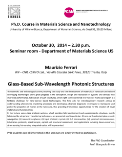
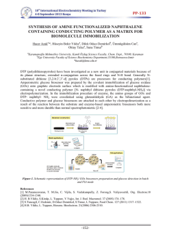
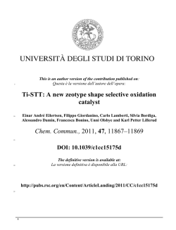
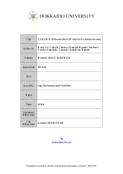
Nanoscale
REVIEW
Cite this: Nanoscale, 2016, 8, 6921
Nanostructured conducting polymers for energy
applications: towards a sustainable platform
Srabanti Ghosh,*a Thandavarayan Maiyalaganb and Rajendra N. Basu*a
Recently, there has been tremendous progress in the field of nanodimensional conducting polymers with
the objective of tuning the intrinsic properties of the polymer and the potential to be efficient, biocompatible, inexpensive, and solution processable. Compared with bulk conducting polymers, conducting
polymer nanostructures possess a high electrical conductivity, large surface area, short path length for
ion transport and superior electrochemical activity which make them suitable for energy storage and conversion applications. The current status of polymer nanostructure fabrication and characterization is
reviewed in detail. The present review includes syntheses, a deeper understanding of the principles underlying the electronic behavior of size and shape tunable polymer nanostructures, characterization tools
Received 11th December 2015,
Accepted 24th February 2016
and analysis of composites. Finally, a detailed discussion of their effectiveness and perspectives in energy
DOI: 10.1039/c5nr08803h
storage and solar light harvesting is presented. In brief, a broad overview on the synthesis and possible
applications of conducting polymer nanostructures in energy domains such as fuel cells, photocatalysis,
www.rsc.org/nanoscale
supercapacitors and rechargeable batteries is described.
1.
Introduction
The concept of conducting polymers (CPs) emerged in recent
decades and continues to attract the scientific community.1,2
Research in this area is continuing to grow with the objective
of tuning the intrinsic properties of nanodimensional CPs to
offer multiple functionalities. Hence, primarily driven by the
opportunity to develop novel multifunctional materials on one
hand, and sustainable technologies on the other, several successful approaches have been explored to develop conducting
polymer nanostructures (CPNs). Many excellent reviews regarding the development of CPs such as polyaniline, polymer film
electrodes and their characterization have been published.3–7
Moreover, the sensing and device applications of CPs have also
been reviewed.8–11 However, the preparation, characterization
and application of CPNs in the energy domain are still at the
foreground of research activity.12–14 Consequently, there is a
need for a deeper understanding of the availability of novel
polymer nanostructures, the development of models of the
materials’ behavior and technologies aimed at optimizing and
implementing their active function in applications. Specifically, we present an overview of the different methods commonly employed in the fabrication of CPNs and hybrid
composites. We also discuss the characterization of CPNs
a
CSIR - Central Glass and Ceramic Research Institute, 196, Raja S.C. Mullick Road,
Kolkata-700032, India. E-mail: [email protected], [email protected]
b
School of Chemistry, University of East Anglia, Norwich NR4 7TJ, UK
This journal is © The Royal Society of Chemistry 2016
using microscopy and other techniques as well as their application in the fields of energy storage and conversion, and
electrocatalysis.
The initial work on CPs was instigated by three Nobel laureates (A. J. Heeger, H. Shirakawa, and A. G. MacDiarmid).15,16
They discovered an increase of nearly 10 orders of magnitude
in the electrical conductivity of polyacetylene (PA) when it was
doped with iodine or other acceptors.17 As shown in Fig. 1,
conducting polymers include polyacetylene (PA), polypyrrole
(PPy), polyaniline (PANI), poly(3,4-ethylenedioxythiophene)
(PEDOT) and poly( p-phenylenevinylene) (PPV) etc. Since then,
CPs have received increasing attention in both fundamental
research and various application fields in recent decades.
Compared to bulk polymers, CPNs displayed superior performances for energy storage and conversion which is associated with the nanoscale size giving a superior electrical
conductivity, high surface area, high carrier mobility, improved
electrochemical activity and good mechanical properties etc.
Numerous synthetic strategies have been developed to obtain
various conductive polymer nanostructures such as nanoparticles (NPs), nanowires, nanofibers, and nanotubes etc.,
and high-performance devices based on these nanostructured
polymers have been realized.12–14
This review covers recent progress in the wet-chemical
development of conducting polymer nanostructures and
hybrid strategies based on the functional associations of semiconductors and metals via template synthesis routes, including soft and hard template methods. Controlling the
dimensions of each component permits engineering of the
Nanoscale, 2016, 8, 6921–6947 | 6921
Review
Fig. 1
Nanoscale
Molecular structure of some representative conducting polymers.
electronic energy state within the nanoscale architecture,
which makes conducting polymers very useful for energy applications, such as photovoltaics, catalysis, solar energy harvesting, fuel cells, batteries and electrochemical supercapacitors
etc. This review highlights the current status of the representative applications of CPNs as active electrode materials for
energy conversion and energy storage applications with a
strong emphasis on recent literature examples. Finally, this
review ends with a summary and some perspectives on
the challenges and opportunities in this emerging area of
research.
2. Synthesis
Conventionally, CPs have been synthesized via the chemical or
electrochemical oxidation of monomers, followed by coupling
of the charged monomers to produce the polymer chains,
which is the simplest system. However, CPNs have been fabricated with the help of templates during the polymerization
process. This section covers two main approaches for the controlled synthesis of CPNs and CP based hybrid nanocomposites as well as heterostructures, which are the template-based
synthesis and the template-free synthesis. The template-based
synthesis is the most commonly used for producing
morphology and size tunable nanostructures which are
6922 | Nanoscale, 2016, 8, 6921–6947
expected to be the most important for device applications. As a
result, there has been a considerable improvement in the
large-scale production of CPNs in recent years with different
approaches, such as the conventional hard-template method,
soft-template method and template-free synthesis etc.18–20
2.1.
Template-based synthesis
The template-based synthesis of polymer nanostructures is
particularly discussed and concluded to be one of the efficient
strategies for synthesizing various CPNs with control of the
morphology and size.
2.1.1. Conventional hard-template method. The hard template route has been identified as the most common technique
for the synthesis of CPNs, employing templates such as tracketch polycarbonate (PC) or polyester (PE) membranes and
anodic aluminum oxide (AAO) membranes.21–23 Additionally,
other solid porous materials, such as zeolites,24 silica-based
mesoporous molecular sieves,25 oxides,26 polyoxometallates,27
and synthesized nanostructures28 can be used in the hard template synthesis of CPNs.29 The polycarbonate PTM (PC-PTM)
and the AAO membranes were applied for both the chemical
and electrochemical synthesis of a wide range of controllable
nanorods, nanofibers, and nanotubes of CPs such as PEDOT,30
PANI,31 PPy,32,33 P3HT,34 PPV etc.35 This was first developed by
Martin and became a widely used method with high controll-
This journal is © The Royal Society of Chemistry 2016
Nanoscale
ability for producing nanowires or tube nanostructures.
Furthermore, the dimensions of the deposited nanostructures
can be easily controlled by regulating the template pores and
deposition conditions. Using non-connected AAO porous
membranes as a template, the synthesis of the CP happened
inside the isolated pores, replicating the shape of the void
space in the templates and consequently, aligned 1D nanotube and nanowire structures are usually achieved after removing the template scaffold (Fig. 2a). Liu et al. reported the
formation of coaxial nanowires within the 200 nm diameter
pores of an AAO template as a result of the simultaneous
growth of core MnO2 and shell PEDOT by electrochemical
deposition (Fig. 2b).36 On the other hand, the nanowire or
nanotube arrays fabricated from mesoporous silica are interconnected by small pillars formed in the micro- or mesopores
of the silica pore walls. Bein et al. prepared conducting
filaments of PANI in the 3 nm wide hexagonal channel of the
aluminosilicate MCM-41.37 There is another hard template,
namely, a reactive template that has potential for the synthesis
of CPs of different sizes and shapes. The method is a simple,
one-step procedure, based on redox reactions using inorganic
nanostructures, such as the V2O5 fibers or MnO2 nanowires.
Review
Manohar et al. described the chemical oxidative synthesis of
bulk quantities of micron long, 100–180 nm diameter nanofibers of electrically conducting PEDOT in the form of powders
using a V2O5 nanofiber seed template.38 Pan et al. developed a
reactive template strategy by using manganese oxide nanowires
for the synthesis of PANI nanotubes.39 Lu et al. synthesized
PPy nanotubes by using the complex of FeCl3 and methyl
orange which can initiate the polymerization of PPy monomers
and direct the growth of PPy into nanotubes.40 Moreover,
Li et al. obtained one-dimensional V2O5/PANI core–shell nanobelts by using a V2O5 nanobelt as a reactive template.41
However, the majority of these approaches involve multi-step
synthetic routes to pre-modify the core templates, and to
remove the template by either heating, or chemical treatment.
The overall process is tedious and not suitable for large-scale
production. Additionally, the subsequent removal of the template may result in the deformation of the as-prepared CPNs.
In comparison to hard templates, the soft template approach
is relatively straightforward.
2.1.2. Soft-template method. The soft-template approach
is a relatively simple fabrication process that includes micro-/
mini-emulsion polymerization, reversed-microemulsion, layer-
Fig. 2 (a) Image courtsey of Ran Liu’s personal webpage, Penn State Department of Chemistry. (b) Growth mechanisms of heterogeneous nanostructured MnO2/PEDOT by coelectrodeposition of MnO2 and PEDOT on ring-shaped and flat-top electrodes. Reproduced, with permission, from
ref.36, American Chemical Society. (c) Schematic of the mechanism of the soft-template synthesis of different conducting polymer nanostructures:
(i) micelles acting as soft-templates in the formation of nanotubes. Micelles were formed by the self-assembly of dopants, and the polymerization
was carried out on the surface of the micelles; (ii) nanowires formed by protection of the dopants. The polymerizations were carried out inside the
micelles; (iii) monomer droplets acting as soft-templates in the formation of micro-spheres; and (iv) polymerization on the substrate producing
aligned nanowire arrays. Nanowires were protected by the dopants, and polymerization preferentially occurred on the tips of the nanowires. Reproduced, with permission, from ref. 48, Elsevier Ltd. (d) Schematic representation of the electrochemical polymerization of liquid crystalline EDOT–
PDPPA. Reproduced, with permission, from ref. 64, American Chemical Society. (e) HAADF-STEM image of stepwise electropolymerization for the
fabrication of longitudinally integrated conducting polymer nanowires of PEDOT–PPy segmented nanowires in the PEO114-b-PMA(Az)67 template.
Reproduced, with permission, from ref. 65, American Chemical Society. (f ) Depiction of peptide amphiphile (PA) self-assembly in the presence of
EDOT monomers. The self-assembly yields nanostructures with hydrophobic cores that sequester the organic monomer from aqueous solution.
Confined oxidative polymerization of EDOT once partitioned should occur predominately within these hydrophobic regions, resulting in encapsulated conductive polymers. Reproduced, with permission, from ref. 66, Wiley-VCH.
This journal is © The Royal Society of Chemistry 2016
Nanoscale, 2016, 8, 6921–6947 | 6923
Review
by-layer self-assembly and block copolymer mediated fabrication etc.42–47 The soft-template method based on the selfassembly of surfactants is typically employed for the synthesis
of shape-controlled CPNs as shown in Fig. 2c.48–50 Wan et al.
discovered that PANI nanowires could be synthesized by in situ
doping polymerization in the presence of β-naphthalene sulfonic acid (β-NSA) as the dopant without the need of any membrane.51 Zhang et al. reported various PPy nanostructures in
the presence of various anionic, cationic, or non-ionic surfactants with various oxidizing agents.52 In the emulsion
polymerization route, the shape and dimensions of the CPNs
are highly dependent on their micellar state, either in the isolated or in the aggregated state. Jayakannan et al. obtained a
coral-like morphology of PPy nanospheres in the presence of
aggregated templates at a higher surfactant concentration,
whereas at a lower surfactant concentration the weakly aggregated micelles produced well-defined PPy nanospheres of
150–800 nm.53
Shinkai et al. reported the preparation of a porphyrin-based
1D assembly by linking the porphyrin units using the polymerization of butadiyne in the gel state.54 Morin et al. recently
reported the synthesis of conjugated nanowires prepared by
the topochemical polymerization of butadiynes in the xerogel
state.55 Li et al. developed an in situ sacrificial oxidative template route for the bulk synthesis of two-dimensional nanorings and flat hollow capsules of PANI nanostructures.56
Manohar and co-workers reported the synthesis of clip-like
nanostructures of PPy, PANI, and PEDOT using an anionic
oxidant/cationic surfactant complex as a template.57 The judicious combination of the main parameters, such as the surfactants, oxidizing/doping agents, pH, temperature, and other
structure-directing agents, provides infinite possibilities for
fabricating nanostructures with desirable morphologies.
A self-organized template, lyotropic liquid crystal (LC) with
mesophases (hexagonal or lamellar phases) was utilized for the
synthesis of anisotropic conducting polymer nanostructures
which cannot be achieved using traditional bulk or solution
polymerizations.58,59 Hulvat et al. developed a new method for
the fabrication of hexagonally ordered fibrillar PEDOT nanostructures in hexagonal LC using the electropolymerization
technique.60,61 Remita and co-workers developed swollen hexagonal mesophases composed of oil-swollen tubes with tunable
diameters, which are stabilized by a monolayer of surfactant
and cosurfactant molecules, that have been used to effectively
control the morphology and the size of the nanostructures.62
Ghosh et al. reported a single-step preparation of PEDOT nanostructures with spindle-like or vesicle-like shapes in the hydrophobic domains of hexagonal mesophases via chemical
oxidative polymerization of EDOT monomers using FeCl3 as
the oxidizing agent.63 Ghosh et al. also reported the controlled
synthesis of micrometer long nanofibers of conducting poly
(diphenylbutadiyne) (PDPB) nanofibers that were synthesized
in the oil tubes of the hexagonal mesophases by photoinduced radical polymerization using a chemical initiator or
by gamma irradiation. The diameter of the nanofibers can be
varied from 5 to 25 nm in a controlled fashion, and is directly
6924 | Nanoscale, 2016, 8, 6921–6947
Nanoscale
determined by the diameter of the oil tube of the doped mesophases, thus proving a direct templating effect of the mesophase. Moreover, controlling the liquid-crystalline phase,
depending on the composition which ranges from columnar
to lamellar or cubic phases, can direct the dimensionality and
the morphology of the nanoobjects grown in situ as shown in
Fig. 2d.64 Komiyama et al. also developed a block-copolymertemplated (a chemical affinity template) electropolymerization
technique in order to form PPy and thiophene derivative based
CPNs (Fig. 2e).65 Stupp and coworkers described methods to
chemically and electrochemically synthesize CPs within bioactive aqueous gel matrices formed by a peptide amphiphile.66,67 Fig. 2f illustrates the formation of a hydrophobic
lipid environment due to the self-assembly of the peptide
amphiphile into cylindrical nanostructures, providing a reservoir for the uptake of the hydrophobic EDOT monomer, which
can consequently be utilized for polymerization in the confined region. Other syntheses through biomolecules are discussed by Kumar et al. and Niu et al.68,69 DNA molecules
provide attractive soft templates for the controlled fabrication
of CPNs.70 Hassanien et al. described the preparation of DNAtemplated polyindole nanowires, Moon et al. reported the formation of highly uniform conductive PPy nanowires with a
DNA template and Ma et al. discussed the preparation of PANI
nanowires on Si surfaces fabricated with DNA templates.71–73
Richardson-Burns et al. developed a polymerization of PEDOT
around living cells and described a neural cell-templated CP
coating for microelectrodes and a hybrid conducting polymer–
live neural cell electrode.74 Pomposo et al. also reported the
enzymatic synthesis of PEDOT nanostructures.75 Niu et al.
described the synthesis of one-dimensional composite nanofibers via the head-to-tail assembly of the tobacco mosaic virus
(TMV) as well as in situ polymerization of PANI on the surface
of the TMV.76 Other templates can serve as both the oxidant
and sacrificial template for the chemical oxidative polymerization, e.g., Pahovnik et al. described the synthesis of PANI
nanostructures using ionic liquids as soft templates and
Li et al. reported PANI nanorings and flat hollow capsules synthesized by in situ sacrificial oxidative templates using a V2O5/
H2O2/H3PO4 mixture.77,78 It is important to note that subtle
changes in the polymerization parameters often result in
drastic differences in the morphology of the resulting CPNs.
Zhu et al. developed the synthesis of rambutan-like hollow
spheres of PANI by a self-assembly method in the presence of
perfluorooctane sulfonic acid (PFOSA), which served as the
dopant and soft template, and induced superhydrophobicity at
the same time.79 Park et al. developed a technique for the
anisotropic growth control of PANI nanostructures, specifically
nanospheres, nanorods, and nanofibers by employing a polymeric stabilizer, poly(N-vinylpyrrolidone). The polymerization
rate became slower in the presence of the stabilizer (the rate
constants calculated at the initial stage decreased with increasing concentration of the stabilizer), yielding PANI nanostructures with lower aspect ratios, and the stabilizer sterically
restricted the directional fiber growth mechanism governing
PANI chain growth in aqueous solution.80
This journal is © The Royal Society of Chemistry 2016
Nanoscale
2.2.
Template-free synthesis
The template-free method is considered to be a simple,
straightforward and cost effective technique for the synthesis
of CPNs without the need of a template or post-treatment for
template removal.81,82 Additionally, uniform nanostructures
are formed, which are easily scalable and reproducible. Template-free synthetic strategies such as interfacial polymerization (self-assembly), electrospinning and radiolysis are briefly
discussed. Various CPNs such as nanotubes, nanofibers,
hollow spheres, etc. were successfully synthesized by the
template-free method. Typically, PANI with one dimensional
(1D) morphology in aqueous solution has been intensively
investigated to fabricate 1D PANI nano structures in the
absence of templates.83 Dind et al. and Park et al. reported a
one-pot surfactant-free route to synthesize PANI hollow nanospheres using controllable incontinuous nanocavities.84,85
Furthermore, an oriented nanowire was also prepared through
controlled nucleation and growth during a stepwise electrochemical deposition process without using any structure controlling agent.86 Tseng et al. developed a site-specific
electrochemical method for the fabrication of individually
addressable PPy, PANI and PEDOT nanowires on microelectrode junctions.87 Similarly, Ramanathan et al. created arrays
of individually addressable CP nanowires of controlled dimensions and high aspect ratios with site-specific positioning,
alignment and chemical compositions.88 Up to now, a range
of PANI nanostructures such as nanotubes,89,90 nanowires
or fibers,91,92 have been prepared by the template-free method.
2.2.1. Self-assembly or interfacial polymerization. The
interfacial polymerization (IP) technique is useful for synthesizing CPNs via oxidative coupling processes at low temperatures and with limited side reactions, and can avoid the use of
catalysts or phase transfer agents. This involves step polymerization of two reactive monomers or agents, which are dissolved,
respectively, in two immiscible phases and the reaction takes
place at the interface of the two liquids. Interestingly, mass
and charge diffusion through a liquid–liquid interface control
the crystallinity, size and shape of CPNs.93–96 Huang et al.
used an aqueous–organic interfacial polymerization method
for the synthesis of high quality PANI nanofibers having diameters of 30–50 nm under ambient conditions.97 Haldorai et al.
described IP as a reliable non-template approach with an easy
synthesis and economic viability for synthesizing poly(anilineco-p-phenylenediamine) [ poly(Ani-co-p-PD)] nanorods via a
microwave-assisted aqueous–ionic liquid interfacial oxidative
polymerization in the presence of acid dopants.98 Du et al.
have reported the formation of PANI nanotubes under various
synthesis conditions without templates.99 Nuraje et al. also
described the interfacial crystallization of conductive polymers
at the liquid–liquid interface, allowing PANI and PPy polymers
to form single crystalline nanocrystals in a rice-like shape in
the dimensions of 63 nm × 12 nm for PANI and 70 nm ×
20 nm for PPy.100,101 Ma et al. reported unique aligned
PANI belts doped with dodecatungstosilic acid (H4SiW12O40)
that were synthesized by the interfacial control method
This journal is © The Royal Society of Chemistry 2016
Review
which demonstrated a superior performance in the
conductivity.102
2.2.2. Electrospinning. Electrospinning is one of the most
efficient techniques to create continuous and aligned conducting polymer nanofibers and composites under a high electric
field.103 Electrospinning occurs with the development of a jet
when the repulsion forces of a charged solution overcome the
surface tension of the solution under a high electrostatic field.
Finally, the spun fibers are deposited commonly as a nonwoven web on a collector. MacDiarmid et al. reported the fabrication of PANI nanowires with sub-100 nm diameters doped
with DL-camphorsulfonic acid.104 Chronakis et al. reported
electrospun PPy/PEO nanofibers with diameters in the rage of
about 70–300 nm with improved electrical conductivity and
Choi et al. reported a method of fabricating electrospun
PEDOT:poly(styrenesulfonate) (PSS)/PVP nanofibers.105,106
Feng et al. also reported the fabrication of aligned PEDOT
fibers and tubes based on electrospinning and oxidative
chemical polymerization.107 The electrospinning process
appears to be the single method that can produce continuous
long nanofibers; however, in order to assist in the fiber formation, non-conducting polymers or supports are usually
added which lower the conductivity of the electrospun composite fibers.
2.2.3. Radiolysis. Alternatively, γ-irradiation has been used
extensively to generate nanostructured materials under
ambient temperature and pressure.108,109 In comparison to
other methods, some of the advantages of the radiation
initiated polymerization over conventional methods are: (i) the
absence of foreign matter, such as the initiator, catalyst, etc.;
(ii) polymerization at room temperature or in the solid state;
(iii) the rate of the initiation step can easily be controlled by
varying the dose rate; and (iv) the initiating radicals can be
produced uniformly by γ-irradiation. Pillalamarri et al. developed the radiolytic synthesis of PANI nanofibers with diameters
of 50–100 nm and lengths of 1–3 μm as well as nanorods
with typical lengths between 5 and 10 μm and diameters of
250–500 nm.110 Karim et al. also reported the synthesis
of highly uniform conducting PPy with particle sizes of
100–500 nm by an in situ gamma radiation (60Co γ-ray)induced chemical oxidative polymerization method.111 Huang
et al. developed an one pot method for polyaniline/silver composites under γ-irradiation which revealed that the PANI nanofibers were formed by the reaction of aniline cation radicals
formed by the reaction of the aniline cation and •OH, and the
Ag NPs were formed by the reaction of Ag+ and e−aq.112
Recently Remita’s group reported a series of radiolytic syntheses of PEDOT nanostructures and also studied the mechanism in detail. Lattach et al. developed self-assembled
hydrophilic PEDOT nanostructures via an oxidation process
initiated by HO• radicals produced by water radiolysis without
using chemical initiators.113 In continuation of that work, a
detailed study of the effect of oxidizing agents on radiolytic
PEDOT polymerization has been reported by Remita and coworkers. Interestingly, HO• radicals led to PEDOT–OH globular
nanostructures with hydrophilic properties and N3• radicals
Nanoscale, 2016, 8, 6921–6947 | 6925
Review
enabled the formation of amphiphilic PEDOT–N• fibrillar
nanostructures.114 Cui et al. reported the radiation-induced
reduction (action of e−aq under a N2 atmosphere) polymerization route for the synthesis of PEDOT nanostructures.115 Cui
et al. also reported the template free synthesis of spherical PPy
NPs using a radiolytic method as a novel approach.116 Coletta
et al. also reported a new alternative method based on electron
beam irradiation for the synthesis and detailed mechanistic
studies of PEDOT nanostructures using time-resolved absorption spectroscopy coupled with pulsed radiolysis.117 This “fast”
technique offers several advantages: it enables, via the pulsed
electron accelerator, (i) the generation of oxidizing species in
the aqueous irradiated medium in a very short time, (ii) quantitative knowledge of the concentration of the oxidizing
species, (iii) the appearance and disappearance of the transient species produced during EDOT oxidation to be followed in
real-time by absorption spectroscopy and the estimation of the
rate constants of the involved consecutive reactions. By combining the experimental and theoretical study it was demonstrated that, in air and under a N2O atmosphere, HO•-induced
oxidation of EDOT implies the formation of a transient
species, namely an EDOT•+ cation radical, which dimerizes
and deprotonates leading to a stable product, namely an
EDOT2 dimer. This result proves that PEDOTox growth is not a
chain reaction. On the contrary, it proceeds through a step-bystep mechanism made up of the following recurrent steps: oxidation/activation, a growth/chain length increase and deprotonation. The quantitative synthesis of PEDOTred polymers
throughout a reduction–polymerization process also implies a
step-by-step mechanism and requires the use of two hydrated
electrons per EDOT molecule.
2.3.
Conducting polymer hydrogels
Hydrogels are polymeric networks that have a high level of
hydration and three-dimensional (3D) microstructures and can
be made electrically conductive by embedding various CPs
which combine the unique properties of hydrogels with the
electrical and optical properties of semiconductors.118–121
Conducting polymer hydrogels (CPHs) are a class of unique
materials that synergize the advantages of conducting polymers and polymer hydrogels. The CPHs have hierarchically
porous nanostructures crosslinked in a three-dimensional (3D)
way, which afford their stable mechanical, unique chemical
and physical, and outstanding electrochemical properties for
potential use in electrochemical applications, including longterm energy storage devices, lithium-ion battery (LIB) electrodes, electrochemical capacitors (ECs), biofuel cells, printable
electronic devices, and biosensors.122–126 Different CPs such as
PEDOT, PANI, PPy and PTh can be used as the electrical backbone of the material.127–131 A PANI hydrogel free of insulating
polymers has been synthesized by using phytic acid as both
the gelator and the dopant to directly form a gel network,132
an amphiphilic thiophene derivative hydrogel with unusual
two dimensional building blocks has been synthesized in one
step via a combination of oxidative coupling polymerization
and non-covalent crosslinking133 and a PPy nanotube hydrogel
6926 | Nanoscale, 2016, 8, 6921–6947
Nanoscale
with controlled morphology has been synthesized by oxidative
polymerization in the presence of dye molecules as templates.134 Other interesting CP based materials, aerogels, are a
novel class of highly porous nanomaterials that have unique
physicochemical properties such as ultra-low density, large
specific area, disordered open pores, elaborate 3D networks,
etc.135,136 Zhang and co-workers reported a series of CP aerogels based on PEDOT/poly(styrenesulfonate) (PSS); however,
the existence of the required non-conducting PSS would significantly limit the application of PEDOT/PSS aerogels.137,138
However, they developed a new method based on an emulsion
template for the synthesis of CP aerogels by supercritical
drying or freeze drying of the as-synthesized PEDOT-S/PEDOT
hydrogels with superior adsorption capacity and enhanced
electrochemical capacitance as shown in Fig. 3a.139 Fig. 3a–f
show that the waterborne EDOT derivative, sodium 4-(2,3-dihydrothieno[3,4-b][1,4]dioxin-2-yl)-methoxy-butane-1-sulfonate
(EDOT-S), serves as a reactive surfactant to disperse and stabilize the hardly soluble EDOT to form a stable emulsion. The
resulting emulsion, acting as a sol, was converted into a hydrogel by triggering the oxidative coupling polymerization of both
EDOT-S and EDOT with the oxidizing agent. After using supercritical CO2 or freeze drying the resulting hydrogel precursor,
the PEDOT-S/PEDOT aerogel was obtained successfully.
A typical SEM image, as shown in Fig. 3g, indicates that the
resulting aerogel is rich in hierarchical pores of 2–50 nm and
these macropores are randomly self-assembled by the interconnected sphere-like nanostructures. There is a huge challenge
to make CP hydrogels elastic due to the inherent rigidity of the
conjugated macromolecular chains resulting from the delocalized p-electron system. Recently, Lu et al. reported the preparation of elastic, conductive, PPy hydrogels and sponges.140
The PPy hydrogel could be compressed by ≥70% and return to
its original shape in 30 seconds as shown in Fig. 3h–j. From
the compressive stress versus strain curves for the PPy hydrogels along the loading direction during loading–unloading
cycles at ε = 10–70%, the compressive stress returned to the
origin after unloading for each strain ε (Fig. 3k).
2.4.
Conducting polymer based composites
Polymer nanocomposites have attracted considerable research
interest due to their unique physicochemical properties that
cannot be obtained with the individual components, and their
potential for versatile applications ranging from environmental remediation, energy storage and novel catalysts to biomedical applications etc.141–143 CP based composite materials
are also gaining importance due to their synergistic and
hybrid properties derived from several components.144 Composites of noble metals and CPs exhibit many excellent properties
because of the combination of different functional components in a single unit. It has been reported that CPs are
usually employed as a supporting matrix to incorporate noble
metal NPs for catalytic applications.145–148 Zhang et al. developed highly dispersed composite gold core/polythiophene shell
NPs with the potential for electronic device applications.149
Shi et al. simply synthesized Au–PEDOT core–shell nanocables
This journal is © The Royal Society of Chemistry 2016
Nanoscale
Review
Fig. 3 Emulsion-template strategy for the synthesis of conducting polymer aerogels: (a) digital photos of the EDOT-S stabilized EDOT emulsion,
(b) PEDOT-S/PEDOT hydrogel and (c) PEDOT-S/PEDOT aerogel and schematic diagrams of the (d) EDOT-S stabilized EDOT emulsion, (e) PEDOTS/PEDOT hydrogel and (f ) PEDOT-S/PEDOT aerogel. (g) SEM image of supercritical CO2 dried PEDOT-S/PEDOT aerogel. Panels (a)–(g) are reproduced, with permission, from ref. 139, the Royal Society of Chemistry. (h–j) Elasticity of PPy hydrogel. Macroscopic visualization, showing that the
PPy hydrogels recover their original shape after compression ≥70%. (k) σ versus ε curves for PPy hydrogels along the loading direction during
loading–unloading cycles at ε = 10–70%. Digital photos showing the fast removal of (l and m) methyl orange, (n) victoria blue and (o) brilliant yellow
from wastewater with the elastic PPy hydrogels in syringes. Panels (h)–(o) are reproduced, with permission, from ref. 140, Nature Publishers.
by the one-step interfacial polymerization of EDOT (in the
organic phase) and HAuCl4 (in the aqueous phase).150 Chang
et al. also conducted the synthesis of Ag–PPy core–shell NPs
with an average core diameter of 36 nm and a shell thickness
of 13 nm via a simple one-pot synthesis,151 O’Mullane et al.
prepared PANI–Pt nanocomposites by the spontaneous
reduction of K2PtCl4 with PANI that can be further processed
into thin films that show electrocatalytic properties in both
acidic and neutral aqueous media.152 Gao et al. also reported
the even distribution of Pd nanostructures deposited on PANI
surfaces through an in situ reduction of Pd(NO3)2 by PANI.153
Shih et al. showed that the morphologies of Pt nanostructures
deposited on PANI surfaces largely depend on the doping state
This journal is © The Royal Society of Chemistry 2016
of the membranes; Pt aggregates that are assembled from
smaller NPs are formed on doped PANI membranes while, in
contrast, sheet-like Pt structures are deposited on undoped
PANI membranes.154 These bottom-up approaches offer an
efficient and simple route for the fabrication of nanostructured metal/conducting polymer composites. Interestingly,
metal NPs supported on CPs have shown enhanced catalytic
performances due to the effective surface areas and the synergistic coupling effect between the two components. Yang et al.
reported a soft-template method that allows the one-pot
synthesis of ring-like PPy/Pd nanocomposites via the redox
reaction between PdBr42− and the Py monomer as shown
in Fig. 4.
Nanoscale, 2016, 8, 6921–6947 | 6927
Review
Nanoscale
Fig. 4 TEM image of PPy/Pd composite nanorings. Schematic diagram of the fabrication of PPy/Pd composite nanorings. Reproduced, with permission, from ref. 146, Royal Society of Chemistry.
The probable mechanism of formation of composite nanorings is proposed as shown in Fig. 4. An insoluble complex of
(CTA)2PdBr4 formed between a noble metal compound,
sodium tetrachloropalladate, and a cationic surfactant, cetyltrimethylammonium bromide (CTAB), with lamellar mesostructures was used as a template and the composite nanorings
were synthesized via the redox reaction between PdBr42− and
the monomer. After complete polymerization, PPy/Pd composite nanorings were formed. Moreover, these nanocomposites
have shown a wide range of tailor-made applications. Platinum
NPs have been incorporated into a PANI matrix resulting in a
composite that is useful for the electrochemical process of
hydrogen evolution.155 An original ‘second-order-template’
method has been proposed for the fabrication of Ni and PANI
nanotube composite nanowires within the pores of an
alumina template, and then nickel nanowires were deposited
into these nanotubules.156 Drury et al. also studied the fabrication and characterization of silver/PANI composite nanowires
in porous anodic alumina.157 Gold NP based CP composites
can be used as substrates for surface enhanced Raman scattering.158,159 Palladium, gold and platinum NP based CP nanocomposites illustrated superior catalytic activity,160–165 and
biosensing,166–170 therapeutic,171,172 and water treatment
applications.173 Moreover, incorporating semiconductor nanocrystals into CPs can complement the visible light absorption
range of the polymers as well as allow sensitizing or immobilization of the semiconductor nanocrystals for renewable
energy applications such as heterojunction-type photovoltaics
and photocatalysis.174–176 A significant effort has been devoted
to create heterojunction materials that contain a conducting
polymer layer as well as an inorganic layer. It is challenging
to design heterostructures with the appropriate morphologyrelated orientation and band position of each semiconductor
and polymer unit within the heterostructure. Appropriate band
gap alignment in combination with easy solution-processability makes this material a promising candidate for energy
harvesting applications. Here, we discuss the synthesis and
6928 | Nanoscale, 2016, 8, 6921–6947
characterization of the unique heterojunction between conjugated polymers and semiconductor NPs. For example, PDPB
nanofibers were coupled with ZnO NPs and the photocurrent
response to visible light and photocatalysis applications along
with other conjugated polymer based heterojunctions has
been summarized.177–180
3. Characterization
The characterization of CPNs is closely tied to the synthetic
technique. Electron microscopy, optical spectroscopy and
scattering techniques are widely used. Scanning electron
microscopy (SEM) continues to provide valuable information
about the morphology of polymer nanostructures and composite materials. A wide variety of complimentary methods are
also available, including atomic force microscopy (AFM), transmission electron microscopy (TEM) and cryo-TEM etc. As these
methods continue to improve, it will be possible to have a
more complete understanding of the relationship between the
polymer nanostructure and their macroscopic properties, for
example, through infrared absorption using a combined technique, namely, AFMIR. The use of cyclic voltammetry for
studying the electronic states of CPs is also promising and
electrochemical impedance spectroscopy can be used to study
the energy storage and dissipation properties of CPs, which is
reviewed in detail.181 The electrical conductivity of the polymer
films can be measured using a Kelvin four-point probe
technique. In this section, the latest advancements in the
characterization of CP-based functional nanomaterials for
sustainable development in energy conversion and storage are
reviewed.
3.1.
Advanced characterization techniques (AFM and AFMIR)
Atomic force microscopy has been extensively used to investigate the surface morphology, roughness, phase segregation,
packing of the polymer chains and conformation and
This journal is © The Royal Society of Chemistry 2016
Nanoscale
mapping the distribution of the electric charges etc. of conducting polymers. Taranekar et al.182 studied the formation of
unique ‘nanoscale’ morphologies due to phase-segregation of
polysiloxane domains and cross-linked PPy from the AFM
images. Pruneanu et al.183 studied the self-assembly of DNAtemplate PPy nanowires using the noncontact mode. Another
widely used application of dynamic modes using electrical
force microscopy (EFM) provides the possibility of probing the
localized charge distribution, surface potential, and doping
profiles at the surface.184,185 Takami et al. measured the conductivity of polydiacetylene thin films using double-tip scanning tunneling microscopy.186 Scanning Kelvin probe
microscopy (KPM), which identifies the local surface potential,
offers the possibility of distinguishing between regions with
different chemical natures or compositions.187 For example,
Semenikhin et al.188 studied the evidence of local structural
inhomogeneity and non-uniform dopant distribution in conducting polybithiophene (PBT) and the origin and characterization of the structural inhomogeneity and local potential
Review
distribution of CP have been studied by other groups using
KFM.189 Significant progress has been reported in the AFM
characterization of CPNs. Tseng et al. reported the electrical
bistability of PANI nanofiber/gold NPs using a conductive
atomic force microscope.190 For example, in a previous study
developed by Kobayashi et al. single NPs of poly(2-methoxy-5(2-ethylhexyloxy)-1,4 phenylenevinylene) (MEH-PPV) have been
characterized using simultaneous atomic force microscopy
(AFM) and fluorescence microspectroscopy.191 The tip of the
AFM probe is used to apply local pressure to individual CP
NPs and the fluorescence microscope is simultaneously monitoring changes in the fluorescence spectral shifts and emission intensities. The two force curve–intensity traces that
result as a function of time are shown in Fig. 5a and more
than 70% of all particles showed an increase of fluorescence
intensity. The emitted light intensity was spectrally separated
into blue and red components Iblue and Ired, respectively
(Fig. 5b), as detected by two photodetectors, and the NP exhibits a pronounced blue shift at the contact point of the tip
Fig. 5 Simultaneous AFM and fluorescence microscopy study: (a) two examples of simultaneously measured force curve (blue) and fluorescence
intensity (black) traces on single MEH-PPV nanoparticles. (b) Fluorescence spectrum (black) of a MEH-PPV nanoparticle and transmission spectrum
(blue) of a dichroic mirror used to spectrally separate the emission into blue (Iblue) and red (Ired) components. (c) Scheme of the proposed model.
Panels (a)–(c) are reproduced, with permission, from ref. 191, American Chemical Society. (d) Topographic image of PDPB nanofibers by conventional AFM. AFMIR mappings of the photo-induced PDPB polymer nanostructures synthesized in the swollen hexagonal phase measured at different
fixed wavenumbers: 1490 cm−1 (e), 2146 cm−1 (f ) and 3054 cm−1 (g). (h–j) NanoIR spectra recorded at three different spectral regions of the PDPB
polymer. Panels (d)–( j) are reproduced, with permission, from ref. 192, the Royal Society of Chemistry.
This journal is © The Royal Society of Chemistry 2016
Nanoscale, 2016, 8, 6921–6947 | 6929
Review
with the particle surface, which is reversed upon retraction of
the tip. The phenomena are interpreted in terms of the local
disturbance of the MEH-PPV chain conformation by the probe
tip and the contact of the sharp probe tip (with a tip radius of
7 nm) with the particle surface causes local conformational
disruption of the MEH-PPV chains near the tip as shown in
Fig. 5c. Ghosh and co-workers have also been able to directly
observe the polymer regions via AFM topography imaging and
then rapidly acquire high-resolution local chemical spectra at
selected regions on the sample by the AFMIR technique using
a nanoIR instrument with a tunable pulsed laser as the IR
source (Fig. 5d–g and h–j).192 When the sample absorbs the IR
laser pulse, it warms via a photothermal effect, resulting in
a rapid thermal expansion of the absorbing region of the
sample. Consequently, the thermal expansion pulse impacts
the tip of the AFM cantilever and causes it to oscillate. As the
amplitude of oscillations is proportional to the absorption, it
is possible to record local infrared absorption spectra and
make chemical maps by scanning the surface at a given wavelength. The surface topography of the PDPB nanostructures
showed that well dispersed fibers formed during deposition
on the ZnSe substrates as shown in Fig. 5d.
Fig. 5e shows the IR absorption signal measured by the cantilever when the laser is set at 1494 cm−1. The brighter purple
colors indicate regions of stronger IR absorption at this particular wavenumber and the absorption intensity discriminates
the polymer domains which are distinct from the low-intensity
background (green color). The spectral region at 2300–
2000 cm−1 of the triple bond stretching was thoroughly
analyzed and the disappearance of the monomer band at
2146 cm−1 after irradiation demonstrates that the polymerization is complete (Fig. 5g). A strong signal is measured when
the wavenumber is fixed at 3054 cm−1 which originates from
the benzene ring in the PDPB polymer (Fig. 5h). The combination of the nanoscale probe from an atomic force microscope with a tunable IR source provides simultaneous
measurements of the nanoscale morphology along with chemical composition mapping (Fig. 5h–j) and confirms the presence of PDPB polymer nanostructures on the substrate.
3.2. TEM characterization and understanding the
mechanism of formation
Transmission electron microscopy is a useful tool for studying
the formation of CPNs. Liu et al. reported direct imaging of
the in situ electrochemical deposition of PEDOT using TEM
with an electrochemical liquid flow cell. PEDOT deposition
began preferentially at the edge of the glassy carbon anodes
and then oligomers were observed to form near the electrode
surfaces (Fig. 6a).193 As the reaction continued, both the
nucleation of new domains as well as the growth of pre-existing PEDOT deposits was observed (Fig. 6b), leading to systematic increases in film thickness and roughness (Fig. 6c).
Moreover, EDS mapping can be used to confirm the elemental
composition of the deposited thin film. The elemental
mapping results for sulfur, carbon, oxygen (both PEDOT and
counterion) and chlorine (from the counterion) with their
6930 | Nanoscale, 2016, 8, 6921–6947
Nanoscale
expected distribution are shown in the inset of Fig. 6c.193 The
morphology of CPNs in aqueous solution can be observed by
freezing the system at equilibrium through cryo-TEM, without
phase transition and possible aggregation resulting from
drying procedures.194 A series of reports have been published
by Remita and co-workers utilizing cryo-TEM for the
characterization of CPNs.195–197
There is another interesting report on in situ monitoring of
the nucleation of PANI NPs from micelles using nuclear magnetic resonance (NMR).198 Wu et al. studied the nucleation of
polymeric NPs covering the generation of the clusters and the
forthcoming aggregation to the nuclei by in situ 1H NMR
experiments as shown in Fig. 6d. The changes from aniline
tetramers, water (HOD) as well as SDS, have been followed in
order to correlate the signal transitions from each species in
time sequence. A continuous downfield shift is observed for
the HOD peak due to the acceptance of the protons released
during the formation of aniline oligomers, then the resonance
from the bulk water shifts upfield continuously even though
the total shift is only 4.0 Hz as shown in Fig. 6d. Additionally,
a new broad peak at 4.86 ppm, possibly from aniline tetramers, appeared. This suggests the local environment of the
bulk water (4.83 ppm) is enriched with some compounds containing more electron-donating groups, and an extra water
phase has been formed. Based on NMR results, the nucleation
of PANI in the rod-like micelles has been proposed to occur as
shown in Fig. 6e. The tetramers are identified as the actual
nucleation agents in this process and the co-operation of the
tetramer deprotonation and the fusion of the protective SDS
micelles causes the steady nucleation. The nucleation proceeds
with the translocation of the protonated tetramers from the
micelles to the aqueous bulk, deprotonation of the oligomers
to induce the micellar fusion, and intermolecular packing to
form nascent nuclei.
3.3.
Electrochemical characterization
Electrochemical measurements have been used for evaluation
of the position of energy levels and the band gap of the CPs.
Electrochemical techniques are also useful for investigating
the reversibility, stability and rearrangements of the polymer
films deposited on the electrode. Voltammetry measurements
give information regarding redox properties, the oxidation and
reduction potentials. The oxidation corresponds to electron
extraction from the highest occupied molecular orbital,
HOMO, level and can be correlated to the ionization potential,
whereas the reduction potential is associated with electron
affinity and indicates the lowest unoccupied molecular orbital,
LUMO, level.198,199 In cyclic voltammetry (CV), the current is
measured while the voltage is continuously varied (linear
sweep). The input parameters are therefore the initial and
final voltages and the scan rate, while the output parameters
are the voltage values at which the peaks occur and the current
intensities. For some polymers, either anodic or cathodic
signals are not well resolved. In such cases, differential pulse
voltammetry (DPV) and square wave voltammetry (SWV) techniques, where the current is measured before and after each
This journal is © The Royal Society of Chemistry 2016
Nanoscale
Review
Fig. 6 Bright field TEM images of in situ electrochemical deposition of PEDOT: (a) early stage in the process (immediately after initial CV deposition
on the bench) showing the dark PEDOT depositing from an aqueous solution onto a 20 μm wide glassy carbon working electrode (anode) supported
on a thin silicon nitride membrane; (b) later stage in the process (after subsequent constant voltage deposition), showing the increased thickness
and formation of rough protrusions at the edge of the PEDOT film; (c) higher magnification view of the rough edge of the PEDOT film after further
deposition. Inset: EDS elemental mapping after in situ electrochemical deposition of PEDOT: secondary electron image; sulfur (PEDOT); carbon
(PEDOT and glassy carbon working electrode); chlorine ( perchlorate dopant); oxygen (PEDOT and perchlorate dopant). Panels (a)–(c) are reproduced, with permission, from ref. 193, Royal Society of Chemistry. (d) In situ solution 1H NMR spectra monitoring the temporal changes in the
nucleation of polyaniline in 0.10 M SDS at 298.3 K. (e) Schematic representation of the nucleation for polyaniline in SDS rod-like micelles. Panels (d)
and (e) are reproduced from ref. 198, American Chemical Society.
potential step change (staircase voltammetry), can be used.
The combination of electrochemical impedance spectroscopy
(EIS) with CV provides a powerful tool to understand the electrochemical characteristics of CPs, including the double-layer
capacitance, diffusion impedance, determination of the rate
of charge transfer, charge transport processes and solution
resistance.200–202 To develop CPs, including PANI, PPy, PTh
and their derivatives, as electrode materials for specific applications, such as batteries, fuel cells and interfaces, CV can be
used to explore the capacity of the charge transfer density and
the integrated surface area of the CV graph corresponds to the
capacity of the charge transfer through the polymeric film. EIS
allows the investigation of charge and mass transport kinetics
and charging processes taking place within the analyzed
material and at the active interfaces of the system. The generalized transmission line circuit model predicts the relevant
impedance features of CPs in terms of a Nyquist plot203 based
on a mathematical approach. The two semi-circles at the
highest frequencies, induced by the processes at the metal–
polymer and polymer–solution interfaces, are not always
detectable. Often one or even one-half of a semi-circle is
obtained that partially overlaps with another, depending on
This journal is © The Royal Society of Chemistry 2016
the characteristics of the interfacial processes in terms of the
energy (resistance) to overcome at the relevant interface. Moreover, due to non-homogeneous separation surfaces these semicircles are deformed.204 The stability can be checked by the
Kramers–Kronig transformation and the results can be interpreted as an equivalent circuit (EC) model. Self-made fitting
programs can normally be used to construct a quantitative
fitting by adopting the correct electrical circuit; however, the
obtained parameters do not have physical equivalents. Therefore, it is difficult to extract information about the electrode
reaction mechanism.205 The EIS and CV measurements by
Abidian and co-workers showed that PEDOT film and PEDOT
nanotube coatings had a lower impedance and higher charge
capacity density (CCD) than PPy film and PPy nanotube coatings deposited with the same deposition charge density.206,207
Fig. 7a shows the CV graph of a PPy film, a PEDOT film,
PPy nanotubes, and PEDOT nanotubes and the charge-capacity
density (CCD) increased from 0.105 mC cm2 (bare iridium) to
1608.3 mC cm2 for the PPy film, 1845.3 mC cm2 for the PPy
nanotubes, and 2409.4 mC cm2 for the PEDOT nanotubes. The
electrochemical impedance spectra demonstrated that both
the PEDOT film and PEDOT nanotubes had lower impedance
Nanoscale, 2016, 8, 6921–6947 | 6931
Review
Nanoscale
Fig. 7 (a) CV profile of nanostructured conducting polymers at a scan rate of 100 mV s−1, bare iridium (squares), PPy film (stars), PPy nanotubes (triangles), PEDOT film (diamonds), and PEDOT nanotubes (circles). (b) Bode plot of electrochemical impedance spectroscopy over a frequency range
of 1–105 Hz. (c) Phase plot of electrochemical impedance spectroscopy over a frequency range of 1–105 Hz showing that both the uncoated and
coated electrodes were capacitive in the low-frequency range (<10 Hz). Panels (a)–(c) are reproduced, with permission, from ref. 206, Wiley-VCH.
(d) Equivalent circuit model of electrode–CP–electrolyte interface. The circuit elements are: solution resistance (RS), coating capacitance (CC), pore
resistance (Rpore), double layer interface impedance ZCPE, charge transfer resistance Rt, and finite diffusion impedance ZT. Panel (d) is reproduced,
with permission, from ref. 207, Elsevier Ltd.
across the frequency range due to the higher electrical conductivity of PEDOT compared to PPy (Fig. 7b). The phase plot of
the impedance spectroscopy (Fig. 7c) showed that both the
uncoated and coated electrodes were capacitive in the low frequency range (<10 Hz) and suggests that PEDOT nanotubes act
as a capacitive material for frequencies > 1 kHz and as a Faradaic (resistive) material for frequencies < 1 kHz. Fig. 7d shows
a detailed equivalent circuit model of PPy nanotubes comprising a solution resistance RS, a CP coating capacitance CC, a
pore resistance RPore, a double layer interface capacitance CPE,
a charge transfer resistance Rt, and a finite diffusion impedance ZT.
4.
Applications
After obtaining CPs in the nano-dimension with the preferred
morphology, their exceptional electrical, charge transport,
optical and redox electrochemical properties make them suitable candidates for applications in the energy domain. Some
excellent reviews can be found in the literature which summarize the advances in this field.208–210 For example, functional
nanostructured materials can be used as catalysts or catalyst
supports, electrodes in energy conversion and storage applications such as solar light harvesting, fuel cells, solar cells,
lithium batteries, and electrochemical supercapacitors. Repre-
6932 | Nanoscale, 2016, 8, 6921–6947
sentative achievements in the area of energy applications of
CPNs are summarized in detail in this review.
4.1.
Energy conversion device
4.1.1 Fuel cells. Fuel cells are attractive energy conversion
devices, especially for portable applications, that convert
chemical energy directly to electrical energy. At the anode, the
fuel (e.g., hydrogen) is oxidized to produce protons and electrons. The protons travel across a proton conducting medium
or a polymer electrolyte membrane (PEM) which separates the
anode from the cathode in the case of a proton exchange
membrane fuel cell (PEMFC). In current fuel cell technology,
cost, performance and durability issues still remain big challenges. This can directly be related to the material choice and
design. The electrocatalyst is an important key material in fuel
cells. However, the catalyst currently used in PEMFCs is based
on platinum, which suffers from low activity and poor durability. The basic requirement of the electrocatalyst support is
that it should have high electronic conductivity, a large specific
surface area and good electrochemical stability. To address
these issues, CPN based electrocatalysts were developed with
high activity and excellent stability. Dispersion and size distribution of NP catalysts are achieved on CPNs for maximum
exploitation and fast kinetics which tend to provide a way to
decrease the catalyst loading.211–213 Ghosh et al. showed that,
This journal is © The Royal Society of Chemistry 2016
Nanoscale
in comparison to their bulk counterparts, CP nanostructure
supported catalytic materials can display improved electrode
activities for ethanol oxidation which can be useful for direct
ethanol fuel cells (DFFCs).213 A series of Pt NP based electrocatalysts supported on CPs have been used for the electrocatalytic oxidation of methanol. The electrocatalytic activity of
the CPNs must be greater than that of the corresponding bulk
polymer because of the smaller specific surface area in the
latter case. The effects of electrocatalysts on the performance
of DMFCs have been extensively studied, and CP, PPy, PANI,
poly(3-methylthiophene) and poly(o-phenylenediamine) with
1D-nanostructures have become good candidates as electrocatalyst supports.214–218 Rajesh et al.214 developed template synthesised polyaniline nanotubule supported platinum catalyst
NPs for methanol oxidation. The activity of the Pt incorporated
template synthesized PANI (Pt/PANITemp) was compared with
that of Pt deposited on conventionally synthesized PANI
(Pt/PANI) and Pt loaded on Vulcan XC-72R carbon. The template-based PANI nanotubular electrode showed higher activity
but also accommodated more Pt than the template-free PANI
electrode. Template-free PANI nanofibres (PANI NFs) with
diameters of about 60 nm were synthesized by interfacial
polymerization and uniform smaller Pt NPs of around 1.8 nm
Review
diameter were deposited onto the PANI NFs by an ethylene
glycol reduction method.215 The Pt/PANI NF catalyst showed a
higher electrochemical active surface area and higher methanol oxidation reaction catalytic activity than the Pt/C for direct
methanol fuel cells (DMFCs). Zhou et al.216 studied nanorodlike composites of PANI/cobalt porphyrin as noble-free
catalysts in fuel cells and they showed good electrocatalytic
performances. Poly(N-acetylaniline) (PAANI) nanorods, a substituted polyaniline CP, were successfully used as an electrocatalyst support for fuel cell catalysts.217 The Pt/PAANI/GC
electrode shows enhanced electrocatalytic activity towards
methanol oxidation compared to Pt alone. Rajesh et al.218 also
synthesized nanostructured PPy using an alumina membrane
as the template and electrodeposited platinum by the galvanostatic square wave (GSW) method on conducting nanotubules
of PPy. The activity for methanol oxidation and the stability of
the Pt incorporated PPy nanotubule electrode was higher than
for the Pt deposited on the conventional PPy film. PPy nanofibers were synthesized by interfacial polymerization and welldispersed PtNPs anchored well onto the PPy nanofibers as
characterized by TEM, and the average diameter of these particles was ca. 2.5 nm (Fig. 8a).219 A Pt NP supported PPy nanofiber catalyst exhibited a higher catalytic activity (14.1 mA cm−2),
Fig. 8 (a) TEM image of nanofibrillar PPy/Pt catalyst (inset: the size distribution histogram of the Pt nanoparticles), and (b) cyclic voltammetry (CV)
curves of nanofibrillar PPy/Pt, nanofibrillar CNx/Pt, and XC-72/Pt catalysts in 1.0 M H2SO4 aqueous solution with 1.0 M CH3OH (inset: the section
from 0.2–0.6 V vs. Ag/AgCl of the CV curves). Panels (a) and (b) are reproduced, with permission, from ref. 217, the Royal Society of Chemistry.
(c) TEM image of poly(3-methylthiophene) nanocones (without Pt). (d) Variation of current density with time in 1 M H2SO4/1 M CH3OH at +0.6 V
vs. Ag/AgCl. Panels (c) and (d) are reproduced, with permission, from ref. 220, Elsevier Ltd.
This journal is © The Royal Society of Chemistry 2016
Nanoscale, 2016, 8, 6921–6947 | 6933
Review
significantly higher than that of carbon nitride (CNx)
nanofiber supports (7.0 mA cm−2), and the commercial carbon
black powder of Vulcan XC-72 (XC-72) supports (4.6 mA cm−2)
(Fig. 8b). A PPy nanofiber supported Pt catalyst shows higher
catalytic activity for methanol oxidation and CO-poisoning
tolerance.
Rajesh et al.220 developed a template assisted electrochemical synthesis and characterization of conducting poly(3methylthiophene) (PMT) nanocones on carbon cloth, using an
alumina membrane template. The HR-TEM images (Fig. 8c) of
the template synthesized PMT distinctly show a well arranged
hollow cone-in-cone and cone-over-cone structure with the
outer diameter of the nanocone almost matching the pore diameter of the template used (200 nm). The electro-oxidation of
methanol for the Pt incorporated template-synthesized nanocone electrode starts at a lower potential (190 mV more negative) but also exhibited higher activity in both the forward and
reverse scans compared to the Pt incorporated template-free
PMT electrode. The chronoamperometry results (Fig. 8d) indicated that the PMT nanocone supported Pt electrodes have
higher stability than Pt supported on carbon and on conventional synthesized PMT. Maiyalagan221 synthesized nanostructured poly(o-phenylenediamine) using an alumina membrane
as the template and electrodeposited platinum particles by
potential cycling on poly(o-phenylenediamine) nanotubules.
The electrocatalytic activity of this Pt incorporated template
synthesized poly(o-phenylenediamine) nanotube electrode was
found to be about 13 times larger than that of a conventionally
synthesized poly(o-phenylenediamine) electrode with the
same metal loading. The nanotubular morphology of the
poly(o-phenylenediamine) electrode provides an effective dispersion of Pt NPs, which facilitates the easier access of methanol to the catalytic sites, thus leading to an increased activity
and a higher stability. However, the investigation of nanostructured conducting polymers applied to fuel cells is still in
its early stage and therefore more studies are needed on the
scale-up feasibility. Also CPN supports can be employed only
for low temperature fuel cells due to thermal degradation
issues, as the conducting polymer was not stable above 100 °C.
4.1.2. Photocatalysis for solar energy conversion and
environmental protection. The environmental pollution issues
prompted the search for potential solutions to clean up water
and environmental detoxification by exploring clean energy
routes through photocatalysis. Sunlight can be harnessed as
an unlimited source of energy and absorbing sunlight requires
a semiconductor catalyst; in particular, TiO2 is leading the
field.222 However, semiconductor oxide based catalysts are
active under ultraviolet light, which accounts for only ∼4% of
the incoming solar energy and thus causes the overall process
not to be viable for solar energy utilization. Up to now, tremendous efforts have been made in developing more abundant
visible light, which accounts for about 43% of the incoming
solar energy, active photocatalysts.223–225 Li et al. prepared sub10 nm rutile titanium dioxide NPs for efficient visible-lightdriven photocatalytic hydrogen production.226 However, modified materials for photocatalytic activity in visible light that are
6934 | Nanoscale, 2016, 8, 6921–6947
Nanoscale
sufficiently stable and efficient for practical use have not yet
been realized. CPNs provided attractive advantages including
high conductivity, good electrochemical activity, large specific
surface area, and short and direct pathways for charge transport, which increases the energy conversion performance.
Recently, Ghosh et al. demonstrated that CPN based photocatalysts (visible light-activated catalysts) may become as
useful as inorganic semiconductor catalysts in ultraviolet light
and also offer intriguing opportunities for future research
because of their responses to visible light. PEDOT nanostructures, having a narrow band gap (E = 1.69 eV) and an
excellent ability to absorb light in the visible and near infrared
region, demonstrate unprecedented photocatalytic activities
for water treatment without the assistance of sacrificial
reagents or noble metal co-catalysts and have turned out to be
better than TiO2 as the benchmark catalyst.227 The first experimental evidence of a visible light responsive photocatalytic
activity of poly(diphenylbutadiyne) (PDPB) nanofibers by
photoirradiation for water depollution has been reported.228 It
has to be noted that the photocatalytic activity of PEDOT
nanospindles has been found to be even higher than PDPB
nanofibers under UV and visible light for phenol and MO
degradation (Fig. 9); 100% of phenol is degraded with PEDOT
nanospindles after 240 min irradiation under visible light,
while only 64% of phenol is degraded with PDPB. The novel
CPN based photocatalysts are very stable with cycling and can
be reused without an appreciable loss of activity. The key to
the success of efficient solar energy conversion is the development of high performance materials having a well matched
photoabsorption with the solar spectrum (visible light-harvesting capability), efficient photoexcited charge separation to
prevent electron–hole recombination and an adequate energy
of charges that carry out the photodegradation of dyes and
other toxic molecules.
The integration of a semiconductor nanocrystal with a
narrow band gap at CP heterojunctions has been shown to be
an effective means of promoting charge carrier separation and
improving visible-light activity. However, the reported photoconversion efficiency is small.229–231 As the interfacial area is
critical in achieving a favorable charge separation, it is essential to incorporate nanoscale units in the heterojunctions.
Hence, designing heterostructures with the appropriate morphological orientation and band position of the semiconductor and the polymer unit is challenging. Very recently, Sardar
et al. reported the formation of a unique nanoheterojunction
using PDPB nanofibers with ZnO NPs to explore the effective
charge separation from the polymer to the semiconductor
nanocrystals.232 There is very limited direct experimental evidence to establish the photoinduced charge transfer mechanism at the heterostructure interface. By virtue of having the
intrinsic photoluminescence (PL) of ZnO from defect state
emission as well as CP from different oligomeric and polymeric chains, a deep understanding of the interfacial carrier
dynamics at the nanoheterojunction has been unraveled by
steady state and ultrafast spectroscopic studies, suggesting the
co-sensitization of ZnO NPs by multiple states of polymer
This journal is © The Royal Society of Chemistry 2016
Nanoscale
Review
Fig. 9 Comparative photocatalytic activity of PEDOT vesicles, PEDOT nanospindles, PDPB nanofibers, commercial P25 TiO2 and Ag–TiO2 for
photocatalytic degradation of (a and b) phenol and (c and d) methyl orange (MO) under UV (a and c) and visible light (>450 nm) (b and d) irradiation.
Panels (a)–(d) are reproduced, with permission, from ref. 227, Nature Publishers. (e) Topographic image of photosynthesized PDPB nanofibres by
conventional AFM after degradation of methyl orange. (f ) NanoIR mappings of the PDPB nanostructures after photocatalytic degradation of methyl
orange as measured at a fixed wavenumber (3054 cm−1) after five cycles. The signal obtained at 3054 cm−1 in the chemical mapping, which originates from the benzene ring in the PDPB polymer, does not change after degradation. (g) Recycling and stability of the PDPB nanofibres after
photocatalytic degradation of MO and phenol up to five cycles measured under visible light irradiation of 240 min duration. (h) Schematic representation of the photocatalytic mechanism and energy level calculation of polymer structures by density functional theory. Energy diagram representing
the evaluated HOMO and LUMO levels of the PDPB polymer and the photocatalysis mechanism with charge separation in nano-PDPB, with electron
reducing oxygen and hole oxidizing water; the holes and generated oxidative radicals can oxidize organic pollutants (noted as M); V. B. and
C. B. represent the valence band and the conduction band of PDPB polymer, respectively. Panels (e)–(h) are reproduced, with permission, from ref.
228, Nature Publishers.
nanofibers originated from oligomeric and polymer chain
units as shown in Fig. 10a and b. The intensity of the emission
peak of the PDPB nanofibers decreases considerably and is red
shifted when the polymers are attached to the ZnO NPs. The
shift is due to the strong electronic interaction and energy
level alignment at the nanoheterojunction as shown in
Fig. 10c and e. The picosecond resolved fluorescence decays
(Fig. 10c–f ) of the PDPB–ZnO light harvesting nanoheterojunction (LHNH) shows a significantly shorter lifetime of 30 ps
(74%) as compared to that of PDPB (140 ps; 45%). The
observed decrease in lifetime can be correlated to the electron
This journal is © The Royal Society of Chemistry 2016
transfer process from the PDPB oligomers to the ZnO NPs. The
charge separation from the polymeric chain of PDPB to the
ZnO NPs is also monitored from steady state and time resolved
spectroscopy, as shown in Fig. 10b and d, respectively.
The steady state emission peak decreases and is red shifted
to 665 nm for the PDPB–ZnO LHNH upon excitation at
620 nm. As shown in Fig. 10d, the fluorescence decay curve for
PDPB upon excitation at 633 nm shows an intrinsic buildup
with a rise component of 290 ps (monitored at 660 nm due to
delocalization of electrons in the conjugated polymeric chain).
The emission decay curve of PDPB is fitted with a rise followed
Nanoscale, 2016, 8, 6921–6947 | 6935
Review
Nanoscale
Fig. 10 (a) Schematic presentation of the co-sensitization of different PDPB oligomers to ZnO NPs and the molecular structure of the PDPB
polymer; (b) the interfacial carrier dynamics at the heterojunction showing the photocatalytic degradation of methyl orange in aqueous solution.
Steady state and time resolved spectroscopy of PDPB nanofibers and the PDPB–ZnO light harvesting nanoheterojunction. (c) Photoluminesence
spectra of PDPB and PDPB–ZnO at an excitation wavelength of 409 nm and (d) corresponding decay profiles of PDPB and PDPB–ZnO at 520 nm
(excitation at 409 nm). (e) Photoluminesence spectra of PDPB and PDPB–ZnO at an excitation wavelength 633 nm and (e) corresponding decay
profiles at 660 nm (excitation at 633 nm). The inset shows the excitation spectra monitored at 520 nm and 660 nm, respectively. Reproduced, with
permission, from ref. 232, Nature Publishers.
by a single exponential decay function with a lifetime of
1.58 ns. However, the decay curve of PDPB–ZnO LHNH deviates from single exponential to biexponential showing one significantly shorter lifetime 30 ps (87%) and a longer lifetime of
1.24 ns (13%). Hence, the efficient photoinduced charge separation takes place at the nanoheterojunction where electrons
are transferred from the CP nanofibers to the ZnO NPs and
holes remain in the polymer. The manifestation of efficient
charge separation has been realized with an ∼5 fold increase
in the photocatalytic degradation of organic pollutants in comparison to the polymer nanofiber counterpart under visible
light irradiation (Fig. 10b). The ease of solution based synthesis and good photocatalytic activity of PDPB–ZnO make
them promising functional nanostructures for environmental
applications.
4.1.3. Photovoltaics and solar cells. Photovoltaic devices
convert solar energy directly into electrical energy and organic
photovoltaic devices, including polymer solar cells (PSCs) and
dye-sensitized solar cells (DSSCs), provide a low-cost alternative
to conventional solid-state photovoltaics.233,234 While these
energy conversion and storage devices are promising for sustainability, there are many limitations which prevent the commercialization of these energy conversion technologies. The
importance of organic photovoltaic technologies is rapidly
increasing because the devices are made from abundant
elements and are also flexible which is useful for large-scale
applications. In DSSCs, intimate contact is required between
the sensitizer dye, the semiconducting medium and the hole-
6936 | Nanoscale, 2016, 8, 6921–6947
conducting medium as shown in Fig. 11a. Typically, a porous
electrode is fabricated with sintering crystalline titania NPs,
and is sensitized by a monolayer of dye molecules. Transparent
conducting oxides (TCOs) such as fluorine doped tin oxide
SnO2:F (FTO) or indium-tin oxide (ITO) are used for the fabrication of both the photoanode and the counter electrode
(cathode, CEs), and contribute significantly to the cost of
DSSCs. The CEs in liquid-junction DSSCs serve as an electron
transfer agent as well as the regenerator of the redox couple. In
order to accelerate electrochemical charge transfer reactions,
the TCO surface should be modified, typically by platinum
which is a fairly good benchmark electrocatalyst. During the
last two decades significant efforts have been made to develop
metal free sensitizers, counter electrodes and catalysts for
cheap and clean energy sources. Conducting polymer based
materials are envisaged to be an alternative to Pt electrodes as
they are inexpensive, play a dual role as the substrate and the
catalyst, and exhibit high electrical conductivity, electrochemical stability and high catalytic activity for DSSCs.235–239 As an
interesting example, PEDOT nanofibers with high electrical
conductivity (∼83 S cm−1) could efficiently reduce triiodide
(I3− ions) to enhance both the current density and fill factor.
The fabricated DSSCs using PEDOT nanofibers produced a
PCE of 9.2%, much higher than the 6.8% PCE for a bulk
PEDOT CE and even higher than the 8.6% PCE of the conventional platinum.240 PEDOT reduced the heterogeneous charge
transfer resistance and mass transport related limitations
of the photocurrent resulting in superior power conversion
This journal is © The Royal Society of Chemistry 2016
Nanoscale
Review
Fig. 11 (a) Operating principles and energy level diagram of a dye-sensitized solar cell with a polymer cathode. Reproduced, with permission, from
ref. 263, the Royal Society of Chemistry. (b) SEM images of a PEDOT NT counter electrode, top and cross section views. (c) J–V curves of the analyzed dye sensitized cells using different counter electrodes and electrolytes. Reproduced, with permission, from ref. 244, the Royal Society of
Chemistry. (d) Schematic representation of a solar cell device with the configuration of ITO/PEDOT:PSS/P3HT nanowires/PCBM/Ca/Al. (e) AFM
image of a P3HT nanowire/PCBM blend film. Reproduced, with permission, from ref. 262, Wiley VCH.
efficiencies. Of all the CP based CEs, PANI based CEs have
more attractive prospects due to their low cost and comparably
good performance but, due to the instability, self-oxidation
and carcinogenic properties of PANI, it is not suitable for
large scale application.241 One-dimensional CPNs were mostly
demonstrated as high performance electrocatalysts.242,243
There are various kinds of other CP carbon nanostructures,
such as PEDOT nanotube arrays,244 porous PANI nanotubes,245
PPy NPs,246 nanostructured PPy and PANI thin films,247,248
PANI nanotubes,249 ultrathin PPy nanosheets,250 PPy nanotube
membranes,251 PANI nanobelts252 and PANI/Pt nanofiber composites.253,254 Trevisan et al. employed PEDOT nanotube arrays
as high performing CEs for dye sensitized solar cells as shown
in Fig. 11b. PEDOT nanotubes presented a performance that
was as good as the conventional platinized counter electrodes,
or even better depending on the electrolyte. The increase in
the effective area of the PEDOT nanotube CEs improved their
performance compared with their dense and flat counterparts.
PEDOT nanotube CEs presented a higher catalytic effect with
I−/I3− redox than platinized CE, exhibiting a photoconversion
efficiency as high as 8.3% as shown in Fig. 11c. In addition to
their use in dye-sensitized solar cells, CPs such as PEDOT can
also serve as viable hole extracting materials in polymer solar
cells as shown in Fig. 11d. The porous PEDOT nanofibers provided a high interface to enhance both hole extraction and
transport.255 Compared with the conventional spin-coated
PEDOT–PSS at the same thickness, a 30% improvement in the
This journal is © The Royal Society of Chemistry 2016
fill factor was observed with the PEDOT nanofiber-modified
ITO electrode incorporated with a spin-coated P3HT–PCBM
photoactive layer to fabricate PSCs.256 In order to enhance the
photovoltaic performance of the bulk heterojunction device,
nanofiber networks have been utilized which increase the
charge separation and transport.257 Anisotropic CPNs are
extensively utilized as solid active donors to blend with the
acceptor components for attaining nanoscale phase separation
of the active layer in PSCs.258,259 P3HT nanowires or nanofibers
with good crystallinity, high carrier mobility, excellent dispersibility in organic solvents and favorable optical absorption
spectrum have been extensively employed as donors in
PSCs.260,261 Kim et al. showed that an interconnected network
of highly oriented P3HT nanowires self-assembled together
with [6,6]-phenyl-C61-butyric acid methyl ester (PCBM) have
a power conversion efficiency (PCE) of 3.23% with the
P3HT nanowire/PCBM blend solution as an active layer
(Fig. 11d and e).262
4.2.
Energy storage devices
Li-ion batteries are a leading candidate for energy storage
devices and are widely used for portable devices, from cell
phones to laptops and are a useful technology of choice for
hybrid electric vehicles. A new direction for fabricating robust,
high-performance lithium-ion batteries and active electrode
materials for electrochemical capacitor applications using
advanced conducting polymer porous nanostructures with
Nanoscale, 2016, 8, 6921–6947 | 6937
Review
high electrical conductivity, large surface area, structural
tunability and hierarchical porosity for rapid mass/charge
transport is discussed in this section.264–270
4.2.1. Supercapacitors. Electrochemical capacitors store
significantly less energy than batteries but are capable of very
rapid charge and discharge, making them promising for both
stationary and automotive applications. Depending on the
charge storage mechanism, they are classified into two types:
electric double-layer capacitors based on carbon electrodes
that house the electrostatic charge, and pseodocapacitors that
employ a material such as a metal oxide that undergoes Faradaic redox reactions to enable the charge storage. Since this
review is focused on CP nanostructures, the discussion is
limited to CP based electrochemical capacitors as well as
hybrid materials via the direct incorporation of other pseudocapacitance materials. Conductive polymers, including PANI,
PPy, PEDOT and their derivatives, have high specific capacitances but suffer from poor cyclic stability due to mechanical
instability caused by material swelling and shrinking during
the charging and discharging process. Hence, there is an
urgent need for CPNs and their composites in the construction
of supercapacitors with high specific capacitances and good
cycling stabilities. Nanostructured CP materials with high
alignments are essential in supercapacitors since they provide
high surface areas and short diffusion path lengths to ions,
Nanoscale
leading to high performances. A large group of well-defined
PPy nanowire arrays were fabricated by facial electropolymerisation, and their electrochemical performance was
compared with disordered nanowire networks and compact
films. PPy nanowire arrays showed a remarkable capacitance
of 566 F g−1 and retained 70% of the initial capacitance
after hundreds of charge–discharge cycles (Fig. 12a–f ), while
the capacitance values of nanowire networks and PPy
films were about 414 F g−1 and 378 F g−1 (Fig. 12e). The ion
transport rate is greatly influenced by the morphology of the
CPs (Fig. 12d). The electrochemical properties of the conducting PPy nanowire were remarkably increased due to
the ordered nanostructures with efficient charge transport
and a reduced ion transport owing to a shortened diffusion
length.271
Among the CPNs, PANI is a well studied material as it possesses a much higher theoretical capacitance compared to PPy
owing to its multiple redox states. Nanostructured PANI/CNT
composites are also widely investigated as high performance
electrodes for supercapacitors.272–274 The in situ polymerization of PANI nanowires on the surface of CNT yarn resulted in
a very high specific capacitance and long cycle life with ∼91%
of its original value after 800 charge–discharge cycles. The
increased specific capacitance is due to strong π–π interactions
between the π-electrons of PANI and the graphitic π-electrons
Fig. 12 SEM images of (a) PPy film, (b) PPy nanowire network, and (c) PPy nanowire arrays. (d) Model describing ion transport pathways for films,
nanowire networks and nanowire arrays. (e) Specific capacitances, and (f ) stability of PPy with different morphologies. Reproduced, with permission,
from ref. 271, the Royal Society of Chemistry.
6938 | Nanoscale, 2016, 8, 6921–6947
This journal is © The Royal Society of Chemistry 2016
Nanoscale
of CNTs and is responsible for the enhanced charge transfer.272 Meng et al.273 developed a flexible paper-like supercapacitor assembled from PANI-coated CNT networks. The specific
capacitance of this flexible supercapacitor is 332 F g−1 at
1 A g−1. The advantage of CPNs is that the density of the total
device is low (1.18 g cm−3), resulting in a low weight for the
electrode with an outstanding flexibility, making it surpass the
current commercial supercapacitor. Wei, Han and colleagues
investigated a hierarchical nanocomposite of PANI nanowire
arrays on graphene oxide sheets which exhibited a high
specific capacitance of 227 F g−1 at 2 A g−1 and a long cycle life
with ∼92% capacitance retention after 2000 cycles compared
to pure PANI (∼74% capacitance retention).275 3D porous
reduced graphene oxide supported PANI nanowires display
better supercapacitive performances in terms of the specific
capacitance (∼1024 F g−1 with good stability over 5000 cycles).
It is considered that this excellent supercapacitor performance
is mainly due to active PANI nanofibers with a large specific
surface area and the unique 3D structure of the graphene
backbone offering facile conducting pathways for charge
transportation.276
4.2.2. Lithium ion battery electrodes. Li-ion batteries are
particularly interesting due to their relatively high energy densities compared to other types of batteries, but a major constraint is the intrinsic diffusivity of lithium ions. In this
regard, nanomaterials with shorter diffusion paths are chosen
which would increase the rate of lithium insertion or
reduction and enhance electron transport as well as provide a
high surface area. Silicon is considered one of the most promising anode materials for high-performance Li-ion batteries.
However, a dramatic volume change (∼300%) during full
charge/discharge cycling, led to a severe capacity decay and
poor cycling stability for intimate contact with the electrolyte.
Liu et al. reported a new direction for fabricating robust, highperformance lithium-ion batteries using three-dimensional
(3D) ternary silicon NP/CP/carbon nanotube hybrid anode
materials for Li-ion batteries (Fig. 13a).277 Fig. 13a and b show
the discharge capacity of the ternary electrode and the first discharge capacity of the ternary electrode reached as high as
∼3600 mA h g−1, approximately 10 times higher that of the
commercial graphite anode (372 mA h g−1). The ternary electrode achieved a stable discharge capacity of 1600 mA h g−1
over 1000 cycles with a capacity retention of ∼86% and the
Coulombic efficiency increased to 99% and stabilized at
∼99.5% in the subsequent cycles. The improved cycling performance and life-span of the electrode could be attributed to
the stabilized Si NPs which were well confined within the 3D
conductive framework that was composed of both 3D PPy
hydrogels and SWCNTs. Fig. 13c shows the SEM image of the
cycled ternary electrode which suggests the polymeric coating
on the Si NP surface was well maintained after the cycling test
as confirmed in Fig. 13d. Overall, the cycling performance of
the ternary electrode is significantly improved compared to
previously reported Si anodes due to the enhanced electronic
conductivity, and shortened pathway length for ion transport
contributed from CP.
This journal is © The Royal Society of Chemistry 2016
Review
Taken together, designing and fabricating novel CPN based
electrode materials can overcome current limitations. Xia et al.
developed the synthesis of Co3O4–PANI core–shell nanowire
arrays and the composite anodes exhibited a superior Li-ion
storage capability compared to the bare Co3O4 nanowire
arrays.278 Liang et al. developed PPy nanotubes as conductive
matrices to support sulfur cathodes in lithium–sulfur batteries.279 Further, surface chemical modification or molecularlevel modification can be applied to enhance the mechanical
and electrical properties of CPNs along with surface passivation to avoid undesirable reactions in order to improve the
performance of nanostructured conductive polymer-based
electrodes.280
5. Origin of exciting
multifunctionality in CP
nanostructures
The controlled synthesis of nanometer-scale conducting polymers is a fascinating objective in materials science. CP NPs are
formed by self-assembling the as-designed molecular building
blocks via the weaker intermolecular interactions between
adjacent molecules, such as hydrogen bonding, π–π stacking
and hydrophobic interactions. This section highlights the fundamental understanding of the relationship between structural
properties and the electrochemical as well as optoelectronic
performances of CPs in the nano regime. A dramatic change
in various physicochemical properties, such as electrical,
thermal, mechanical, electrical and optical, has been realized
in nanoscale dimensions compared to the bulk counterparts.281 The performance of the CPN is expected to be better
in comparison to the bulk counterpart, since polymer nanostructures have light weights, high surface areas, unique optoelectronic properties, high conductivity, stability, flexibility
and processibility.12–14 The CPNs show high electrical conductivity and high electrochemical activity, as compared to their
macrogranular structure or self-supporting films.282,283
For example, the electrical conductivity of the PDPB nanostructures obtained by gamma irradiation is 0.13 S cm−1,
which is several orders of magnitude higher than the conductivity of bulk polyacetylene, 10−11 S cm−1.284 Morever, due to
the air sensitivity of bulk polyacetylene, the stability of the
bulk polymer films in air is limited. The conductivity of PDPB
nanofibers is found to increase slightly with the decrease of
the diameter of the nanofibers. The improved ordering of the
unidirectional polymer chains resulted in a greatly increased
conductivity. As another example, PANI NPs with a smaller
size of 4 nm and high crystallinity demonstrated a conductivity
of 85 S cm−1 due to the highly compact and ordered structure
of the PANI chains.285 The star-shaped PANI showed higher
electrical conductivity than the corresponding homopolymers,
originating from the three-dimensional and nanostructured
morphologies of the star-shaped polymers, which allows
sufficient overlapping of π-orbitals.286 Several studies report a
Nanoscale, 2016, 8, 6921–6947 | 6939
Review
Nanoscale
Fig. 13 (a) Schematic illustration of the formation of a 3D Si/PPy/carbon nanotube (CNT) ternary electrode. Each Si nanoparticle is encapsulated
within a thin polymeric coating layer and closely incorporated within the conductive PPy framework. The CNTs act both as the wrapping layer and
conductive backbone, which further enhance the integration of the SiNP/conductive polymer framework and electrical conductivity of the electrode. The cycling performance and structural characterization of the hybrid electrodes after long-term cycling: (b) electrochemical cycling performance of three different electrodes, Si/PPy/CNT (red), Si/PPy (green), and Si/PVDF (black), and the Coulombic efficiency of the Si/PPy/CNT
electrode (blue) under deep charge/discharge cycles from 1 V to 0.01 V versus Li/Li+ at a current rate of 3.3 A g−1; (c) the discharge capacity and
Coulombic efficiency versus cycle number for the Si/PPy/CNT ternary electrode were examined during the galvanostatic charge/discharge at a constant charge capacity limited to 1000 mA h g−1 at a current rate of 8.6 A g−1; (d) SEM image of the composite anode after cycling with the SEI layer
removed; (e) TEM image of the extensively cycled composite anode with the SEI layer removed and elemental mapping of the designated area
(marked in a rectangle). Panels (a)–(e) are reproduced, with permission, from ref. 277, the Royal Society of Chemistry.
correlation between the morphology and electrical conductivity
of CPNs.287,288 The interconnected nanoscale CP nanofibers
offer a greater effective surface area and porosity compared
with those of the agglomerated polymer and may facilitate the
transport of electrons and ions. The self-assembled interconnected one dimensional PPy nanofibers demonstrated
enhanced interchain charge transport which resulted in
greatly enhanced conductivity and pseudocapacitance compared with pristine PPy.289 Consideration of the nanoscale
effect on the photophysical properties of CP is important for
their practical utilization in light-emitting or photovoltaic
devices.258–262 In general, the absorption spectra and corresponding emission spectra red shifted with increasing interand intrachain interactions, which are usually dominant in
bulk materials such as thin films or aggregates.290 In contrast,
6940 | Nanoscale, 2016, 8, 6921–6947
a long red tail in an overall blue-shifted absorption spectrum
was observed for CP NPs which is usually associated with a
multitude of chain conformations and locally variable degrees
of order. The size-dependent optical and electronic properties
of CP NPs with continuous bathochromic absorption and significantly enhanced emission behaviors, which is drastically
different from the macromolecular building blocks, can be
used in novel organic nanodevices in a cost-effective way.291 It
is important to note that in contrast to inorganic semiconductor NPs where particle size is comparable to or smaller than
the Bohr radius of the Wannier excitons, the smaller Frenkel
excitons in organic semiconductors are associated with the
extended π-conjugation systems, whose exciton size can be
tuned by both chemical alteration of the π-conjugated molecular structures and their intermolecular interactions.292
This journal is © The Royal Society of Chemistry 2016
Nanoscale
Notably, exciton transfer in nanofiber aggregates occurred
mainly through interchain hops from chromophores on the
aggregate surface to the aggregate core, due to the higher level
of crystallinity, which is important for organic electronic applications.293 Many efforts were devoted to the morphology
control of CPs which enhanced both the light absorption and
the charge transport to achieve high efficiency photovoltaic
devices at low cost. For example, P3HT nanowires or nanofibers have been mostly explored as donors in PSCs because
they combine the advantages of an ideal size (ca.10–50 nm
diameters, which are within the exciton diffusion length
range), a good crystallinity, a high carrier mobility, an excellent
dispersibility in organic solvents and a favorable optical
absorption spectrum.294 A notable example is that the morphology and size of CPNs have a close relationship with the
oxidation level and conjugation length.295 It has been reported
that carrier mobility and concentration, the ordered structure
of polymer chains and the oxidation level of PEDOT contribute
greatly to the controlled enhancement of the thermoelectric
performance of the PEDOT nanostructures.296 The electrical
conductivity and the power factor follow the same sequence of
bulk PEDOT < globular nanoparticle < nanorod or ellipsoidal
nanoparticle < nanotube < nanofiber. Another example is CP
hydrogels with unique 3D hierarchical porous nanostructures,
which are suitable as active electrode materials, resulting in
high electrical conductivity for rapid mass/charge transport for
electrochemical capacitors or as functional binder materials
for high-energy lithium-ion batteries.209 Hence, compared
with their bulk forms, nanostructured conductive polymers
exhibit improved physicochemical properties and shortened
pathways for charge, mass or ion transport, which is ideal for
applications in energy-related fields.
6. Conclusions and future directions
To conclude, we summarized the fabrication techniques as
well as the characterization of nanoscale conducting polymer
structures for solar light harvesting and energy storage applications. CPNs demonstrate excellent mobility, solubility, small
band gaps, a large absorption enhancement and the possibility to tailor the morphology make them superlative candidates for various applications in the energy domain. Moreover,
CPNs have the unique feature of hybridization with other
classes of nanostructures (for example, inorganic semiconductors and metals) to generate novel hybrid nanocomposites
with multifunctional properties. The characterization of CP
nanostructures has also progressed significantly and is now
pushing the limits of nanomaterial characterization techniques. Using integrated characterization techniques such as
combined STM with TEM, AFM with FTIR and combined fluorescence spectroscopy with electron microscopy techniques,
may help in understanding advanced nanomaterials and their
development towards applications. The possibility of combining the electrocatalytic properties of metal nanostructures and
CPs with significant photochemical properties opens a range
This journal is © The Royal Society of Chemistry 2016
Review
of novel applications as well as the need for understanding the
relationship between these properties. The application of
CPNs in the fields of electrocatalysis, energy storage and conversion has been presented. CPNs offer unique and tremendous opportunities in solar light harvesting and further
improvements to fabrication techniques may contribute to the
implementation of future generations’ solar cells and devices.
For visible light active photocatalysis using hybrid composites,
structural and band gap engineering are both necessary to
further improve the light absorption from the solar spectrum.
Future study and development are required for efficient
solar cell performances. CPNs have successfully been used as
counter electrodes with a cobalt based redox shuttle to give a
better result than the benchmark platinized cathode. The
understanding of electrochemical charge transfer at the
surface is key to optimization of these solar cells. Additionally,
the mechanism of electrocatalysis on the CP surface is still not
explored well in the literature. Many fundamental questions
remain to be answered about how nanoscale conducting polymers significantly differ from those in the bulk. How does the
chemical reactivity of materials differ at the nanolevel and how
do the ionic and electronic conductivities couple and behave
at the nanolevel? How can the different properties of CPs and
their composites be used to increase the power and energy
efficiencies of devices? Moreover, a significant problem to be
solved is the development of a low-cost, large scale synthesis of
CP based nanocomposites for their use in practical battery,
fuel and solar cell systems.
Abbreviations
CP
NPs
CPNs
PEDOT
PPy
PANI
PTh
P3HT
PDPB
PPV
PMT
AAO
PTM
AFM
LHNH
PSCs
DSSCs
TCO
ITO
CE
PEMFCs
CNx
DMFCs
Conducting polymer
Nanoparticles
Conducting polymer nanostructures
Poly(3,4-ethylenedioxythiophene)
Polypyrrole
Polyaniline
Polythiophene
Poly(3-hexylthiophene)
Poly diphenylbutadiyne
Poly( p-phenylenevinylene)
Poly(3-methylthiophene)
Anodic aluminum oxide
Particle track-etched membranes
Atomic force microscopy
Light harvesting nanoheterojunction
Polymer solar cells
Dye-sensitized solar cells
Conducting transparent oxides
Indium-tin oxide
Counter electrode
Polymer electrolyte membrane fuel cells
Carbon nitride
Direct methanol fuel cells
Nanoscale, 2016, 8, 6921–6947 | 6941
Review
DEFCs
LIBs
Nanoscale
Direct ethanol fuel cells
Lithium-ion batteries
Acknowledgements
The authors acknowledge Director, CSIR-CGCRI for his kind
permission to publish the work. One of the authors (SG) is
thankful to Council of Scientific & Industrial Research (CSIR),
India, for providing CSIR-Senior Research Associate (Scientists’
Pool Scheme) award.
Notes and references
1 S. Gunes, H. Neugebauer and N. S. Sariciftci, Chem. Rev.,
2007, 107, 1324–1338.
2 G. Inzelt, J. Solid State Electrochem., 2011, 15, 1711–1718.
3 S. Kirchmeyer and K. Reuter, J. Mater. Chem., 2005, 15,
2077–2088.
4 C. Li, H. Bai and G. Shi, Chem. Soc. Rev., 2009, 38, 2397–
2409.
5 S. Bhadra, D. Khastgir, N. K. Singha and J. H. Lee, Prog.
Polym. Sci., 2009, 34, 783–810.
6 J. Wang, D. Zhang, D. Zhang and Y. Wang, Mater. Sci. Eng.
B, 2006, 134, 9–19.
7 J. Wang and D. Zhang, Adv. Polym. Technol., 2013, 32,
E323–E368.
8 S. Günes, H. Neugebauer and N. S. Sariciftci, Chem. Rev.,
2007, 107, 1324–1338.
9 D. W. Hatchett and M. Josowicz, Chem. Rev., 2008, 108,
746–769.
10 D. T. McQuade, A. E. Pullen and T. M. Swager, Chem. Rev.,
2000, 100, 2537–2574.
11 J. Janata and M. Josowicz, Nat. Mater., 2003, 2, 19–24.
12 Y. Shi, L. Peng, Y. Ding, Y. Zhao and G. Yu, Chem. Soc.
Rev., 2015, 44, 6684–6696.
13 J. Pecher and S. Mecking, Chem. Rev., 2010, 110, 6260–
6279.
14 F. S. Kim, G. Ren and S. A. Jenekhe, Chem. Mater., 2011,
23, 682–732.
15 T. Ito, H. Shirakawa and S. Ikeda, J. Polym. Sci., 1974, 12,
11–20.
16 H. Shirakawa, E. Louis, A. MacDiarmid, C. Chiang and
A. Heeger, J. Chem. Soc., Chem. Commun., 1977, 16, 578.
17 A. J. Heeger, Angew, Chem., Int. Ed., 2001, 40, 2591–2611.
18 L. Pan, H. Qiu, C. Dou, Y. Li, L. Pu, J. Xu and Y. Shi,
Int. J. Mol. Sci., 2010, 11, 2636–2657.
19 C. R. Martin, Acc. Chem. Res., 1995, 28, 61–68.
20 S. Il Cho and S. B. Lee, Acc. Chem. Res., 2008, 41, 699–707.
21 C. R. Martin, Science, 1994, 266, 1961–1966.
22 C. R. Martin, R. Parthasarathy and V. Menon, Electrochim.
Acta, 1994, 39, 1309–1313.
23 W. Lee and S. J. Park, Chem. Rev., 2014, 114, 7487–7556.
24 M. Treuba, M. A. L. Montero and J. Rieumont, Electrochim.
Acta, 2004, 49, 4341–4349.
6942 | Nanoscale, 2016, 8, 6921–6947
25 M. S. Cho, H. J. Choi and W. S. Ahn, Langmuir, 2004, 20,
202–207.
26 Z. Zhang, J. Sui, L. Zhang, M. Wan, Y. Wei and L. Yu, Adv.
Mater., 2005, 17, 2854–2857.
27 P. J. Kulesza, M. Chojak, K. Miecznikowski, A. Lewera,
M. M. Malik and A. Kuhn, Electrochem. Commun., 2002, 4,
510–526.
28 J. Steinmetz, S. Kwon, H. J. Lee, E. Abou-Hamad,
R. Almaric, C. GozeBac, H. Kim and Y. W. Park, Chem.
Phys. Lett., 2006, 431, 139–144.
29 K. Jackowska, T. Aleksander, A. T. Bieguński and
M. Tagowska, J. Solid State Electrochem., 2008, 12, 437–443.
30 M. G. Han and S. H. Foulger, Chem. Commun., 2005, 3092.
31 J. Fei, Y. Cui, X. Yan, Y. Yang, K. Wang and J. Li, ACS
Nano, 2009, 3, 3714–3718.
32 S. De Vito and C. R. Martin, Chem. Mater., 1998, 10, 1738–
1741.
33 A. Rahman and M. K. Sanyal, Adv. Mater., 2007, 19, 3956–
3960.
34 G. A. O’Brien, A. J. Quinn, D. Iacopino, N. Pauget and
G. Redmond, J. Mater. Chem., 2006, 16, 3237S.
35 D. Bearden, J. P. Cannon and S. A. Gold, Macromolecules,
2011, 44, 2200–2205.
36 R. Liu, J. Duay and S. B. Lee, ACS Nano, 2011, 5, 5608–
5619.
37 C. G. Wu and T. Bein, Science, 1994, 264, 1757–1759.
38 X. Zhang, A. G. MacDiarmid and S. K. Manohar, Chem.
Commun., 2005, 5328–5330.
39 L. J. Pan, L. Pu, Y. Shi, S. Y. Song, Z. Xu, R. Zhang and
Y. D. Zheng, Adv. Mater., 2007, 19, 461–464.
40 T. Y. Dai and Y. Lu, Macromol. Rapid Commun., 2007, 28,
629–633.
41 G. C. Li, C. Q. Zhang, H. R. Peng and K. Z. Chen, Macromol. Rapid Commun., 2009, 30, 1841–1845.
42 J. Jang and H. Yoon, Langmuir, 2005, 21, 11484–11489.
43 J. Jang, J. Bae and E. Park, Adv. Mater., 2006, 18, 354–358.
44 H. Yoon, M. Choi, K. J. Lee and J. Jang, Macromol. Res.,
2008, 16, 85–102.
45 P. Anilkumar and M. Jayakannan, Macromolecules, 2008,
41, 7706–7715.
46 B. H. Jones, K. Y. Cheng, R. J. Holmes and T. P. Lodge,
Macromolecules, 2012, 45, 599–601.
47 K. J. Ahn, Y. Lee, H. Choi, M. S. Kim, K. Im, S. Noh and
H. Yoon, Sci. Rep., 2015, 5, 14097.
48 L. Xia, Z. Wei and M. Wan, J. Colloid Interface Sci., 2010,
341, 1–11.
49 P. Anilkumar and M. Jayakannan, J. Phys. Chem. B, 2010,
114, 728–736.
50 P. Anilkumar and M. Jayakannan, J. Phys. Chem. B, 2009,
113, 11614–11624.
51 M. X. Wan, Y. Q. Shen and J. Huang, Chinese Patent,
981099165, 1998.
52 X. Zhang, J. Zhang, W. Song and Z. Kiu, J. Phys. Chem. B,
2006, 110, 1158–1165.
53 M. J. Antony and M. Jayakannan, J. Phys. Chem. B, 2007,
111, 12772–12780.
This journal is © The Royal Society of Chemistry 2016
Nanoscale
54 M. Shirakawa, N. Fujita and S. A. Shinkai, J. Am. Chem.
Soc., 2005, 127, 4164–4165.
55 J. R. Néabo, S. Rondeau-Gagné, C. Vigier-Carrière and
J. F. Morin, Langmuir, 2013, 29, 3446–3452.
56 G. Li, Y. Li, H. Li, H. Peng and K. Chen, Macromolecules,
2011, 44, 9319–9323.
57 Z. Liu, X. Y. Zhang, S. Poyraz, S. P. Surwad and
S. K. Manohar, J. Am. Chem. Soc., 2010, 132, 13158–
13159.
58 J. R. Néabo, K. I. S. Tohoundjona and J. F. Morin, Org.
Lett., 2011, 13, 1358–1361.
59 B. S. Forney, C. Baguenard and C. A. Guymon, Chem.
Mater., 2013, 25, 2950–2960.
60 J. F. Hulvat and S. I. Stupp, Angew. Chem., Int. Ed., 2003,
42, 778–781.
61 J. F. Hulvat and S. I. Stupp, Adv. Mater., 2004, 16, 589–592.
62 G. Surendran, M. S. Tokumoto, E. Pena dos Santos,
H. Remita, L. Ramos, P. J. Kooyman, C. V. Santilli,
C. Bourgaux, P. Dieudonné and E. Prouzet, Chem. Mater.,
2005, 17, 1505–1514.
63 S. Ghosh, H. Remita, L. Ramos, A. Dazzi, A. DenisetBesseau, P. Beaunier, F. Goubard, P.-H. Aubert and
S. Remita, New J. Chem., 2014, 38, 1106–1115.
64 N. K. Sadanandhan, S. J. Devaki, R. K. Narayanan and
M. Cheriyathuchenaaramvalli, ACS Appl. Mater. Interfaces,
2015, 7, 18028–18037.
65 H. Komiyama, M. Komura, Y. Akimoto, K. Kamata and
T. Iyoda, Chem. Mater., 2015, 27, 4972–4982.
66 J. D. Tovar, B. M. Rabatic and S. I. Stupp, Small, 2007,
3(12), 2024–2028.
67 L. Hsu, G. L. Cvetanovich and S. I. Stupp, J. Am. Chem.
Soc., 2008, 130, 3892–3389.
68 R. Nagarajan, J. Kumar, F. Bruno, L. A. Samuelson and
R. Nagarajan, Macromolecules, 2008, 41, 3049–3052.
69 Z. Niu, J. Liu, L. A. Lee, M. A. Bruckman, D. Zhao,
G. Koley and Q. Wang, Nano Lett., 2007, 7, 3729–3733.
70 Z. G. Wang, Q. Liu and B. Ding, Chem. Mater., 2014, 26,
3364–3367.
71 R. Hassanien, M. Al-Hinai, S. A. F. Al-Said, R. Little,
L. Ŝiller, N. G. Wright, A. Houlton and B. R. Horrocks, ACS
Nano, 2010, 4, 2149–2159.
72 H. K. Moon, H. J. Kim, N. H. Kim and Y. J. Roh, Nanosci.
Nanotechnol., 2010, 10, 3180–3184.
73 Y. Ma, J. Zhang, G. Zhang and H. He, J. Am. Chem. Soc.,
2004, 126, 7097–7101.
74 S. Richardson-Burns, J. L. Hendricks, L. K. Povlich,
B. Foster, D. Kim and D. C. Martin, Biomater., 2007, 28,
1539–1552.
75 V. Rumbau, J. A. Pomposo, A. Eleta, J. Rodriguez,
H. Grande, D. Mecerreyes and E. Ochoteco, Biomacromolecules, 2007, 2, 315–317.
76 Z. W. Niu, M. A. Bruckman, S. Q. Li, L. A. Lee, B. Lee,
S. V. Pingali, P. Thiyagarajan and Q. Wang, Langmuir,
2007, 23, 6719–6724.
77 D. Pahovnik, E. Žagar, K. Kogej, J. Vohlídal and M. Žigon,
Eur. Polym. J., 2013, 49, 1381–1390.
This journal is © The Royal Society of Chemistry 2016
Review
78 G. Li, Y. Li, Y. Li, H. Peng and K. Chen, Macromolecules,
2011, 44, 9319–9323.
79 Y. Zhu, D. Hu, M. Wan, L. Jiang and Y. Wei, Adv. Mater.,
2007, 19, 2092–2096.
80 H. W. Park, T. Kim, J. Huh, M. Kang, J. E. Lee and
H. Yoon, ACS Nano, 2012, 6, 7624–7633.
81 M. Wan, Adv. Mater., 2008, 20, 2926–2932.
82 Q. Zhao, R. Jamal, L. Zhang, M. C. Wang and T. Abdiryim,
Nanoscale Res. Lett., 2014, 9, 557–565.
83 H. D. Tran, J. M. D’Arcy, Y. Wang, P. J. Beltramo,
V. A. Strong and R. B. Kaner, J. Mater. Chem., 2011, 21,
3534–3550.
84 H. J. Ding, J. Y. Shen, M. X. Wan and Z. J. Chen, Macromol.
Chem. Phys., 2008, 209, 864–871.
85 H. W. Park, T. Kim, J. Huh, M. Kang, J. E. Lee and
H. Yoon, ACS Nano, 2012, 6, 7624–7633.
86 J. Liu, Y. Lin, L. Liang, J. A. Voigt, D. L. Huber, Z. R. Tian,
E. Coker, B. Mckenzie and M. J. Mcdermott, Chem. – Eur.
J., 2003, 9, 605–611.
87 J. Wang, S. Chan, R. R. Carlson, Y. Luo, G. L. Ge,
R. S. Ries, J. R. Heath and H. R. Tseng, Nano Lett., 2004, 4,
1693–1697.
88 K. Ramanathan, M. A. Bangar, M. Yun, W. Chen,
A. Mulchandani and N. V. Myung, Nano Lett., 2004, 4,
1237–1239.
89 L. J. Zhang, Y. Z. Long, Z. J. Chen and M. X. Wan, Adv.
Funct. Mater., 2004, 14, 693–698.
90 H. J. Ding, J. Y. Shen, M. X. Wan and Z. J. Chen, Macromol.
Chem. Phys., 2008, 209, 864–871.
91 H. J. Ding, M. X. Wan and Y. Wei, Adv. Mater., 2007, 19,
465–469.
92 H. J. Ding, Y. Z. Long, J. Y. Shen and M. X. Wan, J. Phys.
Chem. B, 2010, 114, 115–119.
93 P. Dallasa and V. Georgakilas, Adv. Colloid Interface Sci.,
2015, 224, 46–61.
94 C. Yuan, L. Zhang, L. Hou, J. Lin and G. Pang, RSC Adv.,
2014, 4, 24773–24776.
95 H. Ma, Y. Luo, S. Yang, Y. Li, F. Cao and J. Gong, J. Phys.
Chem. C, 2011, 115, 12048–12053.
96 T. Li, Z. Qin, B. Liang, F. Tian, J. Zhao, N. Liu and M. Zhu,
Electrochim. Acta, 2015, 177, 343–351.
97 J. Huang, S. Virji, B. H. Weiller and R. B. Kaner, J. Am.
Chem. Soc., 2003, 125, 314–315.
98 Y. Haldorai, T. Zong and J.-J. Shim, Mater. Chem. Phys.,
2011, 127, 385–390.
99 J. M. Du, J. L. Zhang, B. X. Han, Z. M. Liu and M. X. Wan,
Synth. Met., 2005, 155, 523–526.
100 N. Nuraje, K. Su, N.-l. Yang and H. Matsui, ACS Nano,
2008, 2, 502–506.
101 K. Su, N. Nuraje, L. Zhang, I. W. Chu, R. M. Peetz,
H. Matsui and N. L. Yang, Adv. Mater., 2007, 19, 669–
672.
102 H. Y. Ma, Y. Q. Luo, S. Yang, Y. Li, F. Cao and J. Gong,
J. Phys. Chem. C, 2011, 115, 12048–12053.
103 Z. M. Huang, Y. Z. Zhang, M. Kotaki and S. Ramakrishna,
Compos. Sci. Technol., 2003, 63, 2223–2253.
Nanoscale, 2016, 8, 6921–6947 | 6943
Review
104 A. G. MacDiarmid, W. E. Jones Jr., I. D. Norris, J. Gao,
A. T. Johnson Jr., N. J. Pinto, J. Hone, B. Han, F. K. Ko,
H. Okuzaki and M. Llaguno, Synth. Met., 2001, 119, 27–30.
105 I. S. Chronakis, S. Grapenson and A. Jakob, Polymer, 2006,
47, 1597–1603.
106 J. Choi, J. Lee, J. Choi, D. Jung and S. E. Shim, Synth. Met.,
2010, 160, 1415–1421.
107 Z. Q. Feng, J. Wu, W. Cho, M. K. Leach, E. W. Franzd,
Y. I. Naimd, Z.-Z. Gug, J. M. Corey and D. C. Martin,
Polymer, 2013, 54, 702–708.
108 J. W. T. Spinks and R. J. Woods, An Introduction to
Radiation Chemistry, Wiley, New York, 3rd edn, 1990.
109 S. Ghosh, A. Datta and A. Saha, Colloids Surf., A, 2009,
355, 130–138.
110 S. K. Pillalamarri, F. D. Blum, A. T. Tokuhiro, J. G. Story
and M. F. Bertino, Radiolytic Chem. Mater., 2005, 17, 227–
229.
111 M. R. Karim, C. J. Lee and M. S. Lee, Polym. Adv. Technol.,
2007, 18, 916–920.
112 Z. Huang, L. Shi, Q. Zhu, J. Zou and T. Chen,
Chin. J. Chem. Phys., 2010, 23, 701–706.
113 Y. Lattach, A. D. Besseau, J.-M. Guigner and S. Remita,
Radiat. Phys. Chem., 2013, 82, 44–53.
114 Y. Lattach, C. Coletta, S. Ghosh and S. Remita, ChemPhysChem, 2014, 15, 208–218.
115 Z. Cui, C. Coletta, R. Rebois, S. Baiz, M. Gervais,
F. Goubard, P.-H. Aubert, A. Dazzi and S. Remita, Radiat.
Phys. Chem., 2016, 119, 157–166.
116 Z. Cui, C. Coletta, A. Dazzi, P. Lefrançois, M. Gervais,
S. Néron and S. Remita, Langmuir, 2014, 30, 14086–14094.
117 C. Coletta, Z. Cui, P. Archirel, P. Pernot, J. L. Marignier
and S. Remita, J. Phys. Chem. B, 2015, 119, 5282–5298.
118 S. A. Krupenkin, T. Taylor, A. Fratzl and P. Aizenberg,
J. Science, 2007, 315, 487–490.
119 R. A. Green, S. Baek, L. A. Poole-Warren and P. J. Martens,
Sci. Technol. Adv. Mater., 2010, 11, 014107–014120.
120 N. Mano, J. E. Yoo, J. Tarver, Y.-L. Loo and A. Heller, J. Am.
Chem. Soc., 2007, 129, 7006–7007.
121 T. Dai and Y. Jia, Polymer, 2011, 52, 2550–2558.
122 L. Pan, G. Yu, D. Zhai, H. R. Lee, W. Zhao, N. Liu,
H. Wang, B. C. Tee, Y. Shi, Y. Cui and Z. Bao, Proc. Natl.
Acad. Sci. U. S. A., 2012, 109, 9287–9292.
123 L. W. Xia, R. Xie, X. J. Ju, W. Wang, Q. Chen and
L. Y. Chu, Nat. Commun., 2013, 4, 2226–2236.
124 R. Temmer, R. Kiefer, A. Aabloo and T. Tamm, J. Mater.
Chem. A, 2013, 1, 15216–15219.
125 P. Y. Chen, M. D. Nasim Hyder, D. Mackanic,
N. M. D. Courchesne, J. Qi, M. T. Klug, A. M. Belcher and
P. T. Hammond, Adv. Mater., 2014, 26, 5101–5107.
126 Y. Zhao, B. Liu, L. Pan and G. Yu, Energy Environ. Sci.,
2013, 6, 2856–2870.
127 D. Mawad, E. Stewart, D. L. Officer, T. Romeo, P. Wagner,
K. Wagner and G. G. Wallace, Adv. Funct. Mater., 2012, 22,
2692–2699.
128 R. Du and X. T. Zhang, Acta Phys.-Chim. Sin., 2012, 28,
2305–2314.
6944 | Nanoscale, 2016, 8, 6921–6947
Nanoscale
129 L. Chen, B. Suhk, M. Nishino, J. P. Gong and Y. Osada,
Macromolecules, 2000, 33, 1232–1236.
130 P. Marcasuzaa, S. Reynaud, F. Ehrenfeld, A. Khoukh and
D. J. Chitosan, Biomacromolecules, 2010, 11, 1684–
1691.
131 T. Dai, X. Jiang, S. Hua, X. Wang and Y. Lu, Chem.
Commun., 2008, 4279–4281.
132 L. Pan, G. Yub, D. Zhaia, H. R. Lee, W. Zhao, N. Liue,
H. Wang, B. C.-K. Tee, Y. Shia, Y. Cui and Z. Bao, Proc.
Natl. Acad. Sci. U. S. A., 2012, 109, 9287–9292.
133 R. Du, Y. Xu, Y. Luo, X. Zhang, J. Zhang and G. Yan,
Chem. Commun., 2011, 47, 6287–6289.
134 D. Wei, X. Lin, L. Li, S. Liang, S. Shang, M. C. Yuen and
Y. Yu, Soft Matter, 2013, 9, 2832–2836.
135 K. H. Kim, M. Vural and M. F. Islam, Adv. Mater., 2011,
23, 2865–2869.
136 J. Biener, M. Stadermann, M. Suss, M. A. Worsley,
M. M. Biener, K. A. Rose and T. F. Baumann, Energy
Environ. Sci., 2011, 4, 656–667.
137 X. T. Zhang, D. W. Chang, J. R. Liu and Y. J. Luo, J. Mater.
Chem., 2010, 20, 5080–5085.
138 X. T. Zhang, C. Y. Li and Y. J. Luo, Langmuir, 2011, 27,
1915–1923.
139 Y. Xu, Z. Sui, B. Xu, H. Duan and X. Zhang, J. Mater.
Chem., 2012, 22, 8579–8584.
140 Y. Lu, W. He, T. Cao, H. Guo, Y. Zhang, Q. Li, Z. Shao,
Y. Cui and X. Zhang, Sci. Rep., 2014, 4, 5792–5799.
141 C. Yang, H. Wei, L. Guan, J. Guo, Y. Wang, X. Yan,
X. Zhang, S. Wei and Z. Guo, J. Mater. Chem. A, 2015, 3,
14929–14941.
142 S. Ghosh, A. Hussein Khan and S. Acharya, J. Phys. Chem.
C, 2012, 116, 6022–6033.
143 S. Ghosh, D. Ghosh, P. Kumar Bag, S. C. Bhattacharya and
A. Saha, Nanoscale, 2011, 3, 1139–1148.
144 R. Gangopadhyay and A. De, Chem. Mater., 2000, 12, 608–
622.
145 R. J. Tseng, J. Huang, J. Ouyang, R. B. Kaner and Y. Yang,
Nano Lett., 2005, 5, 1077–1080.
146 L. Yang, Z. Zhang, G. Nie, C. Wang and X. Lu, J. Mater.
Chem. A, 2015, 3, 83–86.
147 Y. Liu, N. Lu, S. Poyraz, X. Wang, Y. Yu, J. Scott, J. Smith,
M. J. Kim and X. Zhang, Nanoscale, 2013, 5, 3872–3879.
148 J.-H. Choi, K.-W. Park, H.-K. Lee, Y.-M. Kim, J.-S. Lee and
Y.-E. Sung, Electrochim. Acta, 2003, 48, 2781–2789.
149 Z. Zhang, F. Wang, F. Chen and G. Shi, Mater. Lett., 2006,
60, 1039–1042.
150 G. W. Lu, C. Li, J. Y. Shen, Z. J. Chen and G. Q. Shi,
J. Phys. Chem. C, 2007, 111, 5926–5931.
151 M. Chang, T. Kim, H. W. Park, M. Kang, E. Reichmanis
and H. Yoon, ACS Appl. Mater. Interfaces, 2012, 4, 4357–
4365.
152 A. P. O’Mullane, S. E. Dale, J. V. Macpherson and
P. R. Unwin, Chem. Commun., 2004, 1606–1607.
153 Y. Gao, C. A. Chen, H. M. Gau, J. A. Bailey, E. Akhadov,
D. Williams and H. L. Wang, Chem. Mater., 2008, 20,
2839–2844.
This journal is © The Royal Society of Chemistry 2016
Nanoscale
154 H. H. Shih, D. Williams, N. H. Mack and H. L. Wang,
Macromolecules, 2009, 42, 14–16.
155 M. Grzeszczuk and P. Poks, Electrochim. Acta, 2000, 45,
4171–4177.
156 H. Q. Cao, C. Y. Tie, Z. Xu, J. M. Hong and H. Sang, Appl.
Phys. Lett., 2001, 78, 1592–1594.
157 A. Drury, S. Chaure, M. Kröll, V. Nicolosi, N. Chaure and
W. J. Blau, Chem. Mater., 2007, 19, 4252–4258.
158 S. Mondal, U. Rana and S. Malik, ACS Appl. Mater. Interfaces, 2015, 7, 10457–10465.
159 S. Dutt, P. Felix Siril, V. Sharma and S. Periasamy, New
J. Chem., 2015, 39, 902–908.
160 S. Fujii, S. Matsuzawa, H. Hamasaki, Y. Nakamura,
A. Bouleghlimat and N. J. Buurma, Langmuir, 2012, 28,
2436–2447.
161 S. G. Song, C. Satheeshkumar, J. Park, J. Ahn,
T. Premkumar, Y. Lee and C. Song, Macromolecules, 2014,
47, 6566–6571.
162 S. Fujii, S. Matsuzawa, Y. Nakamura, A. O. T. Teratani,
K. Akamatsu, T. Tsuruoka and H. Nawafune, Langmuir,
2010, 26, 6230–6239.
163 S. S. Kumar, C. S. Kumar, J. Mathiyarasu and K. L. Phani,
Langmuir, 2007, 23, 3401–3408.
164 A. Soni, C. Mouli Pandey, S. Solanki and G. Sumana, RSC
Adv., 2015, 5, 45767–45774.
165 U. Mandi, A. S. Roy, B. Banerjee and S. K. Manirul Islam,
RSC Adv., 2014, 4, 42670–42681.
166 X. Li, Y. Gao, J. Gong, L. Zhang and L. Qu, J. Phys. Chem.
C, 2009, 113, 69–73.
167 M. Choudhary, S. K. Shukla, A. Taher, S. Siwal and
K. Mallick, ACS Sustainable Chem. Eng., 2014, 2, 2852–
2858.
168 J. Han, J. Ma and Z. Ma, Electrochem. Commun., 2013, 33,
47–50.
169 E. Park, O. S. Kwon, S. J. Park, J. S. Lee, S. You and J. Jang,
J. Mater. Chem., 2012, 22, 1521–1526.
170 W. Jia, L. Su and Y. Lei, Biosens. Bioelectron., 2011, 30,
158–164.
171 Z. Liu, Q. Rong, Z. Ma and H. Han, Biosens. Bioelectron.,
2015, 65, 307–313.
172 P. Boomi, H. G. Prabu and J. Mathiyarasu, Eur. J. Med.
Chem., 2014, 72, 18–25.
173 M. Bhaumik, J. Hyoung, R. Choi, R. I. McCrindle and
A. Maity, J. Colloid Interface Sci., 2014, 425, 75–82.
174 Y. Qu and X. Duan, Chem. Soc. Rev., 2013, 42, 2568–2580.
175 Y. Wang, Q. Wang, X. Zhan, F. Wang, M. Safdar and J. He,
Nanoscale, 2013, 5, 8326–8339.
176 P. Reiss, E. Couderc, J. De Girolamo and A. Pron, Nanoscale, 2011, 3, 446–489.
177 T. Zhou, S. Tan, Y. Guo, L. Ma, M. Gan, H. Wang, X. Sun
and H. Wang, J. Alloys Compd., 2015, 652, 358–363.
178 A. Petrella, M. Tamborra, M. L. Curri, P. Cosma,
M. Striccoli, P. D. Cozzoli and A. Agostiano, J. Phys. Chem.
B, 2005, 109, 1554–1562.
179 Q. Luo, L. Bao, D. Wang, X. Li and J. An, J. Phys. Chem. C,
2012, 116, 25806–25815.
This journal is © The Royal Society of Chemistry 2016
Review
180 Y.-W. Su, W.-H. Lin, Y.-J. Hsu and K.-H. Wei, Small, 2014,
10, 4427–4442.
181 M. Ates, Prog. Org. Coat., 2011, 71, 1–10.
182 P. Taranekar, X. Fan and R. Advincula, Langmuir, 2002, 18,
7943–7952.
183 S. Pruneanu, S. A. F. Al-Said, L. Dong, T. A. Hollis,
M. A. Galindo, N. G. Wright, A. Houton and
B. R. Horrocks, Adv. Funct. Mater., 2008, 18, 2444–2454.
184 L. S. C. Pingree, O. G. Reid and D. S. Ginger, Adv. Mater.,
2009, 21, 19–28.
185 J. N. Barisci, R. Stella, G. M. Spinks and G. G. Wallace,
Synth. Met., 2001, 124, 407–414.
186 K. Takami, J. Mizuno, M. Akai-kasaya, A. Saito, M. Aono
and Y. Kuwahara, J. Phys. Chem. B, 2004, 108, 16353–16356.
187 Y. Martin, D. W. Abraham and H. L. Wickramasinghe,
Appl. Phys. Lett., 1998, 52, 1103–1105.
188 O. A. Semenikhin, L. Jiang, T. Iyoda, K. Hashimoto and
A. Fujishima, J. Phys. Chem., 1996, 100, 18603–18606.
189 K. D. O’Neil, B. Shaw and O. A. Semenikhin, J. Phys.
Chem. B, 2007, 111, 9253–9269.
190 R. J. Tseng, J. Huang, J. Ouyang, R. B. Kaner and Y. Yang,
Nano Lett., 2005, 5, 1077–1080.
191 H. Kobayashi, S. Hirata and M. Vacha, J. Phys. Chem. Lett.,
2013, 4, 2591–2596.
192 S. Ghosh, L. Ramos, A. Dazzi, A. Deniset-Besseau,
S. Remita, P. Beaunier and H. Remita, New J. Chem., 2015,
39, 8311–8320.
193 J. Liu, B. Wei, J. D. Sloppy, L. Ouyang, C. Ni and
D. C. Martin, ACS Macro Lett., 2015, 4, 897–900.
194 Y. Lattach, C. Coletta, S. Ghosh and S. Remita, ChemPhysChem, 2014, 15, 208–218.
195 Z. Cui, C. Coletta, A. Dazzi, P. Lefrancois, M. Gervais,
S. Neron and S. Remita, Langmuir, 2014, 30, 14086–14094.
196 Z. Cui, C. Coletta, R. Rebois, S. Baiz, M. Gervais,
F. Goubard, P.-H. Aubert, A. Dazzi and S. Remita, Radiat.
Phys. Chem., 2016, 119, 157–166.
197 S. Admassie, O. Inganäs, W. Mammob, E. Perzon and
M. R. Andersson, Synth. Met., 2006, 156, 614–623.
198 X. Wu, K. Liu, L. Lu, Q. Han, F. Bei, X. Yang, X. Wang,
Q. Wu and W. Zhu, J. Phys. Chem. C, 2013, 117, 9477–
9484.
199 S. J. Higgins, K. V. Lovell, R. M. Gamini Rajapaksea,
N. M. Walsby and M. Wals, J. Mater. Chem., 2003, 13,
2485–2489.
200 E. Barsoukov and J. R. Macdonald, Impedance Spectroscopy: Theory, Experiment, and Applications, Wiley Interscience, Hoboken, NJ, 2005.
201 M. D. Levi, Y. Gofer, D. Aurbach and A. Berlin, Electrochim. Acta, 2004, 49, 433–444.
202 M. R. Abidian and D. C. Martin, Adv. Funct. Mater., 2009,
19, 573–585.
203 B. W. Johnson, D. C. Read, P. Christensen, A. Mamnet and
R. D. Armstrong, J. Electroanal. Chem., 1994, 364, 103–109.
204 J. R. Macdonald, Electrochim. Acta, 1990, 35, 1483–1492.
205 D. A. Harrington and B. E. Conway, Electrochim. Acta,
1987, 32, 1703–1721.
Nanoscale, 2016, 8, 6921–6947 | 6945
Review
206 M. R. Abidian, J. M. Corey, D. R. Kipke and D. C. Martin,
Small, 2010, 6, 421–429.
207 M. R. Abidian and D. C. Martin, Biomaterials, 2008, 29,
1273–1283.
208 Z. Yin and Q. Zheng, Adv. Energy Mater., 2012, 2, 179–218.
209 L. Ye, S. Peng and G. Yu, Nanoscale, 2015, 7, 12796–12806.
210 Y. Shi, L. Peng, Y. Ding, Y. Zhao and G. Yu, Chem. Soc.
Rev., 2015, 44, 6684–6696.
211 X. Yuan, X. L. Ding, C.-Y. Wang and Z. F. Ma, Energy
Environ. Sci., 2013, 6, 1105–1124.
212 K. Cong, M. Ritter, S. Stumpf, B. Schrçter, U. S. Schubert
and A. Ignaszak, Electroanalysis, 2014, 26, 2567–2573.
213 S. Ghosh, A.-L. Teillout, D. Floresyona, P. de Oliveira,
A. Hagège and H. Remita, Int. J. Hydrogen Energy, 2015,
40, 4951–4959.
214 B. Rajesh, K. R. Thampi, J. M. Bonard, H. J. Mathieu,
N. Xanthopoulos and B. Viswanathan, Electrochem. SolidState Lett., 2004, 7, A404–A407.
215 Z. Chen, L. Xu, W. Li, M. Waje and Y. Yan, Nanotechnology,
2006, 17, 5254–5259.
216 Q. Zhou, C. M. Li, J. Li and J. Lu, J. Phys. Chem. C, 2008,
112, 18578–18583.
217 C. Jiang and X. Lin, J. Power Sources, 2007, 164, 49–55.
218 B. Rajesh, B. Thampi, K. R. Bonard, J. M. Mathieu,
H. J. Xanthopoulos and N. B. Viswanathan, Chem.
Commun., 2003, 2022–2023.
219 Y. Ma, S. Jiang, G. Jian, H. Tao, L. Yu, X. Wang, X. Wang,
J. Zhu, Z. Hu and Y. Chen, Energy Environ. Sci., 2009, 2,
224–229.
220 B. Rajesh, K. R. Thampi, J. M. Bonard, A. J. McEvoy,
N. Xanthopoulos, H. J. Mathieu and B. Viswanathan,
J. Power Sources, 2004, 133, 155–161.
221 T. Maiyalagan, J. Power Sources, 2008, 179, 443–450.
222 J. Schneider, M. Matsuoka, M. Takeuchi, J. Zhang,
Y. Horiuchi, M. Anpo and D. W. Bahnemann, Chem. Rev.,
2014, 114, 9919–9986.
223 X. Chen, L. Liu, P. Y. Yu and S. S. Mao, Science, 2011, 331,
746–750.
224 S. Linic, P. Christopher and D. B. Ingram, Nat. Mater.,
2011, 10, 911–921.
225 Y. Lu, H. Yu, S. Chen, X. Quan and H. Zhao, Environ. Sci.
Technol., 2012, 46, 1724–1730.
226 L. Li, J. Yan, T. Wang, Z.-J. Zhao, J. Zhang, J. Gong and
N. Guan, Nat. Commun., 2015, 6, 5881–5891.
227 S. Ghosh, K. A. Natalie, S. Remita, L. Ramos, F. Goubard,
P.-H. Aubert, A. Dazzi, A. Deniset-Besseau and H. Remita,
Sci. Rep., 2015, 5, 18002.
228 S. Ghosh, K. A. Natalie, L. Ramos, S. Remita, A. Dazzi,
A. Deniset-Besseau, F. Goubard, P.-H. Aubert and
H. Remita, Nat. Mater., 2015, 14, 505–511.
229 G. Liao, S. Chen, X. Quan, H. Chen and Y. Zhang, Environ.
Sci. Technol., 2010, 44, 3481–3485.
230 Q. Luo, L. Bao, D. Wang, X. Li and J. An, J. Phys. Chem. C,
2012, 116, 25806–25815.
231 Z. Pei, L. Ding, M. Lu, Z. Fan, S. Weng, J. Hu and P. Liu,
J. Phys. Chem. C, 2014, 118, 9570–9577.
6946 | Nanoscale, 2016, 8, 6921–6947
Nanoscale
232 S. Sardar, P. Kar, H. Remita, B. Liu, P. Lemmens, S. K. Pal
and S. Ghosh, Sci. Rep., 2015, 5, 17313.
233 J. Roncali, Adv. Energy Mater., 2011, 1, 147–160.
234 Z. He, B. Xiao, F. Liu, H. Wu, Y. Yang, S. Xiao, C. Wang,
T. P. Russell and Y. Cao, Nat. Photonics, 2012, 9, 174–179.
235 H. Tian, Z. Yu, A. Hagfeldt, L. Kloo and L. Sun, J. Am.
Chem. Soc., 2011, 133, 9413–9422.
236 B. E. Hardin, H. J. Snaith and M. D. McGehee, Nat. Photonics, 2012, 6, 161–169.
237 J.-H. Yum, E. Baranoff, F. Kessler, T. Moehl, S. Ahmad,
T. Bessho, A. Marchioro, E. Ghadiri, J.-E. Moser, C. Yi,
M. K. Nazeeruddin and M. Gratzel, Nat. Commun., 2012, 3,
631–639.
238 H. N. Tsao, J. Burschka, C. Yi, F. Kessler,
M. K. Nazeeruddin and M. Gratzel, Energy Environ. Sci.,
2011, 4, 4921–4924.
239 K. Saranya, Md. Rameez and A. Subramania, Eur. Polym.
J., 2015, 66, 207–227.
240 T. H. Lee, K. Do, Y. W. Lee, S. S. Jeon, C. Kim, J. Ko and
S. S. Im, J. Mater. Chem., 2012, 22, 21624–21629.
241 Q. Li, J. Wu, Q. Tang, Z. Lan, P. Li, J. Lin and L. Fan,
Electrochem. Commun., 2008, 10, 1299–1302.
242 L. Zhao, Y. Li, Z. Liu and H. Shimizu, Chem. Mater., 2010,
22, 5949–5956.
243 B. Fan, X. Mei, K. Sun and J. Ouyang, Appl. Phys. Lett.,
2008, 93, 143103.
244 R. Trevisan, M. Döbbelin, P. P. Boix, E. M. Barea, R. TenaZaera, I. Mora-Seró and J. Bisquert, Adv. Energy Mater.,
2011, 1, 781–784.
245 K.-H. Park, S. J. Kim, R. Gomes and A. Bhaumik, Chem.
Eng. J., 2015, 260, 393–398.
246 J. Wu, Q. Li, L. Fan, Z. Lan, P. Li, J. Lin and S. Hao,
J. Power Sources, 2008, 181, 172–176.
247 J. Xia, L. Chen and S. Yanagida, J. Mater. Chem., 2011, 21,
4644–4649.
248 J. Zhang, T. Hreid, X. Li, W. Guo, L. Wang, X. Shi, H. Su
and Z. Yuan, Electrochim. Acta, 2010, 55, 3664–3668.
249 Q. Qin and R. A. Zhang, Electrochim. Acta, 2013, 89, 726–
731.
250 D. K. Hwang, D. Song, S. S. Jeon, T. H. Han, Y. S. Kang
and S. S. Im, J. Mater. Chem. A, 2014, 2, 859–867.
251 T. Peng, W. Sun, C. Huang, W. Yu, B. Sebo, Z. Dai, S. Guo
and X. Z. Zhao, ACS Appl. Mater. Interfaces, 2014, 6, 14–17.
252 Z. Lan, J. Wu, S. Gao, J. Lin, M. Huang and X. Chen,
Polym. Adv. Technol., 2014, 25, 343–346.
253 Z. Tang, J. Wu, M. Zheng, Q. Tang, Q. Liu, J. Lin and
J. Wang, RSC Adv., 2012, 2, 4062–4064.
254 S. Guo, S. Dong and E. Wang, Small, 2009, 5, 1869–1876.
255 J. H. Huang, Z. Y. Ho, D. Kekuda, C. W. Chu and K. C. Ho,
J. Phys. Chem. C, 2008, 112, 19125–19130.
256 E. Nasybulin, S. Wei, M. Cox, I. Kymissis and K. Levon,
J. Phys. Chem. C, 2011, 115, 4307–4314.
257 L. Li, D. L. Jacobs, Y. Che, H. Huang, B. R. Bunes, X. Yang
and L. Zang, Org. Electron., 2013, 14, 1383–1390.
258 S. Berson, R. De Bettignies, S. Bailly and S. Guillerez, Adv.
Funct. Mater., 2007, 17, 1377–1384.
This journal is © The Royal Society of Chemistry 2016
Nanoscale
259 T. Salim, S. Sun, L. H. Wong, L. Xi, Y. L. Foo and
Y. M. Lam, J. Phys. Chem. C, 2010, 114, 9459–9468.
260 G. Li, V. Shrotriya, Y. Yao, J. Huang and Y. Yang, J. Mater.
Chem., 2007, 17, 3126–3140.
261 S. S. V. Bavel, E. Sourty, G. D. With and J. Loos, Nano Lett.,
2009, 9, 507–513.
262 J. S. Kim, J. H. Lee, J. H. Park, C. Shim, M. Sim and
K. Cho, Adv. Funct. Mater., 2011, 21, 480–486.
263 S. Ahmad, J.-H. Yum, Z. Xianxi, M. Graotzel, H. J. Butt
and M. K. Nazeeruddin, J. Mater. Chem., 2010, 20, 1654–
1658.
264 L. P. Soares, C. Checkles, Y. Zhao and G. Yu, Nano Lett.,
2013, 13, 3414–3419.
265 B. Anothumakkoola, R. Sonia, S. N. Bhange and
S. Kurungot, Energy Environ. Sci., 2015, 8, 1339–1347.
266 Q. Lu, Q. Zhao, H. Zhang, J. Li, X. Wang and F. Wang, ACS
Macro Lett., 2013, 2, 92–95.
267 H. Wu, G. Yu, L. Pan, N. Liu, M. T. McDowell, Z. Bao and
Y. Cui, Nat. Commun., 2013, 4, 1943–1946.
268 T. Liu, L. Finn, M. Yu, H. Wang, T. Zhai, X. Lu, Y. Tong
and Y. Li, Nano Lett., 2014, 14, 2522–2527.
269 Y. Zhao, B. Liu, L. Pan and G. Yu, Energy Environ. Sci.,
2013, 6, 2856–2870.
270 Y. Shi, L. Peng and G. Yu, Nanoscale, 2015, 7, 12796–
12806.
271 J. Y. Huang, K. Wang and Z. X. Wei, J. Mater. Chem., 2010,
2, 1117–1121.
272 K. Wang, P. Zhao, X. Zhou, H. Wu and Z. Wei, J. Mater.
Chem., 2011, 21, 16373–16378.
273 C. Meng, C. Liu, L. Chen, C. Hu and S. Fan, Nano Lett.,
2010, 10, 4025–4031.
274 Z. Niu, P. Luan, Q. Shao, H. Dong, J. Li, J. Chen, D. Zhao,
L. Cai, W. Zhou and X. Chen, Energy Environ. Sci., 2012, 5,
8726–8733.
275 J. Xu, K. Wang, S. Z. Zu, B. H. Han and Z. Wei, ACS Nano,
2010, 4, 5019–5026.
276 S. B. Kulkarni, U. M. Patil, I. Shackery, J. S. Sohn, S. Lee,
B. Park and S. Jun, J. Mater. Chem. A, 2014, 2, 4989–4998.
277 B. Liu, P. Soares, C. Checkles, Y. Zhao and G. Yu, Nano
Lett., 2013, 13, 3414–3419.
This journal is © The Royal Society of Chemistry 2016
Review
278 X. Xia, D. Chao, X. Qi, Q. Xiong, Y. Zhang, J. Tu, H. Zhang
and H. J. Fan, Nano Lett., 2013, 13, 4562–4568.
279 X. Liang, Y. Liu, Z. Wen, L. Huang, X. Wang and
H. Zhang, J. Power Sources, 2011, 196, 6951–6955.
280 Y. Shi, L. Peng, Y. Ding, Y. Zhao and G. Yu, Chem. Soc.
Rev., 2015, 44, 6684–6696.
281 F. S. Kim, G. Ren and S. A. Jenekhe, Chem. Mater., 2011,
23, 682–732.
282 K. Ramanathan, M. A. Bangar, M. H. Yun, W. Chen,
A. Mulchandani and N. V. Myung, Nano Lett., 2004, 4,
1237–1239.
283 H. D. Tran, D. Li and R. B. Kaner, Adv. Mater., 2009, 21,
1487–1499.
284 H. Nakanishi, H. Matsuda and M. Kato, Mol. Cryst. Liq.
Cryst., 1984, 105, 77–88.
285 J. Jang, J. Ha and S. Kim, Macromol. Res., 2007, 15, 154–
159.
286 B. Massoumi, N. Aalia and M. Jaymand, RSC Adv., 2015, 5,
107680–107693.
287 W. Łużny and E. Bańka, Macromolecules, 2000, 33, 425–
429.
288 W. Li, Q. Zhang, G. Zheng, Z. W. Seh, H. Yao and Y. Cui,
Nano Lett., 2013, 13, 5534–5540.
289 Y. Wang, Y. Shi, L. Pan, Y. Ding, Y. Zhao, Y. Li, Y. Shi and
G. Yu, Nano Lett., 2015, 15, 7736–7741.
290 B. J. Schwartz, Annu. Rev. Phys. Chem., 2003, 54, 141–
172.
291 F. Wang, M.-Y. Han, K. Y. Mya, Y. Wang and Y.-H. Lai,
J. Am. Chem. Soc., 2005, 127, 10350–10355.
292 D. Xiao, W. Yang, J. Yao, L. Xi, X. Yang and Z. Shuai,
J. Am. Chem. Soc., 2004, 126, 15439–15444.
293 P. C. Tapping, S. N. Clafton, K. N. Schwarz, T. W. Kee and
D. M. Huang, J. Phys. Chem. C, 2015, 119, 7047–
7059.
294 B. Friedel, C. R. McNeill and N. C. Greenham, Chem.
Mater., 2010, 22, 3389–3392.
295 H. Yoon, J.-Y. Hoon and J. Jang, Small, 2007, 3, 1774–
1783.
296 X. Hu, G. Chen, X. Wang and H. Wang, J. Mater. Chem. A,
2015, 3, 20896–20902.
Nanoscale, 2016, 8, 6921–6947 | 6947
Recently, there has been tremendous progress in the field of nanodimensional conducting polymers with the objective of tuning the intrinsic properties of the polymer and the potential to be efficient, biocompatible, inexpensive, and solution processable. Compared with bulk conducting polymers, conducting polymer nanostructures possess a high electrical conductivity, large surface area, short path length for ion transport and superior electrochemical activity which make them suitable for energy storage and conversion applications. The current status of polymer nanostructure fabrication and characterization is reviewed in detail. The present review includes syntheses, a deeper understanding of the principles underlying the electronic behavior of size and shape tunable polymer nanostructures, characterization tools and analysis of composites. Finally, a detailed discussion of their effectiveness and perspectives in energy storage and solar light harvesting is presented. In brief, a broad overview on the synthesis and possible applications of conducting polymer nanostructures in energy domains such as fuel cells, photocatalysis, supercapacitors and rechargeable batteries is described.
© Copyright 2026 Paperzz