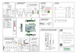
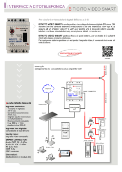
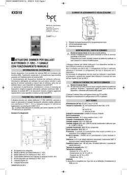
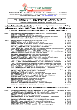
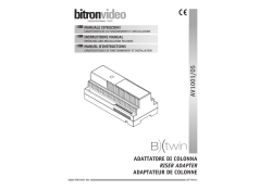
CRISTAL LED
ENERGY TEST - SPY SYSTEM
APPARECCHIO DI EMERGENZA
EMERGENCY LUMINAIRE
MADE IN ITALY
I
UK
ISTRUZIONI PER L'INSTALLAZIONE E L'USO
INSTALLATION AND USE INSTRUCTIONS
CARATTERISTICHE GENERALI:
- Led spia verde per presenza rete.
- Led spia rosso per segnalazione anomalie.
- Funzionamento con batterie ricaricabili al Ni-Cd e al NiMH.
- Dispositivo di ricarica delle batterie a corrente costante.
- Dispositivo di protezione contro la scarica eccessiva della batteria.
- Possibilità di messa in stato di riposo tramite il comando remoto
Commander (opzionale).
Attenzione: In caso di installazione a parete il prodotto deve essere disposto
con il led verde e rosso verso il basso.
BATTERIE:
Sostituire la batteria ogni quattro anni o quando l'autonomia non è più quella
nominale. Il tipo di batteria e la data di produzione sono indicati con una
marcatura sulla batteria (Fig.1). Inoltre c'è uno spazio da riempire a cura
dell'installatore con la data di entrata in funzione.
Attenzione: Le batterie al Ni-Cd e Ni-MH sono inizialmente scariche, la
prima ricarica deve durare almeno 48h.
FUNZIONI DI TEST:
- La lampada esegue due tipi di test temporizzati: il test funzionale e il test di autonomia. I
test funzionale e di autonomia possono essere effettuati anche manualmente con il
Commander quando la batteria è in ricarica di mantenimento.
- Tutti i test manuali vengono eseguiti se ci sono le condizioni ambientali idonee di luce
esterna. Se le condizioni esterne non sono idonee il test viene rinviato al primo verificarsi
delle condizioni idonee. Durante il tempo di attesa il led verde lampeggia per segnalare
che la lampada sta aspettando di potere compiere i test.
Test funzionale: viene effettuato ogni 14 giorni e consiste nella accensione della
lampada di emergenza per una durata di 20 secondi. Per attivare il test funzionale
manuale premere una volta il Commander ON (effettuare una pressione breve della
durata non superiore a 2 secondi)
Test di autonomia: viene effettuato ogni 84 giorni e consiste nella completa scarica della
batteria. Per far partire il test di autonomia premere una volta il Commander ON
(effettuare una pressione lunga della durata non inferiore a 5 secondi).
Disabilitazione dei test: tutti i test temporizzati possono essere inibiti tramite la
pressione di un tasto del Commander OFF, ad una seconda pressione del tasto ON i test
temporizzati verranno riabilitati.
EN 60598-1 EN 60598-2-22
2002/95/CE RoHS Compliant
IP65
230 Vac - 50 Hz
GENERAL CHARACTERISTICS:
- Indicator green Led for the presence of the power supply.
- Indicatore red Led for the warnings signallings.
- Operation with rechargeable Ni-Cd and NiMH batteries.
- Constant current electronic device for the charge of the battery.
- Electrical protection device for the excessive discharge of battery.
- Possibility to be put in the stand-by mode by remote control
Commander (optional)
- Possibility to put a green signal label .
- Plastic body in accordance with the rules in force.
Warning: In case of wall mounting the product must be positioned
with the leds up.
BATTERIES:
It is recommended to substitute each battery every four years or
when the nominal autonomy is not guaranteed. The model and the
date of production of the battery are written on it. Fill the field with the
date of the first starting (Fig.1).
Warning: The Ni-Cd and Ni-MH batteries are sold uncharged:
the first charge must be 48h long.
INSTALLATION: (FIG.2)
-Remove the transparent cover 1 pushing with a screwdriver
in the points 2.
-Unhook the body of the lamp 3 from the base 4 with a screwdriver in the point
5.
-Drill in necessary one of the three possible entries for the power supply cable
and fix the base 4 to the wall using the holes on the base.
-Make the connections as shown on fig.3,4,5,6.
-Hook the body 3 to the base 4 making release the tooth on point 5.
CARATTERISTICHE TECNICHE/TECHNICAL CHARACTERISTICS
ALIMENTAZIONE/ POWER SUPPLY
MASSIMA POTENZA ASSORBITA/ MAX POWER ABSORPTION
GRADO DI PROTEZIONE/ PROTECTION DEGREE
CLASSE DI ISOLAMENTO/ INSULATING CLASS
SEZIONE DEL CAVO/ WIRE DIAMETER
Fig.1
Linergy
6V Ni-Cd
XXX
C2500*5
Batteria Ricaricabile / Rechargeable Battery mm.aaaa
Entrata in funzione / Coming in operation.........................
230Vac - 50Hz
6VA
IP 40-IP65
II
2
0,5 ÷ 5mm
INSTALLAZIONE: (FIG.2)
-Rimuovere il diffusore trasparente 1 facendo leva con
dei cacciaviti nei punti 2.
-Sganciare il riflettore 3 dalla base 4 facendo leva con un cacciavite nel punto 5.
-Forare se necessario uno dei tre possibili ingressi laterali per il cavo di
alimentazione ed applicare
la base 4 al muro tramite gli appositi fori per il fissaggio.
-Eseguire i cablaggi come esposto in fig.3,4,5,6
-Riagganciare il riflettore 3 alla base 4 facendo scattare il denti nel punto 5.
-Riagganciare il diffusore trasparente 1 alla base 4 facendo scattare i denti nei
punti 2.
N.B.
inserire i tappi in dotazione negli appositi spazi laddove
viene inserito il tassello per l’installazione, al fine di per
garantire la tenuta stagna dell’apparecchio.
N.B.
In order to ensure the watertight integrity
of the fitting insert the covers coming with the product
in the reserved places where the screws anchors are
inserted.
5
4
5
2
2
INSERIRE IL RACCORDO
IN DOTAZIONE PER GARANTIRE
LA TENUTA STAGNA.
1
3
INSERT THE IP65 CONNECTOR
SUPPLIED TO ENSURE THE WATERTIGHT INTEGRITY OF THE FITTING.
Fig.2b
2
Fig.2
2
ENERGY TEST - AUTODIAGNOSI LOCALE / SELF TEST
INSTALLAZIONE STANDARD - INIBIZIONE
STANDARD INSTALLATION - INHIBITION
COLLEGAMENTI ELETTRICI / WIRING DIAGRAMS
- NON PERMANENTE / NON MAINTAINED
L
N
NON PERMANENTE
NOT MAINTAINED
230Vac - 50Hz
INTERRUTTORE
ESTERNO
EXTERNAL
TEST BUTTON
Fig. 3
1 2 3 4 5 6
SE
A B SA
CONFIGURAZIONE DEL PRODOTTO PER L’UTILIZZO DEL COMMANDER:
HOW TO CONFIGURE THE PRODUCT FOR THE USE WITH COMMANDER:
Presenza
RETE
Abilitazione
Emergenza
COMMANDER
A
ON
OFF
B
Collegare il Commander ai morsetti A e B della lampada (rispettare la polarità).
Tenere premuto Commander OFF per 11 secondi circa.
Tutti i prodotti sono ora in modalità INIBIZIONE.
Tenere premuto Commander ON per 11 secondi circa. Tutti i prodotti sono ora in modalità REST
MODE.
Se è necessario ritornare in modalità INIBIZIONE tenendo premuto Commander OFF per 11
secondi circa
Connect the Commander to the A and B terminals of the fitting. (respect the polarity).
Keep pushed Commander OFF for about 11 seconds. Now all the products are in the
INHIBITION mode.
Keep pushed Commander ON for about 11 seconds. Now all the products are in the REST
MODE.
If it is necessary to go back to the INHIBITION mode, keep pushed Commander OFF for about
11 seconds.
N.B. Dovendo collegare insieme i morsetti A e B di diversi prodotti evitare di collegare il morsetto
A di qualche prodotto col morsetto B di altri prodotti.
N.B. When connecting together the A and B terminals of many products avoid connecting The A
terminal of some products with the B terminal of some other products.
COLLEGAMENTI ELETTRICI / WIRING DIAGRAMS
- NON PERMANENTE / NON MAINTAINED
COMMANDER
230Vac
L
N
REST MODE
(OPTIONAL)
Presenza
RETE
Abilitazione
Emergenza
ON
COMMANDER
A
OFF
NON PERMANENTE
NOT MAINTAINED
230Vac - 50Hz
A
B
I
L
I
T
A
Z
I
O
N
E
INTERRUTTORE
ESTERNO
B
EXTERNAL
TEST BUTTON
1 2 3 4 5 6
SE
A B SA
Fig. 8
A
B
I
L
I
T
A
Z
I
O
N
E
CENTRALIZZATE SPY SYSTEM / CENTRALIZED SPY SYSTEM
COLLEGAMENTI ELETTRICI / WIRING DIAGRAMS
- NON PERMANENTE / NOT MAINTAINED
L
N
NOT MAINTAINED
230Vac - 50Hz
INTERRUTTORE
ESTERNO
B
A
A
EXTERNAL
TEST BUTTON
B
1 2 3 4 5 6
SE
A B SA
Fig. 10
Massimo 128 Plafoniere su questa linea Bus. Lunghezza massima del Cavo 500m / Max 128 luminaires on this Bus Line. 500m Max Cable Extension..
Terminare il Bus
su quest’ultima
Plafoniera.
T
Plafoniere al Quarto Piano / Fourth Floor
Massimo 128 Plafoniere su questa linea Bus. Lunghezza massima del Cavo 500m / Max 128 luminaires on this Bus Line. 500m Max Cable Extension..
Terminare il Bus
su quest’ultima
Plafoniera.
Bus Termination
T
T
Plafoniere al Terzo Piano / Third Floor
Plafoniere Locali Tecnici 2 / Luminaires Technical locals 2
Massimo 128 Plafoniere su questa linea Bus. Lunghezza massima del Cavo 500m / Max 128 luminaires on this Bus Line. 500m Max Cable Extension.
Terminare il Bus
su quest’ultima
Plafoniera.
Plafoniere Locali Tecnici / Luminaires Technical locals
Massimo 128 Plafoniere su questa linea Bus.
Lunghezza massima del Cavo 500mt.
BUS 1
Bus Termination
BUS 2
T
IN
T
T
Massimo 128 Plafoniere su questa linea Bus. Lunghezza massima del Cavo 500m
Terminare il Bus
sul Repeater. SS-REP/2
Bus Termination
BUS MASTER
on the Repeater.
T
Plafoniere al Secondo Piano / Second Floor
Terminare il Bus
su quest’ultima
Plafoniera.
OUT
T
Plafoniere al Primo Piano / First Floor
BUS 1
BUS 2
BUS 3
BUS 4
Massimo 128 Plafoniere su questa linea Bus. Lunghezza massima del Cavo 500m
Plafoniere Palazzina Uffici / Luminaires Offices buildings
Terminare il Bus
su quest’ultima
Plafoniera.
T
SS-REP/4
BUS MASTER
N
OUT
Plafoniere al Piano Terra / Downstairs
Massimo 128 Plafoniere su questa linea Bus. Lunghezza massima del Cavo 500m
Linea Bus 1
Linea Bus 2
Plafoniere Palazzina Officine / Luminaires workshops buildings
Rete di Alimentazione \ Power 230Vac
IN
Plafoniere al Piano Seminterrato / Basement
Fig.12
L
Collegamento alla centrale Spy System con Ripetitori Bus a 4 e 2 Vie / Connection to the SPy System using to 2 or 4 - ways repeaters.
Terminazione del Bus / Bus Termination
A B
RESISTENZA/RESISTOR
120 OHM
Rispettare la polarità del Bus.
Respect the polarity of the Bus.
A B
Il Bus:
Il Bus che deve essere utilizzato per lo Spy System
deve avere un cavo bi-polare (minimo 2x0,50mm2)
twistato e schermato. La tipologia di connessione deve
essere Punto Punto, ossia si deve entrare ed uscire da
ogni plafoniera come è visibile negli schemi a lato. Il
collegamento deve essere fatto rispettando le polarità di
“A” e “B” sia sulle lampade che sulla centrale.
BA
Avvertenze:
Per un corretto funzionamento di tutto l’impianto occorre
Terminare il Bus collegando la resistenza fornita con la centrale
o con il ripetitore, in parallelo ai morsetti A-B, di tutte le lampade
che si trovano alla fine delle linee di ogni serie.
Nel caso in cui l’ultimo apparecchio sia un ripetitore occorre
terminarlo come se fosse una plafoniera, lo strip si trova tra le
morsettiere di Bus IN e Bus OUT.
The Bus:
Fig.13
Attention:
For a correct operation of the whole plant it is necessary to
terminate the bus, inserting the resistir, supplied with the plant or
with the repeater, in parallel to the terminals A-B of the terminal
block, at the end of the lines of each series.
If at the end there is repeater, it is necessary to terminate it as if it
were a fixture, the strip is between the terminal board of Bus In
and Bus Out.
SEGNALAZIONI LED / LED SIGNALLING
The bus used for the Spy System must have a bipolar,
twisted and shielded cable (min. 2x0,5 mm²). The
connection is a Point to Point type, i.e. input and
output of the fixtures must be, as shown in fig. no. 2.
The connection must be done respecting the polarity
of "A" and "B" both on the lamps and on the plant.
SIGNIFICATO / LED MEANING
VERDE ACCESO FISSO / GREEN ON, NOT FLASHING
PRESENZA RETE, NESSUNA ANOMALIA / MAINS SUPPLY ON, NO WARNING
VERDE LAMPEGGIANTE / GREEN FLASHING
TEST IN CORSO / TEST IN PROGRESS
ROSSO LAMPEGGIANTE LENTO / RED SLOW FLASHING
TEST DISABILITATI - LAMPADA INIBITA* / TEST DISABLED - LUMINAIRE INHIBITED*
ROSSO LAMPEGGIANTE VELOCE / RED SLOW FLASHING GUASTO BATTERIA / BATTERY FAULT
ROSSO ACCESO FISSO / RED ON, NOT FLASHING
LAMPADA GUASTA / LUMINAIRE FAULT
COD. IP65
N.LED
CL24N10EGRT800
CL24N10EGRC800
POWER AUT.
FLUX (lm)
FLUX (lm)
BATTERY
–
–
NiCd 6V 1,8Ah
NiCd 6V 1,8Ah
BATTERY
VA
40
40
6
6
1h
1h
800
800
12h
12h
Fig. 3
Fig. 3
Le caratteristiche degli articoli e dei dati tecnici
possono subire variazioni senza preavviso
ed obbligo di comunicazione per le ns.esigenze
di fabbricazione e per il miglioramento degli apparecchi.
The characteristics of the articles and the
technical data contained in this paper can be
modified without notice according to our
exigency.
CONDIZIONI DI GARANZIA / WARRANTY CONDITION
La garanzia sugli apparecchi di emergenza è di 2 anni dalla data di vendita. La garanzia decade se
il prodotto è stato manomesso o riparato da personale non autorizzato LINERGY.
The warranty on the emergency luminaire is 2 years from the sales date. The warranty voids if the
product has been mishandled or repaired by personnel not authorized by LINERGY.
Il cassonetto barrato sull’apparecchio specifica che il prodotto deve essere
consegnato ai centri di raccolta autorizzati per un corretto smaltimento.
Rivolgersi all’ufficio competente del proprio ente locale per informazioni sulla
raccolta e sui termini di legge.
The crossed out waste bin symbol indicates that the product should be taken to
an authorized waste collection centre which can dispose of it properly. For
information on waste collection centres and on current waste disposal
legislation, please contact your local waste disposal authority.
LINERGY S.R.L. - via A. De Gasperi 9 - Acquaviva Picena (AP) - ITALY - tel.0735.5974 - fax 0735.597474 - www.linergy.it - [email protected] - ISTCLET - Ver. 1.0
© Copyright 2026 Paperzz