MANUALE 01 OFFICINA
WORKSHOP MANUAL
COD. 30 92 01 80
Varianti al Manuale per modelli V1000 G5 e 1000 SP - Cod. 1792 01 60
Additions to the Workshop manual for the models V1 000 G5 and 1000 SP - Cod. 1792 01 61
Le IIJustrazioni e descrizioni di questa manuale si intendono fornite a titolo indicativo. La Casa si riserva
pertanto iI diritto di apportare ai mOlocicll, in qualsiasi momenta e senza avviso. quelle modiflche che
ritenesse utifi per II migliorarilenta a per qualsiasi esigenza dl carattere costruHivo e commerciale.
The illustrations and description in this booklet are indicative only and the manufacturer reserves itself
the right to Introduce any modification it may deem necessary for better performance or for constructive
or commercial reasons without prior notice.
GBM S.pA MOTO GUZZI
SERVIZIO PUBBLICAZIONI TECNICHE I TECHNICAL PUBBLICA nONS
Cod. 30 92 01 80
Stampato in Italia I Printed in Italy- D.E.Ca. - Ravenna 500 K - 10/'93
INDEX
INDICE
MAIN FEATURES
CARATTERISTICHE GENERALI
pageS
pag.5
APPARECCHI 01 CONTROLLO E COMAIND~
INSTRUMENTS AND CONTROLS
pag.8
page 8
pag . 10
page 10
ENGINE OVERHAUUNG AND CHI=CKiNG
REVISIONE E VERIFICA DEL MOTORE
page 11
pag . 11
12.6
12.6
Valvo Ie e guidavalvole
Valves and valve-guides
12.12 Cilindri
12.12 Cylinders
12.13 Pistoni
12.13 Pistons
12.16 Montaggio delle bielle suli'albero motore
12. 16 Fitting of the connecting rods on the crankshaft
12.18 Controllo peso per I'equilibratura dell'albero
motore
12.18 Weight check for crankshaft balancing
ENGINE LUBRICATION
page 15
14.1
Pompa olio di mandata
14.1
Oil delivery pump
FUEL FEEDING
ALIMENTAZIONE
page 16
pag.16
15.1
Carburatori
15.1
SOSPENSIONE POSTERIORE
Carburetors
REAR SUSPENSION
pag. 18
page 18
FRONT SUSPENSION
SOSPENSIONE ANTERIORE
pag.20
page 20
SWINGING ARM
FORCELLONE OSCILLANTE
pag . 23
page 23
3
RUOTE
WHEE~S
pag.24
page 24
23.1
Ruota anteriore
23.1
Front wheel
23.3
Ruota posteriore
23.3
Rear wheel
23.5
Pneumatici
23.5
Tyres
23.10 Impianti idraulici per freni
23.10 Brake hydraulic system
IMPIANTO ELETTRICO
ELECTRICAL EQUIPMENT
24.2
pag. 28
Alternatore· Regolatore "DUCATI"
24.2
page 28
Alternator· Regulator "DUCA T!.'
24.5
Motorino awiamento "VAL EO"
24.5
Starter motor "VALEO"
24.6
Accensione elettronica "MOTOPLAT"
24.6
Electronic ignition "MOTOPLA T"
24.7
Accensione elettronica "MAGNETI MARELLI
DIGIPLEX"
24.7
Electronic ignition "MAGNET! MARELLI
DIGIPLEX"
SCHEMA IMPIANTO ELETTRICO
WIRING DIAGRAM
page 35
pag . 35
4
25.1
Legenda schema impianto elettrico
(accensione elettronica MOTOPLAT)
25.1
Electric system scheme legend
(MOTOPLA T electronic ignition)
25.2
Legenda schema impianto elettrico
(accensione elettronica MAGNETI
MARELLI . DIGIPLEX)
25.2
Electric system scheme legend
(MAGNET! MARELLI . DIGIPLEX electronic
ignition)
•
CARATTERISTICHE GENERAL!
MAIN FEATURES
MOTORE
Bicilindrico a 4 tempi
Disposizione cilindri ...... ..... .................. a "V» di 900
Alesaggio ........... ...... ... ......... ..... ...... ... ........... mm 88
Corsa ....................... .. ................................... mm 78
Cilindrata totale .......................................... cc 948,8
Rapporto di compressione .............................. 9,5:1
Potenza massima .. 52 KW (71 CV) a 6800 girilmin.
Coppia massima .77 Nm (7,9 kgm) a 5800 girilmin .
Potenza fiscale ........ ....... .............. ................. CV 12
ENGINE
4·stroke, twin cylinder
Cylinder configuration .. .......................... 91J' V-twin
Bore: ............................................................. 88 mm
Stroke: ...................................,...................... 78 mm
Capacity: ............................................ .... 948.8 cc
Compression ratio: ..................................... ..... 9.5:1
Max. power: ................ 52 KW (71 CV) at 6800 rpm
Max. torque: ............. 77 Nm (7,9 kgm) at 5800 rpm
DlSTRIBUZIONE
A valvole in testa con aste e bilancieri.
VALVE GEAR
O.H. V. push rod operated rocker arms
ALiMENTAZIONE
N. 2 carburatori "Dell'Orto" tipo PHF 36 DD (destro)
PHF 36 DS (sinistro) .
FUEL SYSTEM
2 Del/'Orto carburettors PHF 36 DO (right) and PHF
36 OS (left) .
ACCENSIONE
Elettronica a captatore magnetico , con anticipo va·
riabile "MOTOPLAT".
Dati di accensione :
• anticipo iniziale (fisso).
.. ....... 20+3°
• anticipo massimo (fisso+automatico) ..... 34°+35°
Traferro tra captatore e rotore: ............. mm 0,2+0,4
Candele di accensione: NGK BP 6 ES; Bosch W 7
DC; Champion N 9 YC.
Distanza tra gli elettrodi delle candele: ....... mm 0,6.
Bobine di accensione: n. 2 montate sui telaio.
In alternativa montata I'accensione elettronica digi·
tale a scarica induttiva "MAGNETI MARELLI .
DIGIPLEX".
Candele di accensione: NGK BP7ES, Bosch W5DC
Distanza tra gli elettrodi delle candele; ....... mm 0,7.
IGNITION
Electronic ignition operating by magnetic pick-up;
electronic ignition advance "MOTOPLA TOO.
Ignition timing:
• Ignition advance (fixed) .. .. .......................... 2'+3'
• Ful/ advance (static and automatic) ....... 34°+35"
Rotor-pick up gap: .............. .. ................ mm 0, ~0,4
Spark plugs: NGK BP 6 ES; Bosch W 7 DC; Champion N9 YC.
Spark plug gap: .......................................... 0,6 mm.
2 ignition coils mounted on frame.
The "MAGNET! MARELLI - DIGIPLEX" digital electronic ignition with inductive discharge may be
mounted as an alternative.
Spark plugs : NGK BP7ES, Bosch W5 DC
Spark plug gap: .................. .................... .. .. O. 7 mm.
GENERATORE AL TERNATORE
Montato sulla parte anteriore dell'albero motore (14V·
25A).
GENERATOR/ALTERNATOR
On front of crankshaft (14V-25A).
AVVIAMENTO
Elettrico mediante motorinG awiamento munito di
innesto a comando elettromagnetico. Corona dentata
fissata al volano motore.
Comando a pulsante (START) posto sui lato destro
del manubrio.
Batteria (12V·24 Ah)
STARTER
Electric starter motor with electromagnetic ratchet
control.
Ring gear on the flywheel. START push-button on
right handlebar.
Battery (12V-24 Ah)
LUBRIFICAZIONE
Sistema a pressione con pompa ad ingranaggi.
Filtri a rete ed a cartuccia montati nella coppa del
basamento.
Pressione normale di lubrificazione kg/cmq 3,8+4,2
(regolata da apposita valvola montata nella coppa
del basamento).
Trasmettitore elettrico per segnalazione insufficiente
pressione sui basamento.
LUBRICA TlON
Pressure system with gear pump.
Wire mesh and cartridge filters fitted in the oil sump.
Normal lubrication pressure 3,8+4,2 kg/cmq (controlled by the valve fitted in the oil sump).
Electric transmitter that indicates low pressure on the
crankcase.
e
5
TRASMISSIONI
Frizione
Tipo a secco a due dischi condotti. E' posta sui volano
motore. Comando mediante leva sui manubrio (Iato
sinistral·
Trasmissione primaria
Ad ingranaggi, rapporto 1:1,235 (Z=17/21).
Primary drive
By gears, 1:1.235(Z=17/2 1).
Cambio
A cinque marce con ingranaggi sempre in presa ad
innesto frantale . Parastrappi incorporato.
Comando con leva a pedale posta sullato sinistra del
veicolo.
Rapporti cambio :
I ' marcia = 1:2 (Z= 14/28)
2' marcia = 1:1,388 (Z= 18/25)
3'marcia= 1:1,047 (Z=21 122)
4' marcia = 1 :0,869 (Z=23/20)
5' marcia = 1 :0 ,750 (Z=28/21)
Gearbox
5-speed, front engaging, constant mesh. Incorporated Cush drive.
Control pedal on left side of machine.
Gear ratios:
1st 1:2 (Z=14/28)
2nd 1:1.388 (Z=18/25)
3rd 1:1 .047 (Z=21/22)
4th 1:0.869 (Z=23/20)
5th 1:0.750 (Z=28/21)
Trasmissione secondaria
Ad albero con giunto cardanico ed ingranaggi.
Rapporto: 1 :4,714 (Z=7/33)
Rapporti totali (motore-ruota):
I' marcia = 1 :11 ,647
2' marcia = 1 : 8,088
3' marcia = 1: 6,100
4' marcia = 1: 5,063
5' marcia = 1: 4,367
Final drive
Cardan shaft with gears
Ratio: 1:4,714 (Z=7/33)
Overall gear ratios (engine-wheel)
1st gear 1:11 ,647
2nd gear I: 8,088
3rd gear 1: 6, 100
4th gear I: 5,063
5th gear I : 4,367
TElAIO
FRAME
Modular duplex tubular cradle.
Tubolare a doppia cul la scomponibile.
SOSPENSIONI
Anteriore: forcella telescopica «MOTa GUZZI", con
regolazione separata del precarico molle e della
frenatura degli ammortizzatori.
Posteriore: forcellone oscillante con molle a spirale
regolabili concentriche agli ammortizzatori idraulici di
tipo regolabile.
RUOTE
Fuse in lega leggera con cerchi nelle misure:
- anteriore: 18 MT 2.50 H2
- posteriore: 18 MT 3.00 H2
Oppure a raggi con cerchi nelle misure :
- anteriore: 2.15x I8"
- posteriore: 2.50xI8"
PNEUMATICI
- anteriore: 110/90 V18
- posteriore : 120/90 V18
Tipo: Tubeless 0 Tube-Type
6
TRANSMISSION
Clutch
Dry, twin driven plates. Located on engine flywheel.
Clutch lever on left handlebar.
SUSPENSION
Front: «MOTO-GUZZI patented» telescopic forks;
springs load and dumping effect adjustable.
Rear: swinging arm with adjustable helical springs
around adjustable hydraulic damper.
WHEELS
Light alloy castings.
Rim sizes:
- Front: 18 MT 2.50 H2
- Rear: 18 MT 3.00 H2
Or with spokes:
- Front: 2. 15x18"
- Rear: 2.50xI8"
TYRES
- Front: 110/90 VI8
- Rear: 120/90 VI8
Type: Tubeless a Tube- Type
FRENI
Anteriore: a disco flol\ante con pinza fissa a doppio
cilindro frenante. Comando con leva a mana posta
sullato destro del manubrio. Trasmissione idraulica
indipendente dal freno posteriore;
- 0 disco 300 mm ;
- 0 cilindro frenante 38 mm;
- 0 pompa 13 mm.
Posteriore: a disco flol\ante con pinza fissa a doppio
cilindro frenante . Comando con leva a pedale posta
al centro sullato deslro del veicolo;
- 0 disco 270 mm ;
- 0 cilindro frenante 38 mm ;
- 0 pompa 15,875 mm.
II freno posteriore coliegato mediante trasmissione
idraulica al freno anteriore sinistro, avente nei singoli
componenti Ie stesse dimensioni del freno anteriore
e destro comandato a mano.
BRAKES
Front brakes: floating disc with fixed caliper, twin
brake cylinder. Brake lever on right handlebar. Independent hydraulic circuit for rear brake.
- 0 disc 300 mm;
- 0 brake cylinder 38 mm;
- 0 master cylinder 13 mm.
Rear brakes: floating disc with fixed caliper, twin
brake cylinder. Brake pedal on center-rightofvehicle.
-0 disc 270 mm;
- 0 brake cylinder 38 mm;
- 0 master cylinder 15.875 mm.
The rear brake is connected by a hydraulic circuit to
the left front brake; the left front brake has the same
dimensions as the front brake controlled by the brake
lever.
INGOMBRI E PESO
Passo (a carico)
Lunghezza massima
Larghezza massima
Altezza massima (cruscotto)
Altezza minima da terra
Peso (a secco)
DIMENSIONS AND WEIGHT
Wheelbase
Overall length
Overall width
Height (dashboard)
Minimum height from ground
Weight (dry)
e
m 1,495
m 2,165
m 0,770
m 1,170
m 0,175
kg 215
PRESTAZIONI
Velocita massima con il solo pilota a bordo: 200 km/h.
Consumo carburante: litri 5 per 100 km (norme CUNA).
1.495 m
2.165m
0.770 m
1. 170 m
0. 175m
215 kg
PERFORMANCE
Max. speed with one rider: 200 km/h.
Fuel consumption: 5 Itll00 km (CUNA standard)
Rifornimenti
Parti da rifornire
Litri
Prodotti da impiegare
Serbatoio carburante (riserva It. 4 circa)
22,5 ca.
Benzina super (97 NO-RM/min .)
Coppa motore
3
Olio «Agip nuovo SINT 2000 SAE 10 W/40"
Scatola cambio
0,750
Olio «Agip Rotra MP SAE 80 W/9 0 ..
Scatola Irasmissione
(Iubrificazione coppia conical
0,250
di cui:
0,230
0,020
Olio «Agip Rotra MP SAE 80 W/90»
Olio «Agip Rocol ASO/R .. oppu re
Molykote Tipo «A»
Forcella telescopica (per gamba)
0,070
Liquido «Agip ATF Dexron »
Impianto frenante anteriore e posteriore
-
Fluido «Agip Brake Fluid - Super HD»
Parts to fill up
Quantity
Recommended product
Fuel tank (reserve 4 It. about)
appr. 22,5
Supergrade petrol (97 NO-RM/min.)
Crankcase sump
3
Agip nuovo Sint 2000 SAE 10W/40 oil
Gearbox
0.750
Agip Rotra MP SAE 80W/90 oil
Rear drive box
(bevel gear lubrication)
0.250
of which
0.230
0.020
Agip Rotra MP SAE 80W/90 oil
Agip Rocol ASO/R oil or type A Molykote oil
Front forks (each leg)
0,070
«Agip ATF Dexron» fluid
Braking system (front and rear)
-
Agip Brake Fluid Super HD
Refuelings
7
APPARECCHI 01 CONTROLLO E
COMANOI
Quadro di controllo (Iig. 1)
1 Commutatore a chi ave per inserimento utilizzatori
e bfoccasterzo.
Posizione «OFF.. veico fo lermo. Chiave estraibife
(nessun contatto) ;
Posizione «ON .. veicofo pronto per I'avviamento.
Tutti gli utilizzatori sana inseriti. Chiave non estraibile;
Posizione «LOCK .. sterzo bloccato a sinistra.
Motore spento, nessun contatto, chiave estraibile .
Posizione «P .. sterzo bloccato. Motore spento; con
I'interruttore «A .. di lig. 2 in posizione «p .. si ha la fuce
di parcheggio. Chiave estraibile.
Per azionare il dispositivo bloccasterzo ope rare come
segue:
• Ruotare il manubrio verso sinistra.
• Premere fa chiave verso il basso e ruotarla in
senso antiorario sino alia posizione "LOCK .. 0 . P».
ATIENZIONE: non girare la chiave in posizione
«LOCK .. 0 «p .. durante la marcia.
2 Tachimetro contachilometri.
4 Contagiri.
5 Spia (Iuce verde) «Neutral .. indicatore cambio in
lolle. Si accende con il cambio in lolle.
6 Spia (Iuce verde) per lampeggiatori sinistri.
7 Spia (Iuce bleu) luce abbagliante.
8 Spia (Iuce rossa) pressione olio. Si spegne quando la pressione e sufficiente ad assicurare la
lubrilicazione del motore. Se la spia non si spegne, la pressione non e quella prescritta; in tal
caso, occorre lermare immediatamente iI motore
ed effettuare Ie opportune ricerche .
9 Spia (Iuce rossa) erogazione corrente del generatore. Si deve spegnere appena il motore ha raggiunto un certo numero di giri.
10 Spia (Iuce arancio) ri serva carburante.
11 Com mutatore per inserimento lampeggiatori di
emergenza.
12 Spia (Iuce verde) per lampeggiatori destri.
13 Spia (Iuce verde) per fuci di posizione.
8
INSTRUMENTS AND CONTROLS
Control panel (fig. I)
1 Key switch for devices and steering lock.
Position «OFF.. vehicle stationary. Key removable
(no contact).
Position «ON» vehicle ready to be started.
All circuits are on. Key not removable.
POSition "L OCK» steering locked to the left.
Engine off, no contact, key removable.
Position «p .. steering locked. Engine off; with switch
«A .. ottig. 2 in position «P" the parking light is on. Key
removable.
In order to use tile steering lock mechanism, proceed
as follows:
• Turn the handlebars to the left.
• Press the key down and turn anti-clockwise to
pOSition (f LOCK» or «P».
WARNING: Neverturn the key to position " LOCK»
or "p" when the engine is running_
2 Odometer, tachometer.
4 Rev counter.
S Pilot light (green) «Neutral» for neutral position.
Lights up when tile gearbox is in neutral.
6 Pilot light (green) for L.H. flashing indicators.
7 Pilot light (blue) for main beam.
8 Oil pressure pilot light (red). Goes out when the oil
pressure is sufficient to ensure engine lubrication.
If the pilot light doesn't go out, then the pressure
is not at the required level; in this case, stop tile
engine immediately and check the fault.
9 Pilot ligh t (red) forgeneratorcurrent output. Should
go out when the engine reaches a certain number
of revs.
10 Petrol tank reserve pilot light (orange).
11 Switch for hazard warning lights.
12 Pilot light (green) for R.H. flashing indicators.
13 Pilot light (green) for parking light.
Interruttori comando luci (fig. 2)
Son a montati sui lata sin istro del manubria.
Interruttore "A»
• Posizione .. 0» luci spente.
• Posizione .. p" luci di parcheggio.
• Posizione .. H» accensione lampada biluce.
Interruttore «8» (lights)
Con I'interruttore «A» in posizione «H».
• Posizione .. LO» luce anabbagliante.
• Posizione .. HI» luce abbagliante.
Light switches (fig. 2)
These switches are on the left handlebar.
Switch "A»
• Position .. 0 " lights off.
• Position .. p .. parking lights on.
• Position .. H» twin-filament headlamp on.
Switch «8» (lights)
With switch ..A » in position .. H».
• Position «LO» dipped beam.
• Position «HI" main beam.
Pulsante per avvisatore acustico, passing e interruttore comando lampeggiatori (fig. 2)
Sana montati sui lata sinistro del manubria:
Pu lsante "C» (Horn) comando avvisatore acustico.
Pulsante ,,0» (passing) comando luce a sprazzo.
Pulsante «E» (Turn) .
• Posizione .. R» comando lampeggiatori destri.
• Posizione .. L» comando lampeggiatori sinistri.
• Premere I'interruttore per disinserire i lampeggiatori.
Horn button, passing and headlamp flasher (fig. 2)
These are mounted on the left handlebar:
Push-button "C .. (Horn) sounds the electric horn
when pressed.
Push-button "D» (Passing) flashing light control.
Push-button "E" (Turn):
• position .. R" for right turn signals control.
• position .. L .. for left turn signals control.
• press the switch to disconnect flashers .
Leva comando "Choke» (" F» di fig. 2)
La leva comando dispositivo di avviamento a motore
freddo (CHOKE) Ii situata sui lata sinistro del manubria:
• .. 1» posizione di avviamento .
• «2» posizione di marcia.
«CHOKE» control (<<F .. in fig. 2)
The .. CHOKE» is on the left handlebar and is used for
cold starts.
• Position .. I .. CHOKE on; starting position.
• Position ..2" CHOKE off; engine running.
Pulsante avviamento ed interruttore di fermo
motore (fig . 3)
Sana montati sui lata destro del manubria.
Can chiave .. 1» di fig. 1 (posizione .. ON »), il veicolo
Ii pronto per I'avviamento.
Per avviare iI motore operare come segue:
• accertarsi che I'interruttore .. 8» sia in posizione (run);
• tirare a fonda la leva della frizione;
• se il motore Ii freddo portare la levetta .. F»
.. CHOKE" in posizione di avviamento .. 1» vedi fig. 2.
• premere il pu lsante di avviamento .. C» (start) .
Per fermare il motore in caso di emergenza, occorre :
• spostare I'interruttore ,,8» in posizione (off) .
Fermata il motore, ruotare la chiave del commutatore
di fig. 1 in posizione .. OFF» ed estrarre la chiave dal
commutatore .
Starter button and engine stop switch (fig. 3)
These are mounted on the right handlebar.
With the key «1 » in fig. 1 (position .. ON»), the vehicle
is ready for starting. To start the engine:
• check that switch .. 8 .. is in position (run);
• pull the clutch lever in to disengage the clutch fully;
• if the engine is cold, put the «CHOKE» control ..F»
in the starting position .. 1.. (see fig. 2);
• press the starter button .. C .. (start) .
To stop the engine in case of emergency:
• turn the switch «8» to position (off).
Once the engine has stopped, turn the key switch (fig.
1) until ..OFF»; remove the key from the switch.
9
•
TABELLA RIASSUNTIVA DELLA MANUTENZIONE E LUBRIFICAZIONE
PERCOARENZE
1500 Km
5000Km
' OOOOKm
Olio molore
R
R
R
Rltro olio a cartuccia
R
Fitlro olio a rete
C
OPEAAlIQNI
20000Km
25000Km
JOOOOKm
35000 Km
<OOOOKm
' 5000Km
SOOOOKm
R
R
R
R
R
R
R
R
R
R
C
C
Fillro aria
lSOOOKm
R
C
R
C
R
C
R
C
C
R
C
R
Fasalura accensione
A
Candela
A
A
R
A
R
A
R
A
R
A
R
Giuoco valvola
A
A
A
A
A
A
A
A
A
A
A
Carburazione
A
A
A
A
A
A
A
A
A
A
A
Serraggio bulloneria
A
A
A
A
Serbaloio carburante, I1l1rl rubineUi,
tubazioni
A
A
A
A
A
A
A
A
OJiocamblo
R
A
R
A
R
A
R
A
R
A
R
Otio trasmissione posteriore
R
A
R
A
R
A
R
A
R
A
R
Cuscinet11ruole e sierzo
A
Otio fOfcelia anteriore
R
R
Molorino avviamento e generatore
A
A
A
R
Au ido impianto rrenante
A
A
A
R
A
A
R
A
A
R
A
Pastiglie !teni
A
A
A
A
A
A
A
A
A
A
A
A = Manutenzione - Contrallo - Regolazione - Eventuale sostituzione. I C = Pulizia. I R = Sostituzione.
Saltuariamente controllare illivello dell'elettrolito nella batteria e lubrificare Ie articolazioni dei comandi
ed i cavi flessibili; ogni 500 km controllare illivello dell'ol io motore.
In ogni caso sostituire I'olio motore almeno una volta all'anno.
Con ruote a raggi montate, controllare periodicamente la t ensione dei raggi ruota .
•
MAINTENANCE AND LUBRICA TlON OPERA TlONS
MILEAGE COVERED
ITEMS
l 000m1.
(1500 Km)
Engine 011
R
Oil filler cartridge
R
Wire gauze oil filler
C
Air r;iler
Ignition timIng
15000 ml.
18000 mi.
3000 mi.
6000 mi.
9000 mi.
12000 mi.
2 1000 mt
24tlOO ml. 27000 mi. 30000ml.
(SOOOKm) (I OOOOKm) (1 5000Km) (20000 Krn) (25000 Km) (30000 Km ) (35000Km) (40000 Km) (45000 Km) (50000 Km)
R
R
R
R
R
R
R
A
C
R
R
C
R
C
A
R
R
R
R
R
C
C
R
C
C
R
C
R
A
A
Sparkp/ugs
A
A
R
A
R
A
R
A
R
A
R
Rocker clearance
A
A
A
A
A
A
A
A
A
A
A
Carburarion
A
A
A
A
A
A
A
A
A
A
A
Nuts and boIlS
A
A
Fuel lani<. tap filters and pipes
A
A
A
A
A
A
A
Gearbox oil
R
A
R
A
R
A
R
A
R
A
R
Rear drive box oil
R
A
R
A
R
A
R
A
R
A
R
Wheel and steering bearings
Front larks oil
Starter motor and generlilof
A
A
R
R
· A
A
R
Brake system fluid
A
A
A
R
A
A
R
A
A
R
A
Brake pads
A
A
A
A
A
A
A
A
A
A
A
A = Maintenance - Inspection - Adjustment - Possible replacement.! C = Cleaning.! R = Replacement.
Occasionally check the electrolyte level in the battery and lubricate control joints and cables; every 500
km (300 miles) check the engine oillevel.
The oil should be changed at least once a year, in any case.
With assembled spoked wheels, periodically check the tension of the spokes.
10
REVISIONE E VERI FICA DEL MOTORE
II
ENGINE OVERHAULING AND
CHECKING
11
12.6
VALVOLE E GUIDAVALVOLE
12.6
VALVES AND VALVE-GUIDES
-
-
=
=
.......:0 8.000+8.022 mm
07.987+7.972 mm
'" 7.980·.7.965 mm
VALVOLA
ASPIRAZIONE
VALVOLA
SCARICO
;-
EXHAUST
VAL VE
INLET VALVE
"-
./
o 43.B+44mm
45°30'±5'
Z
'" 36.9+37.1 mm
./
12.12 CILINDRI
12.12 CYLINDERS
Selezionatura cilindri (mm)
Cylinders range (mm)
GRADO A I A SIZE
GRADO B I B SIZE
GRADO C I C SIZE
88,000+88,006
88,006+88,012
88,012+88,018
12.13 PISTONI
12.13 PISTONS
Selezionatura pistoni (mm)
Pistons range (mm)
GRADO A I A SIZE
GRADO B I B SIZE
GRADO C I C SIZE
87,968+87,974
87,974+87,980
87,980+87,986
088
0.30+0.45
1.490. 1.4 78
4.02+4 .04
3.990+3.978
1.490+1.478
0.25+0.50
021.994+21 .998
59.984+59.970
o 22.000+22.006
Valori in mm
12
Values in mm.
12.16 MONTAGGIO DELLE BIELLE SULL'ALBEROMOTORE
12.16 FITTING OF THE CONNECTING RODS
ON THE CRANKSHAFT
II gioco di montaggio tra cuscinetto e perno di biella
The assembly clearance between the bearing and
the connecting rod pin ranges from a minimum of
0.022 mm to a maximum of 0.064 mm.
The clearance between the connecting rod shim
adjustment and those of the crankshaft is 0.30+0.50
mm. Fit the connecting rods on the crankshaft, tighten
the nuts on the caps with a dynamometric wrench
using a tightening torque of 4.6+4.8 kgm.
e di mm minima 0,022, massimo 0,064.
II gioco tra i rasamen ti delle bielle e quelli dell'albero
motore di mm 0,30+0,50.
Montare Ie bielle sull'albero motore, bloccare i dadi
sui cappelli can chiave dinamometrica can cop pia di
serraggio di Kgm 4,6+4,8.
e
N.B. - Guardando il motore dal lata frizione i piani
fresati (delle bielle e cappelli) devono essere sullo
stesso lalo e i fori di lubrificazione pralicati sulle bielle
dovranno essere rivolti verso destra.
N.B. - Looking at the engine from the clutch side, the
milled surfaces (of the connecting rods and caps)
must be on the same side and the lubrication holes
made in the connecting rods must be turned towards
the right.
~------
22.007-'--22. 20 - - ; - - --
----,
04
139.975 +- 140.025
Massimo scarto di parallelismo complanarila
Ira i due assj misurati alia distanza di m/m:
Max pBfaltelism andcompJanar;/udifference
/:Ie/ween both axis measured at:
200 ± O.10
200
Coppia serragglo dadi' Torque loading
4.6 7 4.8
DIAMETRO BOTTONE DI MANOVELLA'
o STANDARD
M INORATO mm 0,254
MINORATO mm 0,508
MINORATO mm 0,762
44,008+44,020
43,754+43,766
43,500+43,512
43,246+43,258
CRANKSHAFT PIN DIAMETER:
STANDARD DIA.
UNDER SIZED 0.254
44,008+44,020
mm
43,754+43,766
Dali di accoppiamenlo Ira spinotto e boccola
o INTERNO DELLA
BOCCOLA PIANTATA
E LAVORATA mm
0SPINOTTO
22,007
22,020
21,994
21,998
mm
GIUOCOFRA
SPINOTTO E BOCCOLA
mm
0,009+0 ,26
Spessori dei cuscinetti di bielia
CUSC INETTO NORMALE
(PRODUZIONE) mm
da 1,535
a 1,544
UNDER SIZED 0.508
mm
UNDER SIZED 0.762
43,500+43,512
mm
43,246+43,258
Gudgeon pin and bushing coupling data
INTERNAL DlA. DF
CLEARANCE BETWEEN
GUDGEON PIN DIA.
BUSHING PRESSED
GUDGEON PIN
mm
AND MACHINED mm
AND BUSHING mm
22,007
22,020
21 ,994
21,998
0,009-;.0,26
Thicknesses of the connecting rod bearings.
cuscinetti per 0 perno di bieJla
minorato di mm
0,254
0,508
0,762
1,662
1,671
1,789
1,798
1,916
1,925
NORMAL BEARING
(PRODUCTION) mm
from 1,535
to 1,544
bearings (or connecting rod pin
dia. undersized b mm
0,254
0,508
0,762
1,662
1,671
1,789
1,798
1,916
1,925
13
12.18 CONTROllO PESO PER l'EQUILIBRATURA DEll' AlBERO MOTORE
12.18 WEIGHT CHECK FOR CRANKSHAFT
BALANCING
le bielle complete di dadi e bulloni devono risultare
equilibrate nel peso.
Eammessa tra loro una differenza di grammi 3.
Per equilibrare staticamente I'albero motore occorre
applicare sui bottone di manovella un peso di:
Kg. 1,704 per albero motore marcato «4 .. e bielle
aventi peso di 591 +600 gr.
Kg. 1,723 per albero motore marcato «5 .. e bielle
aventi peso di 601+610 gr.
Kg . 1,742 per albero motore marcato «6 .. e bielle
aventi peso di 611+620 gr.
Kg. 1,760 per albero motore marcato «7 .. e bielle
aventi peso di 621 +630 gr.
The connecting rods complete with nuts and bolts
must have a balanced weight.
There is a tolerance of 3 grams.
For a static balancing of the crankshaft, the pin must
bear a weight of:
- 1.704 kg for crankshaft marked ,,4 .. and connecting rods with a weight of 591+600 g.
- 1.723 kg for crankshaft marked «5» and connect·
ing rods with a weight of 601+610 g.
- 1.742 kg for crankshaft marked «6» and connect·
ing rods with a weight of 611+620 g.
1.760 kg for crankshaft marked« 7. and connecting rods with a weight of 621+630 g.
0 1nlemo del Ol~tti di banco per rleambio SIgIa 1den~1ical':1one minorazlOf'li
Inlomw dill. 01 main bearing for spare parts
..
ki;mlirlCa/IOfl
F. ~
37.800+37.816
M2
53.800+53.8 19
M2
~
"
.0
37.600·>37.616
M4
53.600+53.619
M4
,
37.400+37.416
M6
53.400+53.419
M6
E O
i ",
0
GIOCO 01 AC COPPIAMENTO CON l 'AlBEAO MOTOAE ..
mtm 0,028+0,060
CRANKSHAFT COUPLING CLEARANC&O.OZS.O.060 mm
14
S;gJa identlrlcazione rninorazioni
identification code
GIOCO 01 ACCOPPIAMENTO CON L'ALBERO MOTORE",
mlm 0,040+0,075
code
14.1
LUBRIFICAZIONE DEL MOTORE
III
ENGINE LUBRICA nON
POMPA OLIO 01 MANDATA
14.1
OIL DELIVERY PUMP
Verifiche e controlll
Se si riscontrano difetti dovuti alia pompa contrellare:
I'altezza degli ingranaggi che deve risultare contenuta entre mm 15,973+16,000 ; e quello delle sedi sui
corpo pompa che deve risultare entro mm
16,032+16,075.
Qualora detti particolari non risultassero contenuti in
tali valori, occorre senz'altre sostituirli.
Inspections and controls
In case of improper operation of the oil pump, check
accurately the following: depth of gears should be
15.97~16.000 mm; gear housing in pump body
should be 16.032+ 16.075 mm.
If not within the above sizes, the parts should be
replaced.
21 98S.22 002
26 340+26 390
9985.10 000
~'~"~--l- ----
21.972+21.993
I
I
-- ----- n
II
9.990+10.002
22.330+22.350
15.973+16.000
10.013+10.035
16.032+ 16.075
15
ALIMENTAZIONE
FUEL FEEDING
15.1 CARBURATORI
N.2 tipo Dell'Orlo «PHF 36 DO» (destro) «PHF 36
OS» (sinistro).
15.1 CARBURETORS
NO.2 0e1l'Orto " PHF 36
(L.H.).
Comandi carburatori
• manopola comando gas situata sullato destro del
manubrio ;
• levetta comando dispositivoo di awiamento a
motore Ireddo «CHOKE» (<<F» di fig . 2) situata sui
lato sinistro del manubrio.
Posizioni levetta comando «CHOKE»:
«1» Avviamento a motore freddo.
«2» Marcia.
Carburetors controls
• Throttle handgrip R.H. on the handlebar;
• "starter" control lever with cold engine "CHOKE"
(<< F" of fig. 2) on the handgrip L.H. side .
«CHOKE" control lever positions:
«1» Start with cold engine.
«2» Run.
Dati di regolazione
Diffusore
Valvola gas
Valvola gas @
Polverizzatore
Polverizzatore @
Polverizzatore ©J>
Getto massimo
Getto massimo ©J>
Getto minima
Getto minimo @
Getto awiamento
Spillo conico
Spillo conico @
Spillo conico ©J>
Galleggiante
Setting data
Atomizer
Throttle valve
Throttle valve @
Spray nozzle
Spray nozzle @
Spray nozzle ©J>
Main jet
Main jet ©J>
Idle jet
Idle jet @
Starting jet
Cone-shaped needle
Cone-shaped needle @
Cone-shaped needle ©J>
Float
0mm36
60/3
50/3
268 AR
261 A8 1
266 AR
130
125
50
48
70
K 18 (3' tacca)
K 27 (3' tacca)
K 18 (2' tacca)
gr8,5
Vite regolazione miscela minimo : aperlura 1 giro e
mezzo.
16
~O >>
(R.H.) " PHF 36 OS"
0mm36
60/3
50/3
268AR
261 AB 1
266AR
130
125
50
48
70
K 18 (3rd notch)
K 27 (3rd notch)
K 18 (2nd notch)
gr8,5
Idle mixture setscrew: 1 1/2 turn.
Sostituzione filtro aria (<<A» di fig . 12)
Ogni 5000 km verificare 10 state dell'elemento filtrante e pulirlo eventual mente con aria compressa; ogni
10000 km se ne prescrive la sostituzione.
Tale filtro montato in una apposita custodia sopra
iI gruppo motore.
e
Changing the air filter (<<A» of fig. 12)
Check the air filter every 5000 km and clean by
blowing with compressed air; change every 10.000
km. The air filter is mounted in a husing above the
engine.
17
II
II
SOSPENSIONE POSTERIORE
Registrazione ammortizzatori posteriori
II carico delle molle sospensioni posteriori puc essere regolato in tre diverse posizioni mediante apposita
chiave " A., (fig. 13).
E' inoltre possibile effettuare la regolazione dell'azione frenante degli ammortizzatori agendo sui disco
,, 8 ., (fig. 14).
In funzione delle necessita e del carico sulla moto,
esistono 4 posizioni di regolazione:
• posizione 1 - molto morbida per un carico leggero;
• posizione 2 - per I'utilizzo della moto da singolo 0
in coppia su strade buone (es. autostrade) ;
• posizione 3 - per impiego sportivo da singolo, 0 in
coppia con bagaglio ;
• posizione 4 - molto rigida, per uso in coppia in
condizioni di carico pesante.
REAR SUSPENSION
Adjusting the rear shock absorbers
The loading of the rear suspension springs can be
adjusted to one of the three settings by using the
special spanner "A., (fig. 13).
It is also possible to adjust the damping effect of the
shock absorbers by turning the disc «8» (fig. 14).
There are four settings corresponding to different
loads and riding conditions:
• position 1 - very soft, for light loads;
• position 2 - one or two riders on good roads (e.g.
motorways);
• position 3 - one or two rider with luggage, sport!
touring use;
• position 4 - very hard, two riders, heavily loaded
bike.
"KONI"
0 14.10+14,25
a tamponamento I
. stroke 83
Interasse I lnleraxial distance 337±3
N.B. - E' sempre opportuno, per una buona stabilita del motociclo, assicurarsi che entrambi gli
ammortizzatori siano regolati nella medesima
posizione sia per quanto riguarda il disco di
taratura che per il carico della molia.
18
N.B. - Each shock absorber should have the same
spring loading and damper setting as the other
shock absorber to ensure maximum stability of
the vehicle.
N
V
is
Caratteristiche della molla per sospensione posteriore
La molla libera ha una lunghezza di mm 235.
La molla satta carico di kg 36,5 deve avere una
lunghezza di mm 215.
La molla satta carico di kg 118 deve avere una
lunghezza di mm 170.
La molla satta carico di kg 197 deve avere una
lunghezza di mm 138.
La molla satta carico di kg 288,5 deve avere una
lunghezza di mm 94.
N.B. - Se Ie molle non rientrano nelle caratteristiche sopra esposte 0 sono deformate vanno
senz'altro sostituite.
is
Rear suspension spring features
A free spring has the lenght of 235 mm.
A spring under 36,5 Kg. load must have a 215 mm
lenght.
A spring under 118 Kg. load must have a 170 mm
lenght.
A spring under 197 Kg. load must have a 138 mm
lenght.
A spring under 288.5 Kg. load must have a 108 mm
lenght.
A fully loaded spring must have a 94 mm lenght.
Note: " springs have not the above features or
prove warped, they must be replaced.
19
FRONT SUSPENSION
SOSPENSIONE ANTERIORE
Registrazione forcella telescopica regolabile (fig.
17)
II motocicio e equipaggiato con una nuova lorcella
teleseopiea MOTa GUZZI con regolazione separata
del precarico molle e della Irenatura degli ammortizzatori. Per regolare il precarieo delle molle, agire sui
dado «A» usando una chiave di 32 mm. Ruotando in
senso orario si riduce il precarico della molla; ruotando
in senso antiorario, viceversa, si aumenta il precarico.
Per regolare la Irenatura idraulica dell'ammortizzatore, ruotare iI pomello «9». Ruotando in senso orario
si riduce la Irenatura idraulica, viceversa, ruotando in
senso antiorario , si aumenta la Irenatura. Non lorzare il pomello «9 .. e il dado «A .. nelle posizioni di line
corsa.
N.B. - E' importante che il precarico delle molle a
la frenatura degli ammortizzatori siano regolate
in maniera uniforme su entrambi gil stell forcella,
(entrambi i dadi di regolazione precarico dovranno essere ruotati del medesimo valore, partendo
dalle posizioni di fine corsa, e cos! pure i due
pomelli di regolazione frenatura idraullca).
Per evitare iI danneggiamento degli ammortizzatori in caso di marcia su strade sconnesse, evitare di regolarll (pomello «B») nella posizione di
massima frenatura.
Adjustable telescopic fork setting (fig. 17)
This motorcycle is equipped with a new telescopic
fork MOTa GUZZI with separate adjustment ofsprings
pre-loading and of dampers operation. To adjust
springs pre-loading, turn nut «A» through a 32 mm
wrench. Turning it clockwise the spring preloading is
reduced; turning it counterclockwise, the pre-loading
increases.
To adjust the damper hydraulic operation, turn knob
··8».
Turn it clockwise, the hydraulic operation decreases,
turning it counterclockwise, it increases.
Do not force the knob «8» and the nut «A» to the
extreme positions.
N.B. - It's important that spring pre-loading and
damper operation are equally adjusted on both
forks prongs, (equally turn both pre-loading adjustment nuts, beginning from end of stroke position, as well as the two hydraulic operation
adjustment knobs).
To avoid the damaging of the shock-absorbers
when riding on uneven roads, do not adjust them
(knob «B») in position of maximum braking.
o
Lubrificazione bracci forcella (Iig. 18)
Per la sostituzione delliquido nei gambali della lorcella anteriore, ope rare come segue:
• con motoveieolo sui cavalletto centrale, smontare
la protezione manubrio;
• allen tare la vite laterale «C .. di bloccaggio della
testa di sterzo al braccio forcella;
• svitare il tappo superiore «0 »; quindi togliere il
tappo di scarico «E .. ;
• premendo leggermente verso il basso la parte
anteriore del motocielo, si avra la fuoriuseita del
tappo «0» che e solidale al corpo ammortizzatore;
• rimontare iI tappo «E .. ed introdurre la quantita di
liquido preseritta (ec 70 «Agip ATF Oexron») attraverso 10 spazio che si ha tra il diametro interne del
braccio forcella e I'asta dell'ammortizzatore;
20
Fork legs lubrication (Fig. 18)
For fluid renewal inside the fork legs, act as follows:
• with the vehicle on the central stand, disassemble
the handgrip protection;
• loosen «G" side screw fastening the steering head
to the fork leg;
• unscrew the «0» upper plug; then remove the «E»
drain plug;
• by slightly pressing down the motorcycle front
side, plug «0 », wich is integral with to the shock
absorber body, will come out;
• reassemble plug «E» and introduce the required
fluid quantity (cc 70 «Agip A TF Oexron,,) through the
space between fork leg inner diameter and shock
absorber rod;
• rimontare il tappo «D» dopo aversollevato la parte
anteriore del motociclo e bloccare nuovamente la vite
laterale. Ripetere Ie medesime operazioni anche per
I'altro lato.
• reassemble plug "0,, after having lifted the front
side of the bike and lock the side screw again. Repeat
the same operations for the other side too.
21
;;;
N
040
195 H9 . ~.1 '5
'"
W f-- -I-tA-1
~
IS)
Diagramma carico cedimenti (valori leorici)
Ye/ding load diagram (theoretical figures)
Diagramma carico cedimenti (valeri teorici)
Yelding load diagram (theoretical figures)
kg.
133.62
_________ /1'
1
kg.
n.02
+-_____--:-("
~
§~
fO
Q.
~
:;- .S
..
10
Cedl mento
Yetdlng
~
g>
~ ";:;:
mm.
::.C%
--I~-I'N,,---- o mm.
Precarlco <'! Cedimento
Precharge W Yelding
~
0e 26,5 _ ~.2
iJ,
'!;::!5)
22
MOLLA INFERIORE
LOWER SPRING
L>
j!
:1"'
I
I,
:1:
jj
~
E ..:::
I'
--
:~
to
'I: I :1:
~,
:: :: ~'\g~
W~"'O=-r-.' =-;;;I
'"
~
.
.m2
MOLLA SUPERIORE
UPPER SPRING
_I = ~~
!jR::p,1~'
': 1
1,1)
III
SWINGING ARM
FORCELLONE OSCILLANTE
mm
40, 5
410.1..;- 409,9 !I'm
39 .992739967 mm
25.000" 25.052m m
~
E
E
- I~
CO
M
E
E
o
136 rnm
13
"A-
,
"
22 mrn
E
E
Tv
0
~~
0
0
M
~
~
N~
gi
+v
-I-
0
0
N
0>
o~
0
"'gi \
E
E
E;;;
E
\
61 .991--:- 61 .961 mrn
M
>l..
N
.,.
~
0
0
N
135.200 + 134.900mm
~
~
~
\
'"-I0
.J<
Q
"'
jV '"
0
f0'
~
'" '"
I \~
''\
H
mm ,39 .99.r,;.60.000 .... I~O. lDO mm
18.150-;.-1 8.050
L -_ __ ________________ ______ ________ __
9.~67 mm
.50.5m~1
23
WHEELS
RUOTE
23.1
RUOT A ANTERIORE
CERCHIO I RIM 18"x2.S0" MT H2
I
~
CERCHIO I RIM 18"x2.1S" W M3
24
23.1
FRONT WHEEL
23.3
RUOTA POSTERIORE
23.3
REAR WHEEL
23.5
TYRES
CERCHIO I RIM 18"x3.00" MT H2
CERCHIO I RIM 1S"x2.50" W M3
23.5
PNEUMATICI
Le pressioni prescritte sono :
• ruota anteriore: con una 0 due persone 2,3 BAR.
• ruota posteriore: con una persona 2,5 BAR con
due persone 2,S BAR.
Tyre pressures:
• front wheel: with one or two riders 2.3 BAR;
• rear wheel: with one rider 2.5 BAR; with two riders
2.BBAR.
25
23.10 IMPIANTIIDRAULICI PER FRENI
23.10 BRAKE HYDRAULIC SYSTEMS
~rib;:~
""
Spurgo bolle d'aria dagli impianti frenanti: impianto frenante posteriore e anteriore sinlstro
Vale quanta descritto sui manuale d'officina per i
mod. 1000 SP e 1000 G5 salvo che per i seguenti
punti:
1 Riempire, se necessario , II serbatoio di alimenta·
zione della pompa;
2
26
Airbubble bleeding from brake systems: rear and
L.H. front braking circuit.
Instructions are as for 1000 SP and 1000 G5 models
workshop manual, exept the following points:
1 If the case, fill up the pump feeding tank;
2 Effettuare 10 spurgo agendo sulla pinza «F», dopo
ave ria smontata dalla flangia di sostegno ed ave ria
posta in posizione tale che il tappo di spurgo «L»
si trovi rivolto verso I'alto (fig. 29).
2 Arrange bleeding acting on «F- caliper, after having removed it from the supporting flange and
placed in such a position that «b bleeding plug is
directed upwards (fig. 29).
VALVOLA RITARDATRICE E REGOLATRICE DI
PRESS lONE (4,5/26)
(4,5/26)
PRESSURE DELA YING AND ADJUSTING VAL VE
aUa pinza
to
alia
to the
dalla
from the pump
bar
Pressione uscita (fori C-D) Ireno posteriore
GRAFICO FUNZIONAMENTO V ALVOLA
VALVE OPERATION DIA GRA M
Outlet pressure (C-O holes) rear brake
50Curva teorica
Theoric curve
40-
20104, 5 -
0
-
r
3026
-,
~~
10
Tolieranza
d i costruzione
Pressioni di cantralla
Control pressures
/"
2b
I--,
FORO
FORI
HOLE B HOLESC - 0
10
13 16
25.5 - 32
30
60
30
do
~o
60
1
70
30 - 36.5
ab
1
90
Construction
talerance
Pressione uscita (foro B)
freno anteriore
Outlet pressure (hole 8)
front brake
1bo
b ar
21.5
27
II
L'impianto elettrico e composto dai seguenti organi :
• batteria;
• motorinG awiamento a comando elettromagnetico ;
• generatore-alternatore, montalo suila parte anteriore dell'albero motore;
• gruppo pick-up ;
• centraline elettroniche;
• bobine di accensione;
• condensatore per centraline elettroniche;
• regolatore di tensione;
• morsettiera porta fusibili (n. 4 da 15 A) ;
• teleruttore per trombe;
• teleruttore avviamento;
• faro anteriore ;
• fanalino posteriore;
• indicatori di direzione;
• commutatore per inserimento utilizzatori ;
• dispositivi comando luci;
• dispositivo comando indicatori di direzione,
avvisatori acustici e lampeggio;
• interruttore per luci di emergenza;
• dispositivo awiamento motore
• trombe elettriche;
• spie sui cruscotto per segnalazione: cambio in
folie (verde), accensione luce posizione «citta»
(verde) , controilo pressione olio (rossa), luce abbagliante (bleu), insufficiente tensione generatore
(rossa) , riserva carburante (rossa), indicatori di
direzione (verde).
24.2
2
28
ELECTRICAL SYSTEM
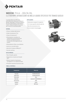
IMPIANTO ELETTRICO
ALTERNATORE - REGOLATORE "OUCATI"
The electrical system consists of the following:
• battery;
• starter motor with electromagnetic controls;
• generator-alternator, fitted on the rear part of the
engine shaft;
• pick-up;
• electronic box;
• ignition coil;
• electronic box condenser;
• voltage regulator;
• fuse box ( No.4, 15 Amp fuses) ;
• horn switch;
• starter solenoid;
• headlight;
• taillight;
• direction indicator lights;
• ignition switch;
• light switch;
• direction indicator lights control, horn button and
flasher;
• hazard warning lights switch;
• starter device;
• electric horn;
• Warning lights on instrument panel for: neutral
indicator (green), side lights on (green), oil pressure (red), main beam (blue), generator (red), fuel
reserve (red), direction indicators (green) .
24.2
AL TERNA TOR - REGULA TOR "DUCA T/"
Grafico intensita corrente di carica
Current charge intensity graph
27.00
24.00
21.00
•
~
•~
•
oj
c:i
oj
15.00
-c
12.00
"E
900
~
'"
/
18.00
I
v
-G/min.
/
V
6.00
3.00
0.00
0.0
1.0
2.0
3.0
4.0
5.0
6.0
TO
8.0
rp.rn.
Amp. D.C.
D.C. Amps
1000
1200
1500
2000
3000
4000
6000
8000
8.10
11.00
14.50
18.00
21 .50
23.00
24.50
25.00
9.0
giri x 1000 I Revs x 1000
COMMUTATORE/
IGNITION SWfrCH
1-----------r---SSEL~CCA_AVV<O~» L~5~m~m~q~.~~:;~==j1
CABLE SECTlON~ 2.5 sq.mm.
+
BAITERI"' , _
BATTERY 12V
ATTENZIONE!
L'eventuale inversione dei collegamenti danneggia in modo irreparabile iI regolatore.
WARNING
If connections are inverted the regulator will be
irreversibly damaged.
Accertarsi della perfetta efficienza del collegamento a massa del regolatore.
Check that the regulator earth connections are
efficient.
Possibili verifiche da effettuare sull'alternatore e
sui regolatore in caso cessi di ricaricarsi la batteria 0 che la tensione non venga pili regolata.
Possible checks to be carried out on the alternator or regulator if the battery fails to re-charge or
the power supply is no longer regulated.
Alternatore
A molore fermo scollegare i due cavi gialli del generalore dal reslo deli'impianto ed effettuare con un
ohmmelro i seguenti controlli:
Controllo isolamento avvolgimenti verso massa
Collegare un capo dell'ohmmetro ad uno dei due cavi
gialli e I'allro capo a massa (pacco lamellare).
Lo strum enlo deve indicare un valore superiore a
10MQ.
Alternator
With the engine switched off, disconnect the two
yellow generator cables from the rest of the system
and then carry out the following tests with a ohmmeter:
Check the winding isolation towards ground
Connect one connecting point of the ohmmeter to
one of the two yellow cables and the other connecting
point to ground (laminar pack).
Tile instrument should indicate a value above 10 MQ
29
Cantralla cantinuita avvalgimenti
Collegare I'ohmmetra ai capi dei due cavi gialli.
Lo strumento deve indicare un valore di 0.2-<-0.3 n.
Cantrallo tensione d 'uscita
Collegare un voltmetro in alternataportata 200 Volt ai
capi dei due cavi gialli.
Mettere in moto iI motore e verilicare che Ie tensioni
in uscita siano comprese nei valori riportati nella
seguente tabella:
Giri/min.
1000
3000
6000
r.p.m.
1000
Volt a.c.
~ 15
~ 40
~80
A.C. volts
~
Regalatore
II regolatore e tarato per mantenere la tensione di
batteria a valori compresi Ira i 14+14.6 Volt.
La lampada spia (accesa a motore spento, chiave
inserita) si spegne quando il generatore inizia a
caricare, (circa 700 giri)
Verifiche sui regolatore
Per il contrallo del regolatore non sana sufficienti Ie
normali attrezzature di officina, diamo comunque qui
di seguito alcune indicazioni su misure che servono
ad individuare un regolalore sicuramenle difettoso.
II regolatore e sicuramente difettoso se:
Dopo ave rio isolato dal reslo deli'impianlo presenla
corto circuito Ira massa (custodia alluminio) e uno
qualsiasi dei cavi d'uscita.
24.5
MOTORINO AVVIAMENTO "VALEO"
CARATTERISTICHE GENERAL!
Tensione
Potenza
Coppia a vuoto
Coppia a carico
Pignone
Rotazione lato pignone
Velocita
Corrente a vuoto
Corrente a carico
Peso
30
Check the winding continuity
Connect the two connecting points of the ohmmeter
to the two yellow cables.
The instrument should indicate a value of 0.2+0.3 n.
Check the voltage output
Connect an alternate 200 Volt capacity voltmeter to
the two yellow cables.
Start the engine and check that the voltage output is
included within the values indicated on the following
tables:
12V
1,2 Kw
11 Nm
4,5 Nm
Z=9 mod. 2,5
Antiorario
1750 giri/min.
600 A
230 A
2,8 Kg
15
3000
~
40
6000
~
BO
Regulator
The regulator has been calibrated in order to maintain
the battery voltage at a value between 14+ 14. 6 Volts.
The pilot light (illuminated when the engine is not
running, but the key is inserted) will switch off wilen
the generator begins to charge, (approx. 700 rp.m.)
Regulator checks
Normal work-shop tools are generally insufficient for
regulator checking, however, listed below are certain
operations that can be carried out in order to detect
regulators that are defective.
The regulator is certainly defective if:
After having isolated it from the rest of the system
short circuits can be detected between the ground
(aluminum casing) and any of the output cables.
24.5
STARTER MOTOR "VALEO"
GENERAL CHARACTERISTICS
Voltage
Power
No-load Torque
Torque under load
Pinion
Rotation, pinion side
Speed
No-load current
Current under load
Weight
12V
1,2Kw
11 Nm
4,5Nm
Z=9mod. 2,5
Anti-clockwise
1750 r.p.m.
600 A
230 A
2,BKg
24.6
ACCENSIONE ELETTRONICA
"MOTOPLAr'
24.6
ELECTRONIC IGNITION "MOTOPLA T"
Caratteristiche accensione
Accensione elettronica; la variazione di anticipo avviene elettronicamente.
• Anticipo iniziale (Iisso)
2°+3°
• Anticipo massimo (Iisso+elettronico)
34°+35°
Tralerro tra captatore e rotore:
mm 0,2+0,4
L'accensione di tipo elettronico non richiede pratica·
mente manutenzione.
Ignition characteristics
Electronic advance change.
• Initial advance (fixed)
2"+3"
• Max. advance (fixed+electronic)
34"+3S>
Air gap between pick·up and rotor:
mm 0,2+0,4
The electronic ignition requires almost no mainte·
nance.
Messa in fase (Iigg. 38 - 39)
II motore in lase quando con il cilindro destro al
.. P.M.S.", punto morto superiore, in lase di scoppio,
il bordo sinistro della bandierina .. A» del rotore di
accensione si trova circa a meta del sensore .. 8 ..
(cilindro destro) sui pick·up, identificabile dal cavo
nero. Nel caso questo non si verilichi, allentare Ie viti
.. C .. , e con un cacciavite agire sulla scanalatura "E ..
per fare ruotare la piastra porta pick·up.
In alternativa Ii possibile ruotare iI corpo esterno del
dispositivo di accensione allentando Ie due viti infe·
riori di tenuta.
Timing (figs. 38· 39)
The engine timing occours when, in the explosion
phase, with the R.H. cylinder in the T.O.C. (top dead
center), the LH. side of the ignition rotor flag ..A" is
positioned near the half of the sensor ..8" (R.H.
cylinder) on the pick·up, identifiable through the black
cable. If not, loosen the screww .. C", and, through a
screwdriver, act on the groove .. E. in order to rotate
the pick· up holder plate.
Otherwise, it is possible to rotate the ignition device
outer body by unscrewing the two lower screws.
e
NERO
BLACK
31
For a more accurate advance control, use a
stroboscopic gun.
With the engine at 4500 rpm, the mark 4 (max.
advance) on the engine flywheel (see fig. 39) must be
aligned with the reference 1 on the inspection hole
side.
The reference «0» on the flywheel indicates the
T. o. C. (RH cylinder).
The reference 2 on the flywheel indicates the fixed
advance.
Per un pill accurato controllo dell'anticipo, utilizzare
una pislola Slroboscopica.
Can motore ad un regime di 4500 giri/min. , iI segno
4 (anticipo massimo) sui volano molore , vedi fig. 39 ,
dovre. essere allineato can il riferimenlo «1» sui bordo
del foro di conlrollo.
II riferimento «0 » sui volano indica il P.M.S. (cilindro
deslro).
II segno «2» sui volano indica I'anticipo fisso.
ATTENZIONE!
Per non provoeare danneggiamento a"'impianto
di aeeensione elettroniea, osservare Ie seguenti
preeauzioni:
• in easo di smontaggio a rimontaggio della
batteria aeeertarsi ehe il eommutatore dl aeeensione sia in posizione OFF;
• non seo"egare la batteria eon motore in mota;
• aeeertarsi de "a perfetta effieienza dei eavi di
massa delle eentraline.
WARNING!
In order to prevent from damaging the electronic
Ignition system, note the following precautions:
• in case of battery disassembly or reassembly,
make sure the ignition switch is in OFF position;
• don't disconnect the battery when the engine
is on;
• control the perfect efficiency of electronic devices cables.
GRAFICO CURVA ANTICIPO ACCENSIONE
ELETTRONICA
ELECTRONIC IGNITION ADVANCE CURVE DIAGRAM
/
36F+=m~
/ ~
' ~Fl
/ /
34
/~
I
//1
30
28
26+- -1- --/- - - f-1,.
1<;,/__+
__+-_---1__-+__
.ILI
24
22+_ _
20
/ /
/
32
10
Battena-"1.1"
2\V'--:--=c±-_---1
Temp. a1biente 25"1r;__ _ .j
___ .
+ __-+~{-,
r1-j+--_
==--
1
-
Battery 1 V
Amb. (e"p. 25'C _
--
18
16
14
12
I----l--~ ----~---~~-~-~-~
10
if
8-
-
-
f/l
6
-
'Z/--;!!
2
o
1000
2000
3000
4000
5000
6000
GIRl MOTORE
ENGINE REVOLUTIONS
32
7000
I
BODO
9000
10000
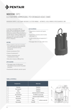
24.7
ACCENSIONE ELETTRONICA MAGNETI
MARELLI "DIGIPLEX"
Controllo messa in fase.
Per il controllo della fasatura operare come segue:
• Con motore al regime di 800+900 girii min. verifica·
re, con pistola stroboscopica, che I'accensione
awenga 8° prima del P.M.S.
• In caso di necessita possibile ridurre I'anticipo di
2° collegando tra di loro i due cavi «A" e «B" (fig.
e
44).
• Valore del traferro tra i 5 denti ricavati sui volano
motore ed il sensore: mm 0,3+0,8.
24.7
ELECTRONIC IGNITION MAGNETI
MARELLI "DIGIPLEX"
Checking of the timing.
As for the checking of the timing act as follows:
• At800+900rp.m. verify, by stroboscopic gun, that
the ignition takes place SO before of the T. D. C.
• If necessary, it is possible to reduce the spark
advance of2' joining the two cables «A» and «B"
between them, as shown in the drawing (fig. 44).
• Valve of the gap between the 5 teeth got on the
flywheel and the sensor: mm 0,3+0,8.
CenUalina etettronica
Electronic control unit
Volano malaTe
~!
-=R:.<.yw",h",e:::e:...'_ _
..----
c
Sensore
~
l~~~~r-..:,r~Aiaspirazione
due collettori di
tramile
ru'~-r-",I
\I
\I
1\
~~~~
':mTJ§ 1§]:Jilm'm-~rn
I --::--:--'--~~\
Traferro mm. 0,3+0,8
j
tubetto di collegamento
To intake manifold
by link pipe
Air gap O.~O.8 mm
Massa telaio
I '___G...
(O~~
Re1e (tipo auto) dedicate
impianio accensione:
Contatto riduzione d'anticipo
Advance adjustment wires
Remote switch:
lerminaJe
connesslone
35
+ Vbatt. salta chiave
86
massa
30
+ Vbatt. (sez. cava 2,5 mm2)
87/87b
Q
DigiplexlBAE50B
Sabina
Ignition coil
~o~
_ _ _:...o~
Per cillndro Sx.
For LH. cylinder
Sabina
Ignition coil
~O~_
_ _ -=O
Per cilindro Ox.
For R.H. cylinder
33
GRUPPO CAVI PER ACCENSIONE ELElTRONICA MAGNETI MARELLI "DIGIPLEX"
ELECTRONIC IGNITION CABLE ASSY MAGNETI MARELLI "DIGIPLEX"
Sabina cillndro sinistro
L.H. ignition coil
Babina cilindro destro
R.H. ignition coil
Contatta riduzione anticipo
Advance adjustment wires
Contagiri elettronico
Electronic revolution
counter
Sensore di lase
Timing sensor
Alimentazione
Feeding
Central ina elettronica
Electronic control unit
o
Rele
Remote switch
Prooisposizione inlerfaccia diagnostica
Schedvling to diagnostic instrument
34
+
Banena
Battery
SCHEMI ELETTRICI
ELECTRICAL SCHEMAS
35
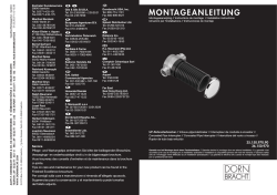
SCHEMA IMPIANTO ELETTRICO
25.1
LEGENDA SCHEMA IMPIANTO ELETIRICO
(con accensione elettronica " Motoplat")
1 Lampada luce abb. e anabb. 60/55 W
2 Lampada luce posizione anter. 4 W
3 Lampada spia indicat. direzione ds.
4 Lampada illuminazione tachimetro
5 Lampada illuminazione contagiri
6 Lampada spia indic. direzione sinis.
8 Lampada spia livello carburante
9 Lampada spia pressione olio
10 Lampada spia generatore
11 Lampada spia "folie"
12 Lampada spia luci posizione
13 Lampada spia luci abbagliante
14 Comm. inserim. simultaneo lampeggiatori
15 Indicatore direzione ant. destro
16 Interruttore stop freno anteriore
17 Commutatore d'accensione
18 Indicatore direzione ant. sinistro
19 Claxon bitonali
20 Disp. avv. arr. motore
21 Interruttore posizione "folie"
22 Interruttore pressione olio
23 Intermittenza (12 V 46W)
24 Dispositivo com.do: lud-claxon-indic. direz.
25 Can dele d'accensione
26 Bobine alta tensione
27 Centraline per acc. elettronica
28 Interruttore stop freno posteriore
29 Morsettiera portafusibili
30 Trasmettitore livello spia carburante
31 Regolatore di tensione (12V-25A)
32 Alternatore 14V - 25A
33 Interruttore cavalletto laterale
34 Batteria 12V - 24 Ah
35 Teleruttore avviamento
36 Motorino d'avviamento
37 Indicatore direz. poster. destro
38 Lamp. ilium. targa estop
39 Indicatore direz. poster. sinistro
40 Teleruttore claxon bitonali
41 Teleruttore a deviatore per cavalletto later.
42 Connet. AMP a 6 vie
43 Con net. Molex a 6 vie
44 Pick-up
45 Condensatore
46 Connetore AMP 4 vie
36
II
25.1
WIRING DIAGRAM
ELECTRIC SYSTEM SCHEME LEGEND
(with electronic ignition "Motoplat")
1 Bulb, main/dipped beam 60/55 W
2 Bulb, front sidelights 4 W
3 Bulb, r/h direction indicator warning light
4 Bulb speedometer light
5 Bulb rev. counter light
6 Bulb, I/h direction indicator warning light
8 Bulb fuel level warning light
9 Bulb, oil pressure warning light
10 Bulb, generator warning light
11 Bulb, neutral warning light
12 Bulb, sidelight warning light
13 Bulb, main beam warning light
14 Emergency flasher switch
15 R.H. front direction indicator
16 Front brake stop switch
17 Starter switch
18 UH front direction indicator
19 Two-note horn
20 Control switch: start/stop engine
21 Neutral position switch
22 Oil pressure switch
23 Blinker unit (12 V 46W)
24 Control switch: start/stop engine
25 Spark plugs
26 H. T. coil
27 Electronic ignition unit
28 Rear brake stop switch
29 Fuse terminal board
30 Low fuel level warning sensor
31 H. T. coil (12V-25A)
32 Alternator 14 V - 25A
33 Side stand microsWitc
34 Battery 12V - 24 Ah
35 Starter solenoid
36 Voltage regulator
37 R/H rear direction indicator
38 Bulb, number plate and stop light
39 UH rear direction indicator
40 Two-note hom switch
41 Solenoid for side stand
42 Connector AMP 6-way
43 Connector Molex 6-way
44 Pick-up
45 Capacitor
46 Connector AMP 4-way
r;EE!f.\c'lm
~':'"
~I
..
t" /!r,\,1 ,,-"-+-
( o,
.. - I
~
"" l .. !MI!1:-
CUMMUI.l!(lIlE
,,~
'
",
\
, ,Ie.:;-tG
e ,to;t:-v\
r~
,--=--
1
@
Il
;,
,
;~~
i
~
,
i l;
@
;·'0- )
I-
~I-'
~
L
[;J
',I
i~
-
---
l
1.
-
.,
I~
.,
@
Aranda ""
Azzurra '"
Bianco '"
GIa llo =
Grigio ;;
Marrone "'"
Nero =
Rosa =
Rosso =
Verde ;;
Viola =
Bianco-Azzurro ""
Bianco-Giano -=0
Bianco-Marrone ;Bianco-Nero =Blsu-Nero =
Giallo-Nero",
Nero-Grigio ;;
Rosso-Bianco '"
Rosso-aleu ""
Rosso-GiaHo ""
Rosso-Nero""
Rosso- Verde '"
Verde-Grig lo =
Verde-Nero =
-
?
,
:r
(0
@@----,
I
.... "
,!
•.,,
• " .,.
7]'
It:8£.-./
I E)
(0
,( I \,,,
~J)l ~7
0
-~
~ i-
--=
,0
:1
K::D
.,,-
".
,
, " ",
11o, ,,,,,
,
l..!!.r.~"t"_
r
,',- '
-,
,,
.
Violet
White-Ught blue
White-Yellow
While-Brown
White-Black
Blue-Black
Yellow-Black
Black-Grey
Red-Wllite
Red·Blue
Red- Yellow
Red-Black
Red-Green
Green-Grey
Green-Black
~)
~~,~~
@
JO
Orange
Ught blue
White
Yellow
Grey
Brown
Black
Pink
Red
Green
,,
J @)
0
C
"
..._.
(" ~ "o
~"
\
@)
r ,.
_N ,
,
,' ,,
1 . .. " 1tC
: '0
I
I 'I
L_• .!
)
RO~§D "'~ 'O
.,
.,.
,
,....
(J~
....,
--
@
r f-~
If-
~o
] ,,,,,,v,C.'olio
"
,
'"'
®
,
,
'--®
---
.-
1.1:;= pi
~
Q-i-c
It-
3
®
....
o
®
•
.,
~~ ,,>
.u. . . .
lI ou,,_oj ~ 'D
GE "
1\--
(" Olio
r. .a ll"
®
" " "
""
~~
....
/~"
)Olr- n
~~ g'E!7 ./,.
:!:!
0 0
.
1...,-
~O§~
E-
,-
q<K~U
11'
' 0 ----1"
1-' ,---'
1~1
~
\,
@
®
:'~'lm.
'
~/:::
" l
IT
. ~jY "
~
,,'~
"0
J
t'-Ul a lCilit
,j
V~
r0"!)
,-
'""C( "..,~
,,",,2., \\;t-
I",..
I.,.,
.T
~
~ '~~~~
(:3)
~~.
.,
~
f
o iG9
f-LI
@
P
,,,
,.
,
G I'"
@r.::-;...
,
\::.!7
/
__ J
,
~~
-.,
.,
f- c-
,,
I
,"'-'
-
,
...
.
i
ill ~
I
-
~
I 10
"'''
r--
I:.)
1/1 ~
I"
\
~~
IiI -
~/Ci}~
;,
Arancio = Orange
Azzurro
=
\
f ')
~7
-~
~
....
0;
@
I(
~
I""
~0ir
~
,
,
II
~~
L-
,
,
r:;;;;
J---J
.
9~(,
0€!
I ... ~
," ,
~
I
~
L,g"t blue
I
Giallo '" Yellow
=
!
Grey
-
"'
Bianco .,. White
Griglo
~
.
Ii
;
;
I
I~
Marrone "" Brown
Nero
=
Black
Rosa ,. Pink
Rosso -= Red
"-
Verde ", Oreen
~
(@~
Viola = Violet
-
9 lanco-Azzurro '" Whire-Light blue
Bianco-Giallo '" White-Yellow
91 anco-Marrone
= White-Brown
Bianco-Nero = While-Black
Bleu ·Nero ., Blue-Black
Giallo-Nero
=
Yellow-Black
Nero-Grigio '" Black-Grey
Ros!'io-8ianco '" Red- White
Aosso-8leu
D
=
Red·Blue
Rosso-Giallo ", Red-Yellow
Rosso- Nero ;: Red-Black
Rosso-Verde "" Red-Green
Verde-Grigio = Green-Grey
Verde-Nero = Green-Black
@
~
•.
@
::::;::
~}-;I
~
" c - I"
" ' ~I )
"
-~
, ~
11
~
-f
"J.'
I~~~: !~n~t::~.~,;~~L6A~-'- ·-·-· ~~ t' t~-'-l
__ ~'
~ .. ..~" ....... II
I
~[{ l +
I·~\~' ...
,._.,_._....
,, ".....
,
,
/
,"
....,.,"".""."
.... ,.,.....
.'
,...! ,_ ......."
.... " .,-,
a
/
I
I
1
""""'"
•
'.
," , t" ,.. , • .,,,
I , ."" ,
.~
...
,....."........,'.....'" ",
"
."" "., .. " . • " .• ,,. " " - ,
, , - • • - . """"'" " " ,,, . . ,,, ,, " ""
ql
;::~': ::7:L'~ ,!',~'. ::::~: ::;.'~:~~ .
>........
. ,.;.:,'.:,.:.:.~:;.,:':.:'::,.:.:"'"
, ~ ~,:,:,':,',:,:.',
" " " ",,"" .... ...... "., ' "''
I ...~ ..":::.":":~~.;',:,::';:i';~~
.;;:::.
LJ
,' ®
._ .... .
_
' ' ' '''''
]1
"... "", I'""""'
Q ' ' ' '',. . . . .
¥"" ""
.....
"'1<
~
'." '1
1
~
" " ....
'!'
()
~
" . ,,..,~
.
. " .. r.."
" '. ', ,. ',.....".',",'. . .,"••".' - '
•• •••~;"1"
'
~
ft
/
.•.','~':::. •~'
..."". ......
""\
..". "".' K.. ....,. ,... ~~ " . ' h .
"""",,·,>t' · .. ~ ,
0
0
~"-....
---------- __ . __ . -
1'-. . J
,
.
1
0
I'
•
.
i
..
,
.W ,,,
••
@
-
'.
--.
, • ,,
. ., ®
t-
v.,
..., b--
~
t.=
I
0
_ . - _ _ ...J
'M
,
,, '
1
r,",, ·!'" ' .
::~ ;::~:';:~;~i~::':·~:::'~~~~
.
,. . , . . . .
I
0
" .~.
t ,
1
:;;:';";;'::,':-; ; ;:',';"
,~." ' ' 'l
"'
.."",,
....... .......
'" .. ,. . . . . .
,
@
,"~M"
.~
'" ,.....,-"
""~' . . ... . ... ~
11 " .. . . .......... . . , . " , . .
.,- _~
"',,.. .
:;-':'i;"· ,"
«o~\
. , I,. , .-f .....,, '
.~'.I." .'\ ..L ~ r~
"
~,-.,." ..- - - - -)
I "":::;::;;.;.,'".""" ".... "..,
I
--.::r:J3
~::.'.:::::.,
(i) .. .. .. " •• • " '" "" " ' . '"
1
,I
t"" '~' _
®
"
lO
~ .r---l
86
tc~I
" " "
@
_N
•
I
© Copyright 2026 Paperzz