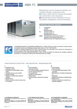
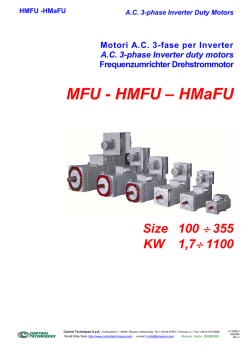
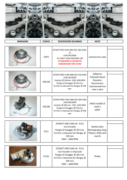
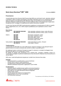
WI
WMI
1.0 RIDUTTORI UNIVERSALI A VITE SENZA FINE
WORM GEARBOXES
SCHNECKENGETRIEBE
Pag.
Page
Seite
1.2
Designazione
Designation
Bezeichnungen
I2
1.4
Lubrificazione
Lubrication
Schmierung
I4
1.5
Carichi radiali e assiali
Axial and overhung loads
Radiale und Axiale Belastungen
I6
1.6
Prestazioni riduttori
Gearboxes performances
Leistungen der Getriebe
I9
1.8
Dimensioni
Dimensions
Abmessungen
I13
1.9
Accessori braccio di rezione
Accessories torque arm
Zubehör Drehmomentstütze
I17
1.10
Accessori alberi lenti
Accessories output shafts
Zubehör Abtriebswellen
I17
1.11
Cappellotto
Cover
Deckel
I18
WMI
WI
CT16IGBD2
I1
I
1.2 Designazione
Grandezza
Size
Größe
1.2 Designation
Versione
Version
Ausführung
ir
Tipo
Type
Typ
IEC
Grandezza
Size
Gröe
1.2 Bezeichnung
Lunghezza
Lenght
[*1]
[*2]
Designazione Motori
Designation Motors
Bezeichnung Motoren
[*3]
CT18IGBD1
Länge
63 (B5)
WMI 40 1/20 PAM 63
(B5)
63 (B14)
....
WMI
25
30
40
50
63
75
90
110
130
150
-
T
FA
FB
vedi
tabelle
see tables
siehe
Tabellen
56
A
TA
....
....
....
315
ML
ø19
B
—
ø24
(standard)
WMI 40 1/20 T 56 A 4 B5
ø28
FC
ø35
ø38
SIN
WI
WI 40 1/20
Nessuna indicazione =
bisporgenza;
B = vite con bisporgenza.
• [*1] Doppelseitige Schneckenwelle
• [*1] Double Extended Input Shaft
• [*1] Bisporgenza Vite:
vite
Keine Angabe = Schnecken ohne
doppeltes Wellenende
B = Schnecke mit doppeltem
Wellenende
No indications = input shaft without
double extension;
B = double extended input shaft.
senza
• [*2] Wellendurchmesser:
• [*2] Shaft Diameter:
• [*2] Diametro albero:
Keine Angabe =
Standard-Bohrungsdurchmesser
Optionaler Bohrungsdurchmesser =
(siehe Tabelle).
No indications = standard hole diameter;
Nessuna indicazione = diametro foro
standard;
diametro foro opzionale = (vedi
tabella).
optional hole diameter = (see table).
Grandezza - Size - Größe
WI - WMI
25
30
40
50
63
75
90
110
130
150
Standard
11
14
18
25
25
28
35
42
45
50
Optional
-
-
19
24
28
35
38
-
-
-
D H7
• [*3] Lato flangia uscita:
Nessuna indicazione = flangia uscita con
montaggio destro (flange dal lato come
indicato nelle figure del catalogo);
SIN = flange uscita con montaggio
sinistro (flange dal lato opposto alle
figure indicate a catalogo).
I2
• [*8] Mounting position output side:
No indication (standard) = output flange
on right side (like indicated in the figures);
SIN = output flange on left side (flanges
on the opposite side like indicated in
figures).
• [*8] Montageseite Abtriebsflansch:
Keine Angabe (Standard) = Abtriebsflansch rechts (wie in den Abbildungen
dargestellt)
SIN = Abtriebsflansch links (gegenüber
der Position in den Katalogabbildungen).
CT16IGBD2
1.2 Designazione
1.2 Designation
ALTRE SPECIFICHE:
FURTHER SPECIFICATION:
WEITERE SPEZIFIKATIONEN:
•
•
•
posizione della morsettiera del motore se
diversa da quella standard (1)
terminal board box position if different from
standard (1)
1.2 Bezeichnung
Stellung des Klemmenkastens des Motors,
falls diese von der Standard- Ausführung
abweicht (1)
Senso di rotazione standard
Standard direction of rotation
Drehrichtung Standard
I
WMI
-
WMI
FA-FB-FC
ACCESSORI
ACCESSORIES
ZUBEHOR
•
•
•
•
•
•
alberi lenti
braccio di reazione
CT16IGBD2
output shafts
Torque arm
Abtriebswellen
Drehmomentstütze
I3
OIL
1.4 Lubrificazione
1.4 Lubrication
1.4 Schmierung
Lubrificazione riduttori
Gearboxes lubrication
Schmierung Getriebes
WI - WMI
Generalità
Si consiglia l'uso di oli a base sintetica.
Vedere a tale proposito le indicazioni
riportate nel capitolo A, paragrafo1.6 e 1.2..
Nella tab. 2.2.1 sono riportati i quantitativi di
olio necessari per il corretto funzionamento
dei riduttori.
General information
The use of synthetic oil is recommended.
(see details in Chapter A, paragraph 1.6
and 1.2). Tab. 2.2.1 shows the quantities of
oil required for correct worm gearbox
performance.
Prescrizioni in fase di ordine e stato di
fornitura
I riduttori sono forniti completi di olio
sintetico di viscosità ISO 320.
Per questi riduttori non è necessario
specificare la posizione di montaggio.
Ordering phase requirements and state
of supply
Worm gearboxes sizes 40, 50, 63, 75, and
85 come supplied with ISO 320 viscosity
synthetic oil.
It is not necessary to specify mounting
positions with these worm gearboxes.
I riduttori delle grandezze 110, 130, 150
sono forniti predisposti per lubrificazione ad
olio ma privi di lubrificante il quale potrà
essere fornito a richiesta. Per questi
riduttori è necessario specificare la
posizione di montaggio.
Size 110, 130, 150 worm gearboxes require
oil lubrication but are supplied without
lubricant that can be requested separately.
It is necessary to specify the mounting
position for these worm gearboxes.
Die Getriebe in den Baugrößen 110, 130,
15080 sind bei der Lieferung für die
Ölschmierung vorbereitet, enthalten jedoch
kein Schmiermittel. Dieses kann auf
Anfrage geliefert werden. Für diese
Getriebe muss die Einbaulage verbindlich
angegeben werden.
Posizioni di montaggio WI-WMI
Mounting positions WI-WMI
Montagepositionen WI-WMI
Allgemeines
Der Einsatz von synthetischem Öl wird
empfohlen. (Siehe diesbezüglich die
Hinweise im Kapitel A, abschnitt 1.6 und
1.2.
In der Tabelle Tab. 2.2.1 werden die
erforderlichen Ölfüllmengen für einen störungsfreien Betrieb der Getriebe aufgeführt.
Vorgaben für die bestellung und den
lieferzustand
Die Getriebe in den Baugrößen werden
komplett mit Synthetiköl mit einer Viskosität
ISO 320 geliefert. Für diese Getriebe
muss die Einbaulage nicht angegeben
werden.
WI - WMI
M1
M6
M3
M4
1
1
1
1
M5
M2
1
M
1
1
M4 5
M
I4
Z4
CT16IGBD2
Tab. 2.2.1
WI-WMI
Quantità di lubrificante / Lubricant Quantity / Schmiermittelmenge (kg)
Posizioni di montaggio
Mounting Positions
Montagepositionen
M1
M2
M3
M4
M5
M6
Posizione di
n°. tappi olio
montaggio
No. of plugs
Mounting position
Anzahl Schrauben
Montageposition
Stato di fornitura
State of supply
Lieferzustand
25
0.02
1
30
0.04
1
40
0.08
50
0.150
1
63
0.300
1
75
0.550
1
90
1.000
1
Riduttori forniti completi di lubrificante sintetico
Gearboxes supplied with synthetic oil
Getriebe werden mit synthetischem Öl geliefert
110
3.000
2.200
3.000
2.200
2.500
130
4.500
3.300
4.500
3.300
3.500
150
7.000
5.100
7.000
5.100
5.400
1
3
Riduttori predisposti per lubrificazione ad olio
Gearboxes supplied ready for oil lubrication
Getriebe sind für Ölschmierung vorgerüstet
3
3
Non é necessaria
It is not necessary
Nicht Erforderlich
I
Necessaria
Necessary
Erforderlich
(1) Indicative quantities, check the oil sight glass during
filling.
(1) Richtungsweisende Mengen, bei der Auffüllung auf
das Füllstand-Kontrollfenster Bezug nehmen.
A) Se in fase d’ordine la posizione di montaggio è omessa, il riduttore verrà fornito
con i tappi predisposti per la posizione
M1.
A) If the mounting position is not specified
in the order, the worm gearbox supplied
will have plugs pre-arranged for position
M1.
A) Hinweis: Sollte in der Auftragsphase die
Einbaulage nicht angegeben werden,
wird das Getriebe mit Stopfen für die
Einbaulage M1.
B) Il tappo di sfiato è allegato solo nei
riduttori che hanno più di un tappo
olio.
B) A breather plug is supplied only with
worm gearboxes that have more than
one oil plug.
C) The gearboxes that need a specific
assembling position have the indication
of it on the label of the gearbox.
B) Der Entlüftungsstopfen ist lediglich bei
den Getrieben vorhanden, die über mehr
als einen Ölfüllstopfen verfügen.
C) In den Getrieben in dem man die
Montage Position angeben soll, findet
man die angefragte Position auf dem
Typenschild des Getriebes.
(1) Quantità indicative; durante il riempimento attenersi
alla spia di livello.
Carico / Breather plug / Nachfüllen - Entlüftung
Livello / Level plug / Pegel
Scarico / Drain plug / Auslauf
C) Nei riduttori dove è necessario
specificare
la
posizione
di
montaggio, la posizione richiesta è
indicata nella targhetta del riduttore.
CT16IGBD2
I5
1.5 Carichi radiali e assiali
1.5 Axial and overhung loads
Il carico radiale sull’albero si calcola con la seguente formula:
The radial load on the shaft is calculated with the following formula:
Fre
(N)
Carico radiale risultante
M
(Nm)
Momento torcente sull’albero
D
(mm)
Diametro dell’elemento di trasmissione montato sull’albero
Fr
(N)
Valore di carico radiale massimo ammesso (ved. tabelle relative)
Fre
(N)
Resulting radial load
M
(Nm)
Torque on the shaft
D
(mm)
Diameter of the transmission member mounted on the shaft
Fr
(N)
Value of the maximum admitted radial load (see relative tables)
fz = 1,1
1,4
1,7
2,5
fz = 1,1
1,4
1,7
2,5
pignone dentato
ruota per catena
puleggia a gola
puleggia piana
1.5 Radiale und Axiale
Belastungen
gear pinion
chain wheel
v-pulley
flat pulley
a , b , x = valori riportati nelle tabelle
Zahnrad
Rad für Kette
Flanschscheibe
Flachriemenscheibe
Wenn die Querkraft nicht auf die Mitte der Welle bezogen ist, ist die
effektive Kraft durch nachstehende Formel zu berechnen:
a , b , x: siehe Tafeln
a , b , x = values given in the tables
ALBERI IN USCITA
Fre
(N)
resultierende Querkraft
M
(Nm)
Wellendrehmoment
D
(mm)
Durchmesser des an der Welle montierten Antriebselements
Fr
(N)
max. zul. Querkraft (siehe entspr. Tafel)
fz = 1,1
1,4
1,7
2,5
When the resulting radial load is not applied on the centre line of the
shaft it is necessary to calculate the effective load with the following
formula:
Quando il carico radiale risultante non è applicato sulla mezzeria
dell’albero occorre calcolare quello effettivo con la seguente formula:
Die Querbelastung (Querkraft) auf der Welle wird durch
nachstehende Formel berechnet:
OUTPUT SHAFTS
ABTRIEBSWELLEN
Frx
Fr
Fa
L/2
L
Fr (N)
WI
WMI
25
30
40
50
63
75
90
110
130
150
a
b
Fr2 max
50
38
1350
65
50
1830
84
64
3490
101
76
4840
120
95
6270
131
101
7380
162
122
8180
176
136
12000
188
148
13500
215
174
18000
2
ALBERI IN ENTRATA
INPUT SHAFTS
ANTRIEBSWELLEN
X
Frx
Fr
L/2
L
WI
a
b
Fr1 max
I6
Fr (N)
1
30
86
76
210
40
106
94.5
350
50
129
114
490
63
159
139
700
75
192
167
980
90
227
202
1270
110
266
236
1700
130
314
274
2100
150
350
310
2800
CT16IGBD2
1.5 Carichi radiali e assiali
1.5 Axial and overhung loads
1.5 Radiale und Axiale
Belastungen
Valore di carico radiale massimo
ammesso
Value of the maximum admitted
radial load
Max. zul. Querkraft
WMI 25
n1 = 2800
Fr1
Fr2
ir
N
7.5
10
15
20
30
40
50
60
-
N
-
WI-WMI 30
n1 = 1400
Fr1
Fr2
N
N
-
503
553
633
697
798
878
946
1006
-
n1 = 900
Fr1
Fr2
N
N
n1 = 500
Fr1
Fr2
N
-
ir
N
7.5
10
15
20
25
30
40
50
60
80
100
-
WI-WMI 40
n1 = 2800
Fr1
Fr2
ir
7.5
10
15
20
25
30
40
50
60
80
100
n1 = 1400
Fr1
Fr2
n1 = 900
Fr1
Fr2
n1 = 500
Fr1
Fr2
N
N
N
N
N
N
N
N
233
272
291
204
236
350
350
350
350
350
350
1044
1149
1315
1447
1559
1657
1824
1964
2087
2298
2475
294
331
331
350
350
350
350
350
350
350
350
1315
1447
1657
1824
1964
2087
2298
2475
2630
2895
3118
319
350
350
350
350
350
350
350
350
350
350
1524
1677
1920
2113
2276
2419
2662
2868
3047
3354
3490
350
350
350
350
350
350
350
350
350
350
350
1853
2040
2335
2570
2769
2942
3238
3488
3490
3490
3490
n1 = 2800
Fr1
Fr2
7.5
10
15
20
25
30
40
50
60
80
100
n1 = 900
Fr1
Fr2
n1 = 500
Fr1
Fr2
N
N
N
N
N
N
N
N
125
140
140
146
210
210
127
128
126
130
-
542
597
683
752
810
861
948
1021
1085
1194
-
150
169
169
190
210
210
210
210
210
210
-
683
752
861
948
1021
1085
1194
1286
1367
1504
-
175
197
197
210
210
210
210
210
210
210
-
792
871
997
1098
1183
1257
1383
1490
1583
1743
-
210
210
210
210
210
210
210
210
210
210
-
963
1060
1213
1336
1439
1529
1683
1813
1830
1830
-
ir
7.5
10
15
20
25
30
40
50
60
80
100
n1 = 2800
Fr1
Fr2
n1 = 1400
Fr1
Fr2
n1 = 900
Fr1
Fr2
n1 = 500
Fr1
Fr2
N
N
N
N
N
N
N
N
324
378
399
417
482
490
490
490
490
490
490
1433
1577
1805
1987
2140
2274
2503
2696
2865
3153
3397
401
490
490
490
490
490
490
490
490
490
490
1805
1987
2274
2503
2696
2865
3153
3397
3610
3973
4280
448
490
490
490
490
490
490
490
490
490
490
2091
2302
2635
2900
3124
3320
3654
3936
4183
4604
4840
490
490
490
490
490
490
490
490
490
490
490
2544
2800
3205
3528
3800
4038
4445
4788
4840
4840
4840
WI-WMI 75
n1 = 1400
Fr1
Fr2
n1 = 900
Fr1
Fr2
n1 = 500
Fr1
Fr2
N
N
N
N
N
N
N
N
1873
2061
2359
2597
2797
2973
3272
3524
3745
4122
4440
395
463
492
538
593
700
700
700
700
700
700
2359
2597
2973
3272
3524
3745
4122
4440
4719
5193
5595
500
571
615
667
700
700
700
700
700
700
700
2734
3009
3444
3791
4084
4339
4776
5145
5467
6018
6270
580
661
670
700
700
700
700
700
700
700
700
700
700
700
700
700
700
700
700
700
700
700
3325
3660
4190
4611
4967
5279
5810
6259
6270
6270
6270
CT16IGBD2
n1 = 1400
Fr1
Fr2
WI-WMI 50
WI-WMI 63
ir
n1 = 2800
Fr1
Fr2
ir
7.5
10
15
20
25
30
40
50
60
80
100
n1 = 2800
Fr1
Fr2
n1 = 1400
Fr1
Fr2
n1 = 900
Fr1
Fr2
n1 = 500
Fr1
Fr2
N
N
N
N
N
N
N
N
560
703
727
872
980
980
980
980
980
980
980
2210
2433
2785
3065
3302
3509
3862
4160
4421
4865
5241
700
830
851
980
980
980
980
980
980
980
980
2785
3065
3509
3862
4160
4421
4865
5241
5569
6130
6603
810
975
980
980
980
980
980
980
980
980
980
3227
3551
4065
4474
4820
5122
5637
6073
6453
7103
7380
980
980
980
980
980
980
980
980
980
980
980
3925
4320
4945
5443
5863
6231
6858
7380
7380
7380
7380
I7
I
1.5 Carichi radiali e assiali
1.5 Axial and overhung loads
1.5 Radiale und Axiale
Belastungen
Valore di carico radiale massimo
ammesso
Value of the maximum admitted
radial load
Max. zul. Querkraft
WI-WMI 90
ir
7.5
10
15
20
25
30
40
50
60
80
100
n1 = 2800
Fr2
Fr1
WI-WMI 110
n1 = 1400
Fr1
Fr2
n1 = 900
Fr1
Fr2
n1 = 500
Fr1
Fr2
N
N
N
N
N
N
N
N
715
900
1034
1120
1270
1270
1270
1270
1270
1270
1270
2446
2692
3081
3391
3653
3882
4273
4603
4891
5383
5799
900
1082
1257
1270
1270
1270
1270
1270
1270
1270
1270
3081
3391
3882
4273
4603
4891
5383
5799
6163
6783
7306
1040
1270
1270
1270
1270
1270
1270
1270
1270
1270
1270
3570
3929
4498
4951
5333
5667
6238
6719
7140
7859
8180
1270
1270
1270
1270
1270
1270
1270
1270
1270
1270
1270
4343
4780
5472
6022
6487
6894
7588
8174
8180
8180
8180
ir
7.5
10
15
20
25
30
40
50
60
80
100
WI-WMI 130
ir
7.5
10
15
20
25
30
40
50
60
80
100
I8
n1 = 2800
Fr1
Fr2
N
N
1190
1493
1725
1912
2100
2100
2100
2100
2100
2100
2100
4042
4449
5092
5605
6038
6416
7062
7607
8084
8897
9584
n1 = 1400
Fr1
Fr2
N
N
N
N
950
1194
1337
1485
1700
1700
1700
1700
1700
1700
1700
3090
3401
3893
4285
4616
4905
5399
5816
6181
6803
7328
1200
1463
1604
1700
1700
1700
1700
1700
1700
1700
1700
3893
4285
4905
5399
5816
6181
6803
7328
7787
8571
9232
n1 = 900
Fr1
Fr2
N
N
1390 4511
1700 4965
1700 5684
1700 6256
1700 6739
1700 7161
1700 7882
1700 8491
1700 9023
1700 9931
1700 10320
n1 = 500
Fr1
Fr2
N
N
1700
1700
1700
1700
1700
1700
1700
1700
1700
1700
1700
5488
6040
6914
7610
8198
8711
9588
10320
10320
10320
10320
WI-WMI 150
n1 = 1400
Fr1
Fr2
N
n1 = 2800
Fr2
Fr1
N
1500 5092
1845 5605
2070 6416
2100 7062
2100 7607
2100 8084
2100 8897
2100 9584
2100 10185
2100 11210
2100 12076
n1 = 900
Fr1
Fr2
n1 = 500
Fr1
Fr2
N
N
N
N
1740
2100
2100
2100
2100
2100
2100
2100
2100
2100
2100
5901
6494
7434
8182
8814
9366
10309
11105
11801
12989
13500
2100
2100
2100
2100
2100
2100
2100
2100
2100
2100
2100
7178
7900
9043
9953
10722
11394
12540
13500
13500
13500
13500
ir
n1 = 2800
Fr1
Fr2
N
7.5
10
15
20
25
30
40
50
60
80
100
N
-
n1 = 1400
Fr1
Fr2
N
N
1950
2267
2285
2674
2800
2800
2800
2800
2800
2800
2800
6962
7663
8771
9654
10400
11051
12163
13103
13924
15325
16508
n1 = 900
Fr1
Fr2
N
N
-
n1 = 500
Fr1
Fr2
N
N
-
CT16IGBD2
1.6 Prestazioni riduttori WI
1.6 WI Gearboxes performances
1.6 Leistungen der WI-Getriebe
WMI 25
0.7
-1
n1 = 2800 min
ir
-1
-1
n1 = 1400 min
-1
n1 = 900 min
n1 = 500 min
n2
T2M
P
n2
T2M
P
n2
T2M
P
n2
T2M
P
min-1
Nm
kW
min-1
Nm
kW
min-1
Nm
kW
min-1
Nm
kW
186.7
140
93.3
70
46.7
35
28
23.3
-
11
12
12.3
12.4
13.3
12
11
10
-
0.25
0.21
0.15
0.12
0.08
0.08
0.055
0.04
-
7.5
10
15
20
30
40
50
60
-
-
-
-
IEC
56
I
WI 30
1.2
-1
n1 = 2800 min
ir
7.5
10
15
20
25
30
40
50
60
80
-
-1
-1
n1 = 1400 min
-1
n1 = 900 min
n1 = 500 min
n2
T2M
P
n2
T2M
P
n2
T2M
P
n2
T2M
P
min-1
Nm
kW
min-1
Nm
kW
min-1
Nm
kW
min-1
Nm
kW
373.3
280
186.7
140
112
93.3
70
56
46.7
35
-
13
13
13
12
15
15
14
12
12
11
-
0.58
0.45
0.31
0.23
0.25
0.21
0.16
0.12
0.10
0.08
-
186.7
140
93.3
70
56
46.7
35
28
23.3
17.5
-
18
18
18
18
20
20
18
17
16
12
-
0.41
0.32
0.23
0.18
0.18
0.15
0.11
0.09
0.08
0.05
-
120
90
60
45
36
30
22.5
18
15
11.3
-
20
20
20
19
23
21
21
19
18
14
-
0.30
0.24
0.17
0.13
0.14
0.11
0.09
0.07
0.06
0.04
-
66.7
50
33.3
25
20
16.7
12.5
10
8.3
6.3
-
24
24
24
23
29
26
24
22
20
17
-
0.21
0.16
0.12
0.09
0.10
0.08
0.06
0.05
0.04
0.03
-
IEC
56-63
WI 40
2.3
-1
n1 = 2800 min
ir
7.5
10
15
20
25
30
40
50
60
80
100
-1
-1
n1 = 1400 min
-1
n1 = 900 min
n1 = 500 min
n2
T2M
P
n2
T2M
P
n2
T2M
P
n2
T2M
P
min-1
Nm
kW
min-1
Nm
kW
min-1
Nm
kW
min-1
Nm
kW
373.3
280
186.7
140
112
93.3
70
56
46.7
35
28
27
30
31
29
28
34
31
30
27
25
22
1.20
1.00
0.72
0.52
0.42
0.44
0.32
0.26
0.21
0.16
0.12
186.7
140
93.3
70
56
46.7
35
28
23.3
17.5
14
40
40
39
39
38
44
41
37
35
33
29
0.90
0.69
0.48
0.37
0.30
0.31
0.23
0.18
0.15
0.12
0.09
120
90
60
45
36
30
22.5
18
15
11.3
9
43
44
45
44
44
48
44
43
38
37
33
0.65
0.50
0.36
0.28
0.23
0.23
0.17
0.14
0.11
0.09
0.07
66.7
50
33.3
25
20
16.7
12.5
10
8.3
6.3
5.0
53
53
56
52
49
58
53
52
46
40
38
0.45
0.35
0.26
0.19
0.15
0.16
0.12
0.10
0.08
0.06
0.05
IEC
56-63-71
WI 50
3.5
-1
n1 = 2800 min
ir
7.5
10
15
20
25
30
40
50
60
80
100
CT16IGBD2
-1
-1
n1 = 1400 min
-1
n1 = 900 min
n1 = 500 min
n2
T2M
P
n2
T2M
P
n2
T2M
P
n2
T2M
P
min-1
Nm
kW
min-1
Nm
kW
min-1
Nm
kW
min-1
Nm
kW
373.3
280
186.7
140
112
93.3
70
56
46.7
35
28
52
53
57
53
51
65
59
53
50
45
40
2.3
1.8
1.3
0.95
0.75
0.82
0.59
0.45
0.37
0.27
0.21
186.7
140
93.3
70
56
46.7
35
28
23.3
17.5
14
71
70
73
72
69
83
77
73
68
64
52
1.6
1.2
0.88
0.68
0.54
0.57
0.42
0.34
0.28
0.22
0.16
120
90
60
45
36
30
22.5
18
15
11.3
9
81
83
84
76
76
91
83
78
74
66
56
1.2
0.94
0.67
0.48
0.39
0.42
0.31
0.25
0.21
0.16
0.12
66.7
50
33.3
25
20
16.7
12.5
10
8.3
6.3
5.0
102
104
102
92
94
106
99
89
82
75
69
0.86
0.67
0.47
0.33
0.28
0.29
0.22
0.17
0.14
0.11
0.09
IEC
63-71-80
I9
1.6 Prestazioni riduttori WI
1.6 WI Gearboxes performances
1.6 Leistungen der WI-Getriebe
WI 63
6.2
-1
n1 = 2800 min
ir
7.5
10
15
20
25
30
40
50
60
80
100
-1
-1
n1 = 1400 min
-1
n1 = 900 min
n1 = 500 min
n2
T2M
P
n2
T2M
P
n2
T2M
P
n2
T2M
P
min-1
Nm
kW
min-1
Nm
kW
min-1
Nm
kW
min-1
Nm
kW
373.3
280
186.7
140
112
93.3
70
56
46.7
35
28
92
96
101
97
91
120
113
102
96
86
74
4.0
3.2
2.3
1.7
1.3
1.5
1.1
0.83
0.68
0.49
0.37
186.7
140
93.3
70
56
46.7
35
28
23.3
17.5
14
126
129
134
131
131
164
143
133
130
119
118
2.8
2.2
1.6
1.2
1.0
1.1
0.76
0.60
0.51
0.39
0.34
120
90
60
45
36
30
22.5
18
15
11.3
9
151
152
153
149
135
176
160
146
137
127
125
2.2
1.7
1.2
0.91
0.69
0.79
0.58
0.45
0.37
0.29
0.25
66.7
50
33.3
25
20
16.7
12.5
10
8.3
6.3
5.0
180
188
188
178
163
204
186
174
162
138
131
1.5
1.2
0.85
0.63
0.48
0.54
0.40
0.32
0.26
0.19
0.16
IEC
71-80-90
WI 75
9.0
-1
n1 = 2800 min
ir
7.5
10
15
20
25
30
40
50
60
80
100
-1
-1
n1 = 1400 min
-1
n1 = 900 min
n1 = 500 min
n2
T2M
P
n2
T2M
P
n2
T2M
P
n2
T2M
P
min-1
Nm
kW
min-1
Nm
kW
min-1
Nm
kW
min-1
Nm
kW
373.3
280
186.7
140
112
93.3
70
56
46.7
35
28
128
141
150
160
147
170
166
149
143
130
123
5.6
4.7
3.4
2.8
2.1
2.1
1.6
1.2
1.0
0.72
0.58
186.7
140
93.3
70
56
46.7
35
28
23.3
17.5
14
185
190
198
210
202
233
216
206
197
187
180
4.1
3.2
2.3
1.9
1.5
1.5
1.1
0.89
0.75
0.58
0.48
120
90
60
45
36
30
22.5
18
15
11.3
9
212
223
232
232
219
249
236
217
206
200
191
3.1
2.5
1.8
1.4
1.1
1.1
0.83
0.65
0.54
0.43
0.36
66.7
50
33.3
25
20
16.7
12.5
10
8.3
6.3
5.0
253
266
268
281
251
299
279
248
234
220
206
2.1
1.7
1.2
0.98
0.73
0.77
0.58
0.44
0.37
0.29
0.24
IEC
71-80
90-100-112
WI 90
13.0
-1
n1 = 2800 min
ir
7.5
10
15
20
25
30
40
50
60
80
100
-1
-1
n1 = 1400 min
-1
n1 = 900 min
n1 = 500 min
n2
T2M
P
n2
T2M
P
n2
T2M
P
n2
T2M
P
min-1
Nm
kW
min-1
Nm
kW
min-1
Nm
kW
min-1
Nm
kW
373.3
280
186.7
140
112
93.3
70
56
46.7
35
28
207
236
270
258
246
311
280
263
242
229
203
8.9
7.7
6.0
4.4
3.4
3.7
2.6
2.0
1.6
1.2
0.9
186.7
140
93.3
70
56
46.7
35
28
23.3
17.5
14
287
306
357
351
332
415
363
339
307
285
270
6.3
5.1
4.1
3.1
2.4
2.6
1.8
1.4
1.1
0.83
0.67
120
90
60
45
36
30
22.5
18
15
11.3
9
336
365
410
395
372
454
422
391
350
314
281
4.8
4.0
3.1
2.3
1.8
1.9
1.4
1.1
0.86
0.63
0.49
66.7
50
33.3
25
20
16.7
12.5
10
8.3
6.3
5.0
406
433
488
477
430
568
486
451
407
368
328
3.3
2.7
2.1
1.6
1.2
1.4
0.95
0.75
0.59
0.45
0.35
IEC
80-90
110-112
WI 110
35.0
-1
n1 = 2800 min
ir
7.5
10
15
20
25
30
40
50
60
80
100
I10
-1
-1
n1 = 1400 min
-1
n1 = 900 min
n1 = 500 min
n2
T2M
P
n2
T2M
P
n2
T2M
P
n2
T2M
P
min-1
Nm
kW
min-1
Nm
kW
min-1
Nm
kW
min-1
Nm
kW
373.3
280
186.7
140
112
93.3
70
56
46.7
35
28
386
433
482
475
499
552
519
498
472
398
382
16.6
14.1
10.7
8.0
6.8
6.5
4.7
3.7
3.0
2.0
1.6
186.7
140
93.3
70
56
46.7
35
28
23.3
17.5
14
546
588
660
649
665
727
693
656
620
512
473
12
9.8
7.5
5.6
4.7
4.5
3.3
2.6
2.1
1.4
1.1
120
90
60
45
36
30
22.5
18
15
11.3
9
644
702
749
722
752
847
785
753
693
586
526
9.2
7.6
5.6
4.1
3.5
3.5
2.5
2.0
1.6
1.1
0.84
66.7
50
33.3
25
20
16.7
12.5
10
8.3
6.3
5.0
788
844
906
856
894
988
909
882
810
668
609
6.4
5.2
3.9
2.8
2.4
2.4
1.7
1.4
1.1
0.76
0.59
IEC
80-90
100-112-132
CT16IGBD2
1.6 Prestazioni riduttori WI
1.6 WI Gearboxes performances
1.6 Leistungen der WI-Getriebe
WI 130
48.0
n1 = 2800 min-1
ir
7.5
10
15
20
25
30
40
50
60
80
100
n1 = 1400 min-1
n1 = 900 min-1
n1 = 500 min-1
n2
T2M
P
n2
T2M
P
n2
T2M
P
n2
T2M
P
min-1
Nm
kW
min-1
Nm
kW
min-1
Nm
kW
min-1
Nm
kW
373.3
280
186.7
140
112
93.3
70
56
46.7
35
28
514
574
669
660
660
774
727
696
638
606
525
22.1
18.7
14.7
11
9.0
9.0
6.5
5.1
4.0
3.0
2.2
186.7
140
93.3
70
56
46.7
35
28
23.3
17.5
14
741
820
917
905
931
1047
1043
972
928
853
742
16.1
13.5
10.3
7.8
6.5
6.4
4.9
3.8
3.1
2.3
1.7
120
90
60
45
36
30
22.5
18
15
11.3
9
871
951
1055
1022
1031
1152
1099
1017
923
852
751
12.3
10.3
7.8
5.8
4.8
4.7
3.5
2.7
2.1
1.6
1.2
66.7
50
33.3
25
20
16.7
12.5
10
8.3
6.3
5.0
1071
1153
1293
1222
1192
1378
1284
1216
1105
967
877
8.6
7.1
5.5
4.0
3.2
3.3
2.4
1.9
1.5
1.1
0.85
IEC
90
100-112-132
I
WI 150
84.0
-1
-1
n1 = 2800 min
ir
-1
n1 = 1400 min
-1
n1 = 900 min
n1 = 500 min
n2
T2M
P
n2
T2M
P
n2
T2M
P
n2
T2M
P
min-1
Nm
kW
min-1
Nm
kW
min-1
Nm
kW
min-1
Nm
kW
186.7
140
93.3
70
56
46.7
35
28
23.3
17.5
14
1200
1240
1250
1300
1200
1200
1550
1400
1260
1150
1000
25.5
19.5
13.5
10.5
8.8
7.4
7.4
5.5
4.4
3.2
2.4
7.5
10
15
20
25
30
40
50
60
80
100
-
ATTENZIONE!
Per situazioni con velocità di ingresso
particolari attenersi alla tabella sotto
riportata che evidenzia situazioni critiche
per ogni riduttore (Vedere paragrafo
-
IEC
100-112
132-160
-
ACHTUNG!
WARNING!
If in presence of non standard input speed
please attain to the chart below considering
extreme usage conditions
for each
gearbox (Look at chapter 1.2-A).
Mit
unstandardisierte
Antriebsgeschwindigkeit bitte auf folgende
Liste Bezug nehmen in Betrachtung der
schwierigen Arbeitsbedingungen fuer jede
UI - RI - WI
1500 < n1 < 3000
25
28
30
40
50
OK
OK
OK
OK
OK
n1 > 3000
63
70
75
85
90
110
130
150
180
Contattare il ns. servizio tecnico
Contact our technical dept
Wenden Sie sich an unseren technischen Service
I pesi riportati sono indicativi e possono variare
in funzione della versione del riduttore.
Listed weights are for reference only and can
vary according to the gearbox version.
Die angegebenen Gewichte sind Richtwerte und
können je nach Getriebeversion etwas variieren.
N.B. Per i riduttori evidenziati dal doppio
bordo nella colonna delle potenze è
necessario verificare lo scambio termico
del riduttore (come nel par. 1.7-A). Per
maggiori informazioni contattare l’ufficio
NOTE. Please pay attention to the frame
around the input power value: for this
gearboxes it’s important to check the
thermal capacity (comp. chapter 1.7-A). For
details please contact our technical
HINWEIS.
Sind
in
den
Tabellen
Nennleistungen eingerahmt, so ist die
thermische Leistungsgrenze der Getriebe
zu beachten (s. S. 1.7-A).
Für weitere Informationen wenden Sie sich
CT16IGBD2
I11
WMI
60
80
100
-
ø9
ø9
ø9
-
-
ø 11
ø 11
ø 11
ø 11
ø 11
-
-
-
ø9
ø9
ø9
ø9
ø9
ø9
ø9
ø9
-
ø 14
ø 14
ø 14
ø 14
ø 14
ø 14
-
-
-
-
ø 11
ø 11
ø 11
ø 11
ø 11
ø 11
ø 11
ø 11
ø 11
ø 11
ø 11
-
-
-
-
-
-
-
ø9
ø9
ø9
ø9
ø 19
ø 19
ø 19
ø 19
ø 19
ø 19
-
-
-
-
-
ø 14
ø 14
ø 14
ø 14
ø 14
ø 14
ø 14
ø 14
ø 14
ø 14
-
-
-
-
-
-
-
ø 11
ø 11
ø 11
ø 11
ø 11
ø 24
ø 24
ø 24
ø 24
ø 24
ø 24
-
-
-
-
-
ø 19
ø 19
ø 19
ø 19
ø 19
ø 19
ø 19
ø 19
ø 19
-
-
-
-
-
-
-
-
ø 14
ø 14
ø 14
ø 14
ø 14
ø 28
ø 28
ø 28
-
-
-
-
-
-
-
-
ø 24
ø 24
ø 24
ø 24
ø 24
ø 24
ø 24
-
-
-
-
-
-
-
ø 19
ø 19
ø 19
ø 19
ø 19
ø 19
ø 19
ø 19
-
-
-
-
-
-
-
ø 14
ø 14
ø 14
ø 14
ø 28
ø 28
ø 28
ø 28
ø 28
ø 28
-
-
-
-
-
ø 24
ø 24
ø 24
ø 24
ø 24
ø 24
ø 24
ø 24
ø 24
-
-
-
-
-
-
-
-
ø 19
ø 19
ø 19
ø 19
ø 19
300
250
200
200
ø 38
ø 28
-
ø 38
ø 28
-
ø 38
ø 28
-
ø 38
ø 28
-
ø 28
ø 24
-
ø 28
ø 24
-
ø 28
ø 24
-
ø 28
ø 24
-
ø 28
ø 24
-
ø 24
ø 19
ø 24
ø 19
265
215
165
300
250
200
ø 38
-
ø 38
-
ø 38
-
ø 38
-
ø 38
ø 28
-
ø 38
ø 28
-
ø 38
ø 28
-
ø 28
-
ø 28
-
ø 28
ø 24
ø 28
ø 24
300
265
215
350
300
250
ø 42
-
ø 42
-
ø 42
-
ø 42
ø 38
-
ø 38
-
ø 38
-
ø 38
-
ø 38
ø 28
ø 28
ø 28
ø 28
P
7.5
10
15
20
25
WMI 25
56 B14
50
65
80
ø9
ø9
ø9
ø9
95
60
80
50
115
75
100
65
140
90
120
80
ø 11
ø 11
ø 11
WMI 30
63 B5
63 B14
56 B5
56 B14
ø9
ø9
71 B5
71 B14
63 B5
63 B14
56 B5
110
70
95
60
80
130
85
115
75
100
160
105
140
90
120
ø 14
80 B5
80 B14
71 B5
71 B14
63 B5
130
80
110
70
95
165
100
130
85
115
200
120
160
105
140
90 B5
90 B14
80 B5
80 B14
71 B5
71 B14
130
95
130
80
110
70
165
115
165
100
130
85
200
140
200
120
160
105
100/112 B5
100/112 B14
90 B5
90 B14
80 B5
80 B14
71 B5
180
110
130
95
130
80
110
215
130
165
115
165
100
130
250
160
200
140
200
120
160
100/112 B5
100/112 B14
90 B5
90 B14
80 B5
80 B14
180
110
130
95
130
80
215
130
165
115
165
100
250
160
200
140
200
120
WMI 110
132 B5
100/112 B5
90 B5
80 B5
230
180
130
130
265
215
165
165
WMI 130
132 B5
100/112 B5
90 B5
230
180
130
WMI 150
160 B5
132 B5
100/112 B5
250
230
180
WMI 75
WMI 90
I12
D
50
M
WMI 63
M
40
N
WMI 50
.
ir
30
D
ø9
IEC
WMI 40
N
P
Possibili accoppiamenti con motori IEC
Possible couplings with IEC motors
Mögliche Verbindungen mit IEC-Motoren
(*) Linguetta ribassata di nostra fornitura.
(*) Low profile key supplied by Motovario
(*) Abgeflachte Paßfeder im Lieferumfang.
(*) Clavette surbaissée fournie.
(*) Chavetero rebajado de nuestro suministro
ATTENZIONE
FIXEDSTAR
CT16IGBD2
1.8 Dimensioni
1.8 Dimensions
Dimensioni riduttori
Gearboxes dimensions
Abmessungen Getriebes
1.8 Abmessungen
WI - WMI
25
I
3
10.4
80
9
9
FA
CT16IGBD2
I13
1.8 Dimensioni
1.8 Dimensions
1.8 Abmessungen
Dimensioni riduttori
Gearboxes dimensions
Abmessungen Getriebes
WI - WMI
30-40-50-63-75-110-130
L
M0
N
K
C
C
Pp
Pp
by
a
b1
t1
ty
C
Dy
m
d
C
b2
h
E1
E1
Y
I
Vp
S
Fp
H
E2
Gp
t2
D
f
Rp
b
B
w
Z
U
FQ
G
W1
FA
FB
V
FC
R
F
P
L
b1
M
M0
d
L
d
t1
I
m
m
S1
B
A
I14
CT16IGBD2
1.8 Dimensioni
WI
WMI
30
40
50
63
75
90
110
130
150
A
a
80
100
120
144
172
208
252.5
292.5
340
54
70
80
100
120
140
170
200
240
Fp
WI
WMI
30
40
50
63
75
90
110
130
150
B
b
56
71
85
103
112
130
144
155
185
44
60
70
85
90
100
115
120
145
Gp
C
31,5
39
46
56
60
70
77,5
85
100
D
d
H7
j6
14
18(19)
25(24)
25(28)
28(35)
35(38)
42
45
50
9
11
14
19
24
24
28
30
35
Pp
Rp
29
36,5
43,5
53
57
67
74
81
96
65
75
85
95
115
130
165
215
215
1.8 Abmessungen
E1
E2
f
44
55
64
80
93
102
125
140
180
27
35
40
50
60
70
85
100
120
6,5
6,5
8,5
8,5
11
13
14
16
18
Up
h
H
I
57
40
30
71,5
50
40
84
60
50
102
72
63
119
86
75
135
103
90
167,5 127,50 110
187,5 147,50 130
230 170,00 150
Vp
W
M6X11(n,4)
M6X8(n,4)
M8X10(n,4)
M8X14(n,8)
M8X14(n,8)
M10X18(n,8)
M10X18(n,8)
M12X21(n,8)
M12X21(n,8)
0
45
45
45
45
45
45
45
45
L
M
M0
20
23
30
40
50
50
60
80
80
51
60
74
90
105
125
142
162
192
45
53
64
75
90
108
135
155
175
75
87
100
110
140
160
200
250
250
30
FA
FA
FC
FB
FA
FC
FB
FA
FC
FB
FA
FA
FA
FA
FA
40
50
63
75
90
110
130
150
55
60
70
80
95
110
130
180
180
Fq
F
Fq
G(F8)
80
110
140
110
125
160
125
180
200
180
200
210
280
320
320
70
95
95
110
110
142
142
170
200
260
290
290
50
60
95
60
70
110
70
115
130
115
130
152
170
180
180
30
Y
120
140
40
K
55
55
Y
120
140
160
B14
CT16IGBD2
55
55
90
105
70
70
P
(H8)
50
K
70
70
70
B5
80
90
G
F
R
U
P
R
54,5
67
76,5
97
90
87,5
120
82
99
112
111
111
131
140
155
68
87
115
87
90
130
90
150
165
150
165
175
230
256
255
63
75
m
N
b1
t1
5
6(6)
8(8)
8(8)
8(10)
10(10)
12
14
14
16,3
20.8(21.8)
28.3(27.3)
28.3(31.3)
31.3(38.3)
38.3(41.3)
45,3
48,8
53,8
3
4
5
6
8
8
8
8
10
10,2
12,5
16,0
21,5
27,0
27,0
31,0
33,0
38,0
V
Z
W1
U
V
Z
W1
4
4
5
4
5
5
5
6
5
6
6
6
6
6
6
6.5(n,4)
9(n,4)
9.5(n,4)
9(n,4)
11(n,4)
9.5(n,4)
11(n,4)
11(n,4)
11(n,4)
11(n,4)
14(n,4)
14(n,4)
14(n,4)
16(n,4)
16(n,4)
6
7
9
7
9
10
9
10
11
10
13
13
15
15
15
45
45
45
45
45
45
45
45
45
45
45
45
45
22.50
22.50
90
110
130
150
Y
K
Y
K
Y
K
Y
K
Y
K
140
160
200
80
80
80
160
200
95
95
160
200
250
112,5
112,5
112,5
200
250
129,5
129,5
200
250
300
160
160
160
200
250
300
180
180
180
120
140
160
112,5
112,5
112,5
120
140
160
129,5
129,5
129,5
105
120
140
95
95
95
I
t2
K
80
80
S1
40
5,5
97
50
6,5 121.5
M6
60
7
144
M6
72
8
174
M8
86
10
205
M8
103
11 238
M10 127,50 14
295
M10 147,50 15
335
M12 170,00 18
400
Y
105
120
S
b2
(h8)
WI
WMI
WI
WMI
WM
I
1.8 Dimensions
Y
K
250
300
350
210
210
210
I15
1.8 Dimensioni
1.8 Dimensions
1.8 Abmessungen
PAM B5 - Dimensioni
PAM B5 -Dimensions
PAM B5 - Abmessungen
by
ty
Y
Dy
IEC
WMI
B5
Y
Dy
by
ty
56
120
9
3
10.4
63
140
11
4
12.8
71
160
14
5
16.3
PAM B14 - Dimensioni
80
90
100
200
200
250
19
24
28
6
8
8
21.8
27.3
31.3
* WMI 130 ty=40.3 (IEC 132)
112
250
28
8
31.3
PAM B14 -Dimensions
132
300
38
10
41.3*
160
350
42
12
45.3
180
350
48
14
51.8
200
400
55
16
59.3
PAM B14 - Abmessungen
by
ty
Y
Dy
IEC
WMI
B5
Y
Dy
by
ty
I16
56
80
9
3
10.4
63
90
11
4
12.8
71
105
14
5
16.3
80
90
120
140
19
24
6
8
21.8
27.3
* WMI 130 ty=40.3 (IEC 132)
100
160
28
8
31.3
112
160
28
8
31.3
132
200
38
10
41.3*
CT16IGBD2
1.9 Braccio di reazione
WI - WMI
25
30
40
50
63
75
90
110
130
150
1.9 Torque arm
K1
70
85
100
100
150
200
200
250
250
250
1.10 Alberi lenti
1.9 Drehmomentstütze
G
14
14
14
14
14
25
25
30
30
30
KG
17.5
24
31.5
38.5
49
47.5
57.5
62
69
84
KH
8
8
10
10
10
20
20
25
25
25
1.10 Low speed shafts
Albero lento
Single output shaft
Einseitige Abtriebswelle
1.10 Abtriebswellen
Albero lento bisporgente
Double output shaft
Beidseitige Abtriebswelle
DZ
WI
WMI
25
30
40
50
63
75
90
110
130
150
CT16IGBD2
d
h6
11
14
18
25
25
28
35
42
45
50
I
R
15
15
18
18
18
30
30
35
35
35
SZ
B
B1
G1
L
L1
f
b1
t1
23
30
40
50
50
60
80
80
80
82
25.5
32.5
43
53.5
53.5
63.5
84.5
84.5
85
87
50
63
78
92
112
120
140
155
170
200
81
102
128
153
173
192
234
249
265
297
101
128
164
199
219
247
309
324
340
374
M6
M6
M10
M10
M10
M12
M16
M16
M16
4
5
6
8
8
8
10
12
14
14
12.5
16
20.5
28
28
31
38
45
48.5
53.5
I17
1.11 Cappellotto
1.11 Cover
1.11 Deckel
N2
I18
30
42
40
50
50
57.5
63
68.5
75
73.5
90
85.5
110
94
130
102
150
117
CT16IGBD2
© Copyright 2026 Paperzz