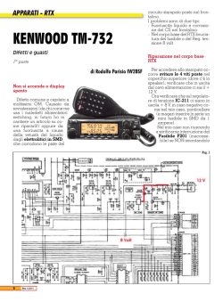
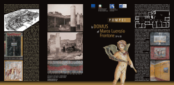
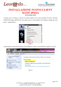
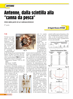
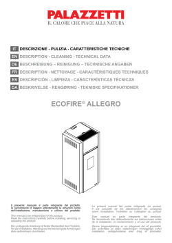
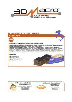
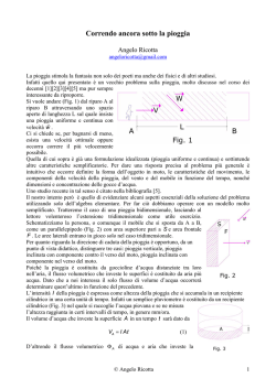
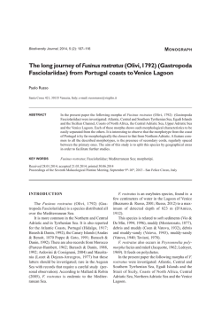
linda b | w e simp l i fy c o n s t r u c t i o n
Rew RA 50
- Unità di ventilazione ad incasso con recupero del calore-
linda b | w e simp l i fy c o n s t r u c t i o n
Descrizione
Le unità di ventilazione ad incasso REW con recupero di calore per singolo locale rappresentano la soluzione
ideale per garantire il ricambio aria e il recupero del calore puntuale in edifici residenziali, uffici, locali pubblici
e commerciali.
Caratteristiche:
• Mandata e ripresa singolo locale
• Scambiatore di calore in ceramica con efficienza fino al 90%
• Ventilatore reversibile EC a basso consumo energertico
• Automazione integrata
• Bassa rumorosità (14-41 dB(A))
• Montaggio e manutenzione semplici e veloci
• Filtri classe G3
• Funzionamento in continuo
• No formazione condensa durante il funzionamento
• Temperature di esercizio [°C] / (°F): da -20°C (-4) fino a +50°C (+122)
Dimensioni e dati tecnici
274 mm
Ø 156 mm
Dimensioni REW RA 50
470 mm
212 mm
Ø 156 mm
254 mm
250 mm
212 mm
Fig. 1. TwinFresh R-50 overall and connecting dimensions
Dati tecnici
Modo
I
II
Alimentazione
Table 5
230V / 50 Hz
Potenza (W)
Portata aria [m3/h](CFM)
1,4
25 (14,7)А
570
50
mm(29,4)
1100
mm
Unit modifications
3,0
inch
Giri/min
Livello sonoro dB(A)
22
B
inch
29
TwinFresh R-50
TwinFresh RА-50
250
9 13/16”
470
18 1/2”
470
18 1/2”
720
28 3/8”
720
28 3/8”
1160
45 11/16”
TwinFresh RА-50 (120V/60Hz)
TwinFresh R-50-М
TwinFresh RА-50-М
TwinFresh RА-50-М (120V/60Hz)
TwinFresh R-50-L
TwinFresh RА-50-L
TwinFresh RА-50-L (120V/60Hz)
IP
45
Design e logica di funzionamento
3
4
2
6
5
6
1
1 - ventilation unit with a decorative grille - 1 item
2 - inner telescopic air duct - 1 item
Unità di ventilazione con
griglia
decorativa
3 - outer
telescopic
air duct - 1 item
Condotto telescopico4 interno
- outer hood (cover, back wall with a pipe) or an outer plastic grille,
Condotto telescopicodepending
esterno on the unit modifications - 1 item
5 - ceramic
heat(dipende
exchangerdall’unità)
- 1 item
Cappa esterna o griglia
in plastica
- 2 items
Scambiatore di calore6 -inFilter
ceramica
123456 - Filtri
Fig. 7. Unit design
L’unità REW dispone di condotti telescopici in plastica (2 e 3), un’unità di ventilazione con griglia decorativa (1)
e una cappa esterna (4).
Il condotto telescopico è regolabile variando la posizione della parte interna (2) all’interno del condotto telescopico esterno (3). I due filtri (6) e lo scambiatore di calore (5) sono installati all’interno del condotto telescopico.
I filtri, disposti su entrambi i lati dello scambiatore di calore, hanno la funzione di purificare l’aria in ingresso ed
evitano l’entrata di polveri e corpi estranei all’interno dello scambiatore.
Il calore scambiato è utilizzato per riscaldare l’aria in ingresso sfruttando l’energia termica recuperata dall’aria
estratta e immettere, perciò, aria calda e filtrata in ambiente.
L’unità di ventilazione con griglia decorativa e la serranda automatica sono installate all’interno della cassa
dell’unità. La cappa esterna si installa dall’esterno per impedire l’ingresso di acqua e corpi estranei nell’unità.
linda b | w e simp l i fy c o n s t r u c t i o n
Installazione e set-up dell’unità
14
14
MOUNTING AND SET-UP
L’unità REW è studiata
l’installazione
parete,
all’interno
di un
appositamente
The unit per
is designed
for installation into aaspecially
designed
through hole inside
a wall.foro
The hole
must be perpendicular to realizzato.
the wall
MOUNTING AND SET-UP
plane.
Il foro dev’essere perpendicolare
al
piano
della
parete.
The mounting guidelines are shown in fig. 9.
The unit is designed for installation into a specially designed through hole inside a wall. The hole must be perpendicular to the wall
plane.
The mounting guidelines are shown in fig. 9.
Fill the gaps
with
a mounting
foam
Riempire
gli spazi
vuoti
con materiale
espanso
INSIDE
INSIDE
INTERNO
ESTERNO
OUTSIDE
OUTSIDE
mm mm
Ø 160 + 10 mm
Fill the gaps with a mounting foam
Fig. 9. Unit mounting
Install the telescopic
in mounting
the hole from outside and fill the gaps between the duct and the wall with a mounting foam. For easy
Fig. duct
9. Unit
Installare il condotto
telescopico
deltheforo
creato
parete e riempire lo spazio vuoto con materiale
mounting
keep the clearancesall’interno
between the duct and
wall within
5-10 mm a
(3/16»-3/8»).
Fix the outer hood according to the wall holes with four 4x35 screws and the dowels 6x35 included into delivery set, fig. 10.
espanso. Per facilitare
l’installazione,
considerare
una
distanza
diandduct
circa
5-10
mm
tra ilfoam.
condotto
e la parete.
Fix
the the
ventilation
unitduct
to the
with from
the screws
3x25
into delivery
theand
dowels
fig. 11.
The mounting
sequence
Install
telescopic
in wall
the hole
outside
andincluded
fill the gaps
betweenset
the
the 5x25,
wall with
a mounting
For easy
for
other unit
modifications
is the
same, fig.
11-12.
mounting
keep
thefori
clearances
between
the
ductparete
and the wallcon
within 5-10
mm (3/16»-3/8»).
Fissare la cappa esterna
ai
applicati
alla
4
viti
4x35
e
grani
6x35
inclusi
nel
kit
consegnato.
Fix the outer hood according to the wall holes with four 4x35 screws and the dowels 6x35 included into delivery set, fig. 10.
Fix the ventilation
the wall with
the screwsnel
3x25 included
into delivery
set and the dowels 5x25, fig. 11. The mounting sequence
Fissare l’unità alla parete
con unit
vitito3x25
incluse
kit e grani
5x25.
for other unit modifications is the same, fig. 11-12.
200 mm
200mm
mm mm
100
200
Ø6
holes
44 fori
Fig. 10. Hole spacing for the outer hood fastening
for TwinFresh R-50.
Fig. 10. Hole spacing for the outer hood fastening
for TwinFresh R-50.
mmmm
200
200200
mm
100mm
mm
100 mm
100
mm
Ø 160 + 10 mm
mm
100
100mm
mm
4 holes
Installazione e set-up dell’unità
Distanza tra i fori per il fissaggio dell’unità
150 mm
75 mm
Ø6
195 mm
97,5 mm
Ø 160 + 10 mm
4 fori
98 mm
196 mm
Distanza tra i fori per il fissaggio dell’unità di controllo e del trasformatore
Ø 68 mm
140 mm
48 mm
CONNECTION AND CONTROL
linda bcontrol
| wunit
e simp
fy cfor
o ncontrolling
s t r u c t i oof
n the TwinFresh R-50 unit. It is available upon order if not included into delivery
The external
KVR isl iused
set of the unit modification.
The control and power unit enables controlling set operation modes and consists of the control unit and transformer unit, fig. 14.
The unit is rated for connection to single-phase 230 V / 50 Hz or 120 V / 60 Hz depending on a transformer type. Separate power supply
must be provided both to the control and power unit and to the ventilator.
The control and transformer unit may be replaced with a control and power unit with the interconnected controller and the transformer
installed in a common junction box.
The control and power unit modification type is selected depending on the power mains voltage and power transformer in accordance
with the Iltable
5.
controllo
è un interruttore a tre pulsanti con scheda elettronica integrata, ed è predisposto per l’installazione
Collegamento e controllo
in
qualunque scatola elettrica. Per facilitare l’installazione e la manutenzione, tutti i collegamenti al controllo vengono effettuati tramite connettori a zoccolo.
del connettore
ha un contrassegno di colore corrispondente
ControlOgni
andparte
power
unit
alla marcatura sulla scheda elettronica per semplificare e rendere più veloce il collegamento elettrico.
Il controllo KVR regola le 4 modalità operative dell’unità (vedi figura sotto).
1 - Modalità ventilazione (mandata/estrazione aria)* a 1 velocità con portata aria 25 m3/h
2 - Modalità ventilazione (mandata/estrazione aria)* a 2 velocità con portata aria 50 m3/h
3 - Modalità recupero a 1 velocità con portata aria 25 m3/h
I ventilatori alternano la propria funzionalità ogni 70 secondi.
4 - Modalità recupero a 2 velocità con portata aria 50 m3/h
I ventilatori alternano la propria funzionalità ogni 70 secondi.
Transformer unit
*la direzione del flusso d’aria dipende dalla posizione del jumper JMP1 sulla scheda elettronica
KVR
control unit
Modalità
estrazione
Velocità
2
ON
KVR-T control and power unit
82 mm
Vano
trasformatore
153 mm
60 mm
Fig. 14. KVR and KVR-T control unit (overall view)
Modalità
inversione
OFF
Velocità
1
Schema generale di collegamento
Schema generale di collegamento dell’unità al controllo KVR.
Due canali permettono di collegare l’unità al controllo KVR. In modalità di recupero, le unità collegate al canale
“A” funzionano in modalità di mandata e quelle collegate al canale “B” in modalità di ripresa.
Questa modalità di funzionamente può essere anche impostata settando il jumper sulla scheda elettronica di
tutte le unità in posizione di “flusso in uscita”.
In modalità di ventilazione, le unità funzionano in modalità estrazione settando il jumper JMP1sulla scheda elettronica dell’unità in posizione di “flusso in uscita”, o in modalità mandata settando il jumper JMP1 sulla scheda
elettronica dell’unità in posizione di “flusso di entrata”.
Per facilitare l’installazione viene utilizzato un cavo a 5 fili di diversi colori. I conduttori hanno sezione minima di
0,25 mm2. Il tipo e la potenza del trasformatore di riduzione T1 sono selezionati considerando che per il funzionamente di una singola unità è necessaria una tensione in corrente alternata di 12 V e l’assorbimento dell’unità
è pari a 3 W.
KVRKVR
controller
~120 V
or
~230 V
~120 V
or
~230 V
~120 V
or
~230 V
T1 (12 W)
Channel
REWA:1. TwinFresh R-50
Channel
~120 V
or
~230 V
Fig. 17. General wiring diagram for connection of up to 4 TwinFresh R-50 units to KVR controller
To connect from 2 to 4 TwinFresh R-50 units, follow the wiring diagram in fig. 17. This wiring example shows connection through 12 W power tra
Power supply 230 V / 50 Hz or 120 V / 60 Hz must be provided both to KVR (KVR-T) control unit and to each fan (socket connectors 31-21 for each
The inputs at the controller socket connectors are marked 21 to 25.
The outputs at the controller socket connectors are marked 11 to 15.
The socket connectors on the delivered connecting cable are marked 1 to 5 and are designed for connection to the controller socket connectors
REW
Channel A:1. Twin
50
~120 V
or
~230 V
~120 V
or
~230 V
REW resh R-50
Channel A:N. TwinF
REW
Channel B:N. TwinFresh
R-50
To connect from 2 to 4 TwinFresh R-50 units, follow the wiring diagram in fig. 17. This wiring example shows connection through 12 W power transformer or 12 W control and power unit.
Power supply 230 V / 50 Hz or 120 V / 60 Hz must be provided both to KVR (KVR-T) control unit and to each fan (socket connectors 31-21 for each case).
The inputs at the controller socket connectors are marked 21 to 25.
The outputs at the controller socket connectors are marked 11 to 15.
The socket connectors on the delivered connecting cable are marked 1 to 5 and are designed for connection to the controller socket connectors , 11-15 for outputs and 21-25 for inputs.
Fig. 17. General wiring diagram for connection of up to 4 TwinFresh R-50 units to KVR controller
T1 (12 W)
~120 V
or
~230 V
~120 V
or
~230 V
KVR controller
KVR
Channel B:1. Twin
REW
~120 V
or
~230 V
~120 V
or
~230 V
linda b | w e simp l i fy c o n s t r u c t i o n
Per il20
collegamento in serie (fino a 4 unità), seguire lo schema di collegamento sotto.
LINDAB S.r.l
Sede
Via Pisa 5-7 - 10088 Volpiano (TO)
Tel. 011.99.520.99 - Fax 011.99.524.99
E-mail: [email protected]
Filiale
Via Cagliari SNC - 20060 Trezzano Rosa (MI)
Tel. 02.95.34.50.98 - Fax 02.95.34.92.76
E-mail: [email protected]
Scarica gratis un’applicazione per leggere il codice QR dal tuo smartphone
e potrai accedere direttamente al nostro sito web. Potrai scaricare le schede
tecniche dei nostri prodotti e trovare informazioni e news aziendali
www.lindab.it
© Copyright 2026 Paperzz