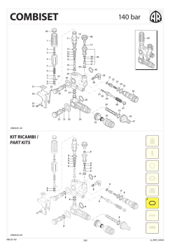
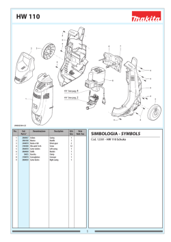
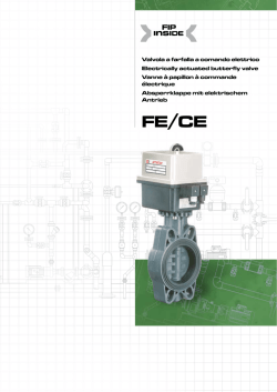
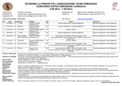
I
E
D
F
GARANZIA
I nostri prodotti sono garantiti per mesi
12 dalla consegna. La Ditta si assume la
responsabilità per tutti quei particolari
che presentassero difetti di materiale o di
lavorazione. Non è riconosciuta la garanzia
per cattiva manutenzione, anormale
impiego e per quelle parti non costruite
dalla Ditta. Le riparazioni dovranno essere
effettuate presso la fabbrica o da personale
autorizzato. Nello stesso istante in cui i
prodotti saranno manomessi da terzi, ogni
garanzia sarà ritenuta scaduta. Per ogni
verifica i prodotti dovranno essere inviati in
Porto Franco. Nel caso di effettiva necessità
di sostituzione di particolari sarà addebitato
il solo costo della mano d’opera. Per il vostro
fabbisogno di ricambi chiedete sempre
ricambi originali. In caso diverso non sarà
riconosciuta alcuna garanzia.
Numero per ordini telefonici:
(+39) 059.414.411
Numero per ordini con fax:
(+39) 059.253.505
GARANTIA
Nuestros productos están garantizados
por 12 meses desde la fecha de la entrega.
Ninguna garantía será reconocida por malo
entretenimiento o por uso incorrecto de
los productos. Pidan siempre repuestos
originales. En caso contrario no se
reconocerá ninguna garantía.
GARANTIE
Die Firma gewährt eine Garantie von 12
Monaten, gerechnet vom Lieferdatum.
Zweckfremder Einsatz und/oder nachlässige
Wartung schließen jede Garantie aus. Im
Bedarfsfall immer Original-Ersatzteile von
der Firma anfordern. Anderenfalls kann
keine Garantie gewährt werden.
GARANTIE
Nos produits sont garantis pour 12 mois
à partir de la date de livraison. Aucune
garantie ne sera reconnue, suite au
mauvais entretien ou emploi anormal des
produits. Pour tous vos besoins de pièces de
rechange, demandez toujours les rechanges
originaux. Au contraire, aucune garantie ne
sera reconnue.
Our products are guaranteed for a period
of 12 months after the date of delivery.
Warranty will not be acknowledged if the
products are not used according to the
manufacturer’s instruction or are badly
maintained. Always ask for original Spareparts, otherwise warranty will not be
acknowledged.
GB WARRANTY
Lubrificare con GRASSO Molykote G807
Lubricate with Molykote G807 GREASE
Avvitare con Loctite 5331 (Bianca)
Screw down with Loctite 5331 (White)
Lubrificare con GRASSO Molykote PG54
Lubricate with Molykote PG54 GREASE
Lubrificare con GRASSO Molykote 1000
Lubricate with Molykote 1000 GREASE
Lubrificare con GRASSO P40
Lubricate with P40 GREASE
Coppia serraggio Tolleranza +0/-10% Nm
Tightening torque tolerance +0/-10% Nm
Lubrificare con OLIO MOTORE
Lubricate with ENGINE OIL
Lubrificare con GRASSO MINERALE
Lubricate with MINERAL GREASE
Montare con PRESSA
Assemble with PRESS
Montare a caldo con RISCALDATORE
Assemble hot with HEATER
Avvitare con Loxeal 83-21 Frenafiletti FORTE (Verde)
Screw down with Loxeal 83-21 STRONG (Green)
thread sealer
Avvitare con Loxeal 55-14 Frenafiletti MEDIO (Rosso)
Screw down with Loxeal 55-14 MEDIUM (Red) thread
sealer
Avvitare con Loxeal 24-18 Frenafiletti DEBOLE (Porpora)
Screw down with Loxeal 24-18 WEAK
(Purple) thread sealer
Incollare con Loctite 454
Glue with Loctite 454
Spruzzare un velo di Molykote D-321R Spray
Spray on a light coat of Molykote D-321R
Sigillare con Arexons PIK
Seal with Arexons PIK
Sigillare con Arexons Mastice
Seal with Arexons Filler
Sigillare con Arexons MOTORSIL D
Seal with Arexons MOTORSIL D
Incollare con Biadesivo acrilico VHB-3M 4945
Glue with VHB-3M 4945 acrylic biadhesive
Avvitare con Loctite 2701 Frenafiletti FORTE (Verde)
Screw down with Loxeal 83-21 STRONG (Green)
thread sealer
Prescrizioni per Montaggio
Prescription for Assembly
Member of
AT E N Ç Ã O :
ATTENZIONE:
AT TENTION:
ACHTUNG:
AT E N C I O N :
AT TENTION:
IDROMINUS
160
l/min
42,3
gpm (US)
OUTPUT
DEBIT
LEISTUNG
CAUDAL
PORTATA
20
bar
290
psi
PRESSURE
PRESSION
DRUCK
PRESION
PRESSIONE
4-5-6
N. VALVES
N. ROBINETS
N. VENTILEN
N. ROBINETS
N. RUBINETTI
This manual must be read before beginning installation of the unit.
Ce livret doit être lu avant d’installer et d’employer le produit.
Das vorliegende Handbuch ist vor der Installation und dem Gebrauch des Produkts aufmerksam zu lesen.
Este manual debe ser leído antes de proceder a la instalación Y uso del producto.
Este manual deve ser lido antes de proceder à la instalação e ao uso do producto.
Il presente libretto va letto prima di procedere all’installazione ed uso del prodotto.
CONTROL UNITS
GROUPES DE COMMANDE
BEDIENUNGSARMATUREN
GRUPOS DE MANDO
GRUPPI COMANDO
3÷3,2
kg
WEIGHT
POIDS
GEWICHT
PESO
PESO
TECHNICAL DATA / DONNEES TECHNIQUES / TECHNISCHE ANGABEN
CARACTERISTICAS TÉCNICAS / CARACTERÍSTICAS TÉCNICAS / CARATTERISTICHE TECNICHE
- Remote control distributors for low pressure pumps - Grupos de mando separados para bombas baja presion
- Groupes de commande separes pour pompes
- Gruppi comando separati per pompe a bassa pressione
basse pression
- Separate Bedienungsarmaturen für
IDROMINUS
Niederdruckpumpen
Via M.L.King,3 - 41122 Modena (Italy)
Tel. (+39) 059.414.411 - Telefax (+39) 059.253.505
E - Mail Italia: [email protected]
E - Mail export: [email protected]
ANNOVI REVERBERI S.p.A.
cod. 99158-BT
Characteristics and descriptions are not binding. -Données descriptions et illustrations n’ engagement pas le constructeur. - Angaben, Beschreibungen, und illustrationen sind nicht
verbindlich. - Noticias y ilustraciones no son empeñativas. - Os dados, descrições e ilustrações são fornecidos a título informativo e não comprometem o fabricante. - Dati, descrizioni ed
illustrazioni sono forniti a titolo indicativo e non impegativo.
IDROMINUS
30
34
35
36
110
33
89
37
31
83
47
50
46
51
52B
45
19
39
114
43
42
111
110
54
112
24
41
48
113
53
114
2-1
2-2
34
UN970188-DD
UN970187-DD
63
35
38 87 88 70
57
50
44
105
58
41
55
125 84
51
50
102
52A
48 126 71 127 61 24
51
44
59
71
116
120
50
35
34
122 123 124
56
101
117
34
98
121
128
119
13
98
48
42
115
97
96
129
49
70 118
100
50
99
51
2-3
2-4
55
52
SL000112-GY
UN970189-DD
90
58
14 15
91
16 11
21
40 17 26
1
25
2
21
44
3
73
60
58
62
58
17
27
90
44
44
64
12
24
22 23
13
10
18
19
20
44
5
58
62
24
44
24
UN970191-DD
60
24
2-5
IDROMINUS
Pos.
Cod.
1
2
3
5
10
11
12
13
14
15
16
17
18
19
21
22
24
25
26
27
30
31
33
34
35
36
37
38
39
40
41
42
43
44
45
46
47
48
49
50
51
52
53
54
55
56
57
58
59
60
61
62
63
64
70
71
73
83
84
87
88
89
90
91
96
97
98
395430
395590
395420
395410
395400
395470
394690
390330
390341
393790
395480
390313
395450
180101
392600
392604
640070
392580
392870
392590
392620
390291
395490
1080190
393300
395560
394790
391560
390440
550331
394780
395570
395541
395551
395460
394830
392330
394700
395530
394800
550450
391240
660170
394810
550350
550242
550210
394840
550340
550370
395000
395520
390060
395020
395440
770260
395500
395510
395580
392120
880581
390080
392551
395390
880830
480480
1660580
395760
395770
396100
395081
395071
20
23
Descrizione
Reg. scarico pressione
OR ø 8x2,5
Deviatore
Forcella
Corpo rubinetto 2 vie
Valvola chiusura
Leva rubinetto rossa
Spina elastica
OR ø 5x2
Rosetta øi 6,4
Molla
Rosetta øi 9
Asta valvola completa
OR ø 17,5x2
Niples sede 20x1,5
Tappo
OR ø 13,95x2,62
Forcella
Portagomma ø 10
Portagomma ø 12
Portagomma ø 20
OR ø 28,25x2,62
Rosetta øi 6
OR ø 2,90x1,78
Spina elastica
Distanziale
Manopola regolazione
Dado M 6 H 8
Dado M 6
Rosetta øi 6,5
Corpo superiore
Centraggio
Asta valvola
Valvola volumetrica
Molla
Prigioniero M 6x34
Prigioniero M 6x30
Corpo valvola reg.
Forcella
Attacco manometro
Girello 3/4” G
Manometro ø 63
OR ø 31,42x2,62
Flangia entrata
OR ø 23,81x2,62
Girello 1” G
Tubetto ø 25
Flangia chiusura
Niples 1”G(M)-1”G(M)
Curva ø 25
Niples collettore
Collettore corpo reg.
OR ø 20,63x2,62
Coll. corpo principale
Tappo chiusura lat.
OR ø 23,52x1,78
Collettore laterale 2vie
Collettore centrale
Biforcella
Spina elastica
Tappo 1/4” G
OR ø 11,91x2,62
Rosetta øi 6
Dado M6
OR ø 15,54x2,62
OR ø 4,48x1,78
OR ø 40,95x2,62
Collettore laterale 3vie
Corpo rubinetto 3 vie
Coperchio filtro OR ø 47,30x2,62
Guarnizione filtro
Description
Q.ty
Press.discharge adjust. 4
O-Ring
4
Body
4
Fork
4
2-way valve body
2
Valve
4
Red valve lever
4
Pin
5
O-Ring
4
Washer
4
Spring
4
Washer
8
Complete valve rod
4
O-Ring
5
Threaded adapter
4
Plug
-
O-Ring
8
Fork
4
Hose tail
4
Hose tail
4
Hose tail
4
O-Ring
7
Washer
4
O-Ring
4
Pin
4
Spacer
1
Adjustment knob
1
Nut
1
Nut
16
Washer
12
Upper body
1
Spigot
1
Complete valve rod
1
Volumetric valve
1
Spring
4
Stud
8
Stud
8
Regulating valve body
1
Fork
7
Pressure gauge attach. 1
Ring nut
1
Pressure gauge
1
O-Ring
3
Flange
1
O-Ring
5
Ring nut
3
Hose tail
3
Flange cover
1
Threaded adapter
1
Elbow
1
Manifold nipples
1
Body manifold
1
O-Ring
3
Body manifold
1
Plug
2
O-Ring
1
2-way lateral manifold 2
Central manifold
1
Fork
2
Pin
2
Plug
2
O-Ring
4
Washer
1
Nut
1
O-Ring
1
O-Ring
1
O-Ring
1
3-way lateral manifold 2
3-way valve body
2
Filter cover
1
O-Ring
1
Filter gasket
2
Note
Optional
Pos.
Cod.
99
100
101
102
105
110
111
112
113
114
115
116
117
118
119
120
121
122
123
124
125
126
128
129
396110
396130
395030
394820
850730
1452
1450
1351
1553
1451
1660560
1660140
1660020
480561
1660010
1660230
1660541
1660050
1660090
1660080
393790
1660060
1660100
1660110
1660120
1660551
396590
127
0-24bar
Descrizione
Filtro interno
Rete esterna
Scatola filtro
Staffa
Forcella Gruppo rubinetto 2vie
Valvola reg. completa
Corpo distributore+R
Gruppo filtro compl.
Gruppo rubinetto 3vie
Leva comando
Rosetta øi 10,5
Asta valvola
OR ø 6,85x1,78
Corpo valvola reg.
OR ø 13x2
Molla
Valvola aliment.barra
Molla
Guida comando risuc.
Rosetta øi 6,4
Flangia risucchio
Sede risuc. ø 7 Rosso
Sede risuc. ø 9 Arancio
Sede risuc. ø 10,5 Blu
OR ø 7x2 Tappo 3/8” G+guarn.
•
Description
Internal filter
External grid
Filter box
Braket
Fork
2-way valve
Compl.reg.valve
Distributor body+R
Complete filter
3-way valve
Control lever
Washer
Complete valve rod
O-Ring
Main valve
O-Ring
Spring
Feed rod valve
Spring
Guide
Washer
Flange
Red seat
Orange seat
Blue seat
O-Ring
Plug & gasket
Per/For: AR 70 bp
Per/For: AR 115-135 bp - AR 125-145 bp
Per/For: AR 160 bp
•
Viton
1
1
1
1
1
2
1
1
1
2
1
1
1
2
1
1
1
1
1
1
1
1
1
1
1
1
1
Uscita/Outlet ø 12
Uscita/Outlet ø 12
Vedi/See
Vedi/See
Vedi/See
Viton
•
Per/For: AR 60 bp
Per/For: AR 100 bp - AR 120 bp
Per/For: AR 150 bp
KIT 2335
OR
O-Rings
20
Note
Nota: Le quanità espresse sono riferite alla versione a 4 rubinetti
Note: The quantities refer to the 4 valves version
KIT 2334
Q.ty
Pos.
Q.ty
2
14
19
21
24
26
48
50
58
61
73
4
4
5
8
7
4
3
5
3
1
4
Pronto intervento
Mantenance repair
Pos.
Q.ty
87
88
89
97
118
120
128
1
1
1
1
2
1
1
Pos.
Q.ty
2
11
12
14
18
22
24
39
51
55
58
4
2
2
4
4
2
7
1
1
1
3
Pos.
Q.ty
60
61
73
87
98
115
118
122
124
128
1
1
4
1
2
1
2
1
1
1
DISTRIBUIDOR IDROMINUS
DESCRIZIONE E MODO D’USO
Il distributore IDROMINUS serve per la regolazione della pressione di lavoro e al mantenimento costante della quantità di prodotto per unità di
superficie. Impiegato negli impianti da diserbo e concimazione liquida.
COLLEGAMENTO TUBI
Al raccordo 55 va collegato il tubo che arriva dalla mandata pompa. Ai
raccordi 52A e 52B vanno collegate le tubazioni di ritorno al serbatoio.
La tubazione 52A deve solo entrare nel serbatoio, la 52B deve continuare
fino al fondo del serbatoio distante dalla pompa. Ai raccordi 23 vanno collegati: tubi alimentazione barra, agitatore idraulico ed eiettore.
REGOLAZIONE DELLA PRESSIONE DI LAVORO
A macchina ferma accertarsi che:
1.La leva comando 115 sia girata verso il basso pos. 0 (tutto scarico).
2.La manopola 31 di regolazione sia svitata fino inizio filetto corpo 36.
3.Le leve rubinetti 12 siano girate verso l’ alto aperto alimentazione barra.
4.Tutte le manopole 1 avvitate a fondo e svitate di 2 giri e mezzo (Pos.
I).
PROVA CON ACQUA
1.Avviare la pompa a macchina ferma con presa di forza a giri 550 max o,
ai giri corrispondenti alla velocità in Km/h scelti per il trattamento.
2.Alzare la leva 115 e avvitare la manopola fino ad ottenere la pressione
di lavoro richiesta visibile sul manometro 47.
3.Chiudere una alimentazione barra abbassando la leva del rubinetto 12.
In questo momento vi potrà essere una diminuzione della pressione
che, sarà riportata al valore scelto avvitando gradualmente la manopola 1.
4.Ripetere l’ operazione 3 per tutte le alimentazioni barra e agitatore.
N.B. Se una uscita del rubinetto non è utilizzata abbassare la leva 12 e la
manopola 1 dello stesso dovrà rimanere chiusa (avvitare).
5.Aprire tutti i rubinetti regolati alzando le leve 12.
A questo punto l’ IDROMINUS è pronto per essere impiegato. Ad ogni singola chiusura e a variazioni di giri programmati +15% -15% nell’ ambito
della stessa marcia scelta del trattore, non provocherà cambiamenti nella
quantità di prodotto per unità di superficie distribuito (Volume per ettaro
costante). Volendo arrestare l’ alimentazione barra abbassare la leva 115
pressione zero/tutto scarico. Per ritrovarsi nelle condizioni di lavoro precedenti girare la leva 115 verso l’alto.
USO DELL’ EIETTORE
1.Manopola di regolazione 31 svitata fine-filetto corpo 36.
2.Chiudere i rubinetti alimentazione barra leve in basso.
3.Aprire il rubinetto sul quale è stato collegato l’ eiettore 12 in alto.
4.Alzare la leva principale 115.
5.Regolare la pressione del distributore al max consentito, visibile sul
manometro 47 avvitando la manopola 31 e procedere al riempimento
del serbatoio.
Ricordare che ad ogni sostituzione dei getti barra e all’ impiego dell’ eiettore, è necessario rivalutare le istruzioni “REGOLAZIONE DELLA PRESSIONE
DI LAVORO”.
IMPORTANTE
Ad ogni fine trattamento è buona norma procedere ad una pulizia dell’
impianto tramite circolazione di acqua pulita.
DISTRIBUTORE IDROMINUS
I
REGELARMATUR IDROMINUS
DESCRIPCIÓN Y FORMA DE EMPLEO
El distribuidor IDROMINUS, sta preparado para la regulacion de la presiòn
de trabajo y el mantenimiento costante de la cantidàd de producto aplicado, por unidad de superficie; en la aplicaciòn de hervicidas y abonos
liquidos.
CONEXIÓN TUBOS
La conneccion 55 va unido al tubo que llega del colector de la bomba. Los
recores 52A y 52B, van unidos a la tuberia de retorno al depòsito.
El tubo 52A debe entrar justo en el depòsito, el 52B debe continuar hasta
el fondo del depòsito, pero distanciado de la aspiraciòn de la bomba. Los
racores 23 van unidos a: los tubos de alimentaciòn de la barra, al agitador
hidràulico y al inyector.
REGOLACIòN DE LA PRESSIONE DE TRABAJO
Con la màquina parada comprobar que:
1.La palanca de mando 115, esté orientada hacia abajo , en posiciòn 0
(descarga total).
2.La maneta 31 de regolacion debe ser desenroscada hasta el inicio de la
rosca del cuerpo 36.
3.La palanca de los grifos 12 seran giradas verso hacia arriba, albierta la
alimentaciòn de la barra.
4.Todas las manetas 1 roscadas hasta el fondo, y desenroscar dos vueltas
y media (Pos. I).
PRUEBA CON AGUA
1.Poner en marcha la barra con la màquina parada, con la toma de fuerza
a 550 r.p.m. màximo, o a las vueltas correspondientes a la velocidad en
Km/h ascogida para el tratamiento.
2.Alzar la palanca 115 y roscar la mananeta 31 hasta obtener la presiòn
de trabajo deserada, visible en el manòmetro 47.
3.Cerrar una de las alimentaciones de la barra, bajando la palanca del
grifo 12. En este momento producirà una disminuciòn de la presiòn,
que se recuperarà al valor deserado roscando gradualmente la maneta
1.
4.Ripetir la operaciòn 3 en todas las alimentaciones de la barra y en el
agitador.
N.B. Si una no es utilizada, bajare la palanca 12 y la maneta 1 de la misma
deberà permanecer cerrada (roscada).
5.Abrir todos los grifos reglados, alzando la maneta 12.
En este momento el IDROMINUS estarà en condiciones de ser empleado.
Aun con el cierre de alguno de lo grifos y con variaciòn de la revoluciones
programadas en +15% -15% a la misma marcha seleccionada del tractor,
no se produciràn cambios en la cantidàd de producto por unidad de superficie a tratar (Volumen per ettaro costante).
En caso de desear detener la alimentaciòn de la barra, bajar la palanca
115 presiòn cero: descarga total. Para volver a las condiciones de trabaio
precedente, alzar la palanca 115.
USO DEL INYECTOR
1.Maneta de regulacion 31 denroscada hasta el principio de los rosca del
cuerpo 36.
2.Cerrar los grifos de alimentaciòn de la barra, palanca 12 abajo.
3.Abrir el grifo al cual ha sido empalmado en inyector, palanca 12 arriba.
4.Alzar la palanca principal 115.
5.Regular la presiòn del distribuidor al màximo posible, visible en el
manometro 47, roscando la maneta 31 y proceder al llenadoo del depòsito.
Recordar que a cada sustituciòn de las boquillas de la barra y al empleo
del inyector es necesario aplicar de nuevo las instrucciones “REGULACIòN
DE LA PRESIòN DE TRABAJO”.
IMPORTANTE
A cada final de tratamiento es una norma muy recomendable proceder a
una limpieza de la instalaciòn, haciendo circular por ella agua limipa.
ISTRUZIONI PER LA SICUREZZA
È necessario conservare con cura il presente manuale, leggere e
rispettare le seguenti istruzioni per la sicurezza:
• Non utilizzare il prodotto con fluidi infiammabili o aventi caratteristiche non compatibili con il corretto funzionamento del
prodotto stesso.
• L’istallazione del prodotto deve essere effettuata da personale
qualificato.
E
DISTRIBUTEUR IDROMINUS
BESCHREIBUNG UND GEBRAUCH
Die Regelarmatur IDROMINUS dient zur Regelung des Arbeitsdrucks und
zur Konstanthaltung der Ausbringmengen (1/ha) von Geräten zur Ausbringung von Sprizmitteln und Flüssigdüngern.
ANSCHLUSS DER SCHLÄUCHE
Am Anschluß 55 wird der Druckschlauch von der Pumpe angeschlossen.
Von den Anschlüssen 52A und 52B werden Rücklaufschläuche zurück in
den Behälter geführt. Der Schlauch von Anschluß 52A muß frei in den
Behälter geführt werden. Vom Anschluß 52B kann eine Leitung an den
Behälterboden-in ausreichendem Abstand von der Auslauföffnung - geführt werden. Die Anschlüsse 23 dienen für: Speisung des Spritzgestänges, hydraulische Rühreinrichtung und Füllinjektor.
REGELUNG DES ARBEITSDRUCKS
Bei abgestelltem Gerät gent man wie folgt vor:
1.Der Hebel 115 wird auf die niedrige Position 0 gestellt.
2.Der Drehgriff 31 des Druckreglers wird nach links gedreht bis zum
Gewindeanfang am Teil 36.
3.Die Ventilhebel 12 zur Speisung des Spritzgestänges etc; werden nach
oben in geöffnete Position gestellt.
4.Alle Einstellschrauben 1 werden nach rechts bis zum Anschlag zugedreht und dann 2 1/2 Umdrehungen nach links geöffnet (Pos. I).
PROBE MIT REINEM WASSER
1.Bei stehendem Schlepper Pumpe mit der bei der Arbeitsgeschwindigkeit benötigten Drehzahl (höchstens 550 U/min) anlaufen lassen.
2.Hebel 115 nach hoch stellen und Drehgriff 31 nach rechts eindrehen bis
der gewünschte Arbeitsdruck am Manometer 47 erreicht ist.
3.Eine Abgangsleitung zum Spritzgestänge schließen indem man einen.
Ventilhebel 12 nach unten stellt. Sinkt oder steigt der eingestellte Arbeitsdruck, so muß die Einstellschraube 1 so weit nach rechts oder nach
links gedreht werden, bis der ursprünglich eingestellte Druck wieder
erreicht ist.
4.Wiederholen Sie den unter 3. Beschriebenen Vorgang nacheinander
an allen Ventilhebeln 12. Wenn ein Abgangsventil nicht benutzt wird,
stellen Sie den entsprechenden Ventihebel 12 nach unten und drehen
die Einstellschraube 1 ganz nach rechts ein.
5.Öffnen Sie alle eingestellten Ventile indem Sie die Ventilhebel 12 nach
oben stellen.
Nun ist die “IDROMINUS” betribsfertig. Bei jeder Teilbreitenschaltung und
bei Änderungen der Fahrgeschwindigkeit im Bereich von +15% -15%
vom vorgesehenen Wert ändert sich die Ausbringemenge je Flächeneinheit (1/ha) nicht (Automatikfunktion). Zum gleichzeitigen Abstellen
aller Ventile Hebel 115 niedriger stellen. (Der Druck sinkt dann auf 0, die
gesamte Pumpenfördermenge geht in den Rücklauf). Zum Betrib mit den
eingestellten Werten wird der Hebel 115 wieder nach hoch gestellt.
INJEKTORBETRIEB
1.Drehgriff des Druckreglers 31 nack links drehen bis zum Gewindeanfang am Teil 36.
2.Alle Ventilhebel 12 zur Speisung des Spritzgestänges nach unten stellen (schließen).
3)Den Ventilhebel 12 zur Speisung des Injektors nach oben stellen (öffnen).
4.Den Haupthebel 115 nach unten stellen.
5.Den Drehgriff des Druckreglers 31 nach rechts drehen bis zum Erreichen
des höchstzulässigen Betriebsdrucks (rote markierung am Manometer
47) und Injektor laufen lassen bis der Behälter gefüllt ist.
Denken Sie daran, daß nach jedem Düsenwechsel und nach jeder Benutzung des Injektors die Anweisungen zur “Regelung des Arbeitsdrucks”
entsprechend befolgt werden müssen.
WICHTIG
Nach jeder Anwendung sollte das gesamte Gerät mit reinem Wasser durchgespült werden.
INSTRUCCIONES PARA LA SEGURIDAD
Es necesario conservar con cuidado el presente manual, leer y
respetar las siguientes instrucciones para la seguridad:
• No utilizar el producto con fluidos inflamables o que tengan
características no compatibles con el correcto funcionamiento
del producto.
• La instalación del producto debe ser efectuada por personal
especializado.
D
IDROMINUS CONTROL UNIT
DESCRIPTION ET MODE D’EMPLOI
Le distributeur IDROMINUS assure le réglage de la pression de travail
et maintient constante la quantité de produit utilisée dans les installations de distribution de désherbants et d’ engrais liquides.
RACCORDEMENT DES TUYAUX
Brancher le tuyau de refoulement de la pompe au raccord. Brancher
aux raccords 52A e 52B les tuyaux de retour cuve. Le tuyau du 52A
doit seulement rentrer dans la cuve, tandis que le 52B doit être en
contact avec le fond de la cuve, loin de l’ aspiration de la pompe.
Brancher aux raccords 23 les tuyaux d’ alimentation de la rampe,de
l’agitateur hydraulique et de l’ éyecteur.
REGLAGE DE LA PRESSION DE TRAVAIL
Avec l’ appareil en statique vérifier que:
1.Le levier 115 est tourné vers le bas, position 0 (by-pass).
2.La poignée 31 est dévissée jusqu’ au debut du filet du corps 36.
3.Les leviers 12 sont tournés vers le haut, alimentation rampe.
4.Toutes les pointeaux 1 vissés au fond puis devissé de deux tours et
demi (Pos. I).
ESSAI EN EAU
1.Mettre en marche la pompe, appareil en statique, prise de force au
régime correspondant a la vitesse choisie pour le traitement, avec
un maxi de 550 tr/mn.
2.Soulever le levier 115 et visser la poignée 31 pour obtenir la pression de travail nécessaire qui se lit sur le manometre 47.
3.Fermer un robinet d’ alimentation de la rampe en baissant le levier
du robinet 12. Ace moment-là, il pourra se produire une baisse de
pression. Visser, le poiteau 1 jusqu’ a retrouver sur le manométre la
valeur de la pression initialment choisie.
4.Répéter l’ opération 3 pour tous les robinets qui alimentent la rampe.
NB: si une sortie n’ est pas utilisèe, baisser le levier 12 correspondant
et visser complétement le poiteau 1.
5.Ouvrir tous les robinets d’ alimentation de la rampe en levant les
leviers 12.
A ce stade, l’ IDROMINUS est prêt a i’ emploi. En cas de fermeture d’
une section de la rampe ou de variation de la vitesse de +15% -15%
sur un rapport de boite de vitesse invarié, la dose de liquide distribuée a l’ hectare ne sera pas modifiée. Pour arrêter l’ alimentation
de la rampe, baisser le levier 115 (pression à 0/tout decharge). Pour
se retrouver dans les conditions précédentes, il suffira de soulever le
levier 115.
EMPLOI DE L’ EJECTEUR
1.Poignée de réglage 31 dévissé jusqu’ à la fin du filet du corps 36.
2.Fermer les robinets d’ alimentation rampe, leviers en bas.
3.Ouvrir le robinet sur lequel est branché l’ éjecteur levier 12 vers le
haut.
4.Soulever le levier principal 115.
5.Régler la pression du distributeur au maximum possible, visible
sur le manométre 47 en vissant la poignée 31 et procéder au remplissage de la cuve.
Il est nécessaire, aprés tout changement de buses ou utilisation de
l’ éjecteur de recommencer le “REGLAGE DE LA PRESSION DE TRAVAIL”.
IMPORTANT
A chaque fin de traitement, il sera nécessaire de procéder à un nettoyage par circulation d’ eau pure.
SICHERHEITSANLEITUNGEN
Vorliegendes Handbuch sorgfältig aufbewahren und folgende
Sicherheitsanleitungen aufmerksam lesen und beachten:
• Produkt nicht mit entzündbaren oder sonstigen Flüssigkeiten
verwenden, deren Eigenschaften mit einem einwandfreien
Betrieb des Produkts nicht vereinbar sind.
• Die Produktinstallation ist von qualifiziertem Fachpersonal vorzunehmen.
F
DESCRIPTION AND USE
The IDROMINUS regulates the pressure and maintains constant output of products used for spraying and liquid fertilizing.
HOSE CONNECTIONS
The pressure hose from the pump is connected to hose-tail 55. The
tank return hoses are connected to hose tails 52A and 52B.
The hose from 52A must be placed just inside the tank, while the
hose from 52B must go to the bottom of the tank, far from pump suction. Boom feed hose, hydraulic agitator and ejector are connected
to hose-tails 23.
WORKING PRESSURE REGULATOR
With unit shut-off check that:
1.Control level 115 is pointing downwards in 0 position (all bypass).
2.Regulating knob 31 is completely unscrewed right up to beginning
of threads on body 36.
3.Valve levers 12 are turned upwards-boom feed open.
4.All knobs 1 screwed as far as they will go, then unscrewed two and
a half turns (Pos. I).
TEST WITH WATER
1.PUMP START UP (with machine standing still) with 550 RPM P.T.O.
or with revs corresponding to speed selected for spraying.
2.Raise lever 115 and screw knob until you reach required working
pressure-see pressure gauge 47.
3.Close one boom feed by lowering-ok valve lever 12. At this stage
the pressure may decrease, it is brought back to required level by
screwing knob 1.
4.Repeat operation 3 for all boom feeds and agitator.
NB: If one outlet isn’ t used, lower 12 and keep valve knob 1 closed
(screw).
5.Open all regulated valves by raising levers 12.
At this stage the IDROMINUS is ready for use. If any single valve is
shut-off or if tractor revs by +15% -15% in the same gear, there
will be no change in the quantity of product distributed (constant
volume per hectare).
To stop boom feed lower lever 115 Zero pressure/All by-pass. To start
working again as before turn lever 115 upwards.
EJECTOR
1.Regulating knob 31 unscrewed right up the end of threads on
body 36.
2.Close boom feed valves by lowering levers 12.
3.Open valve where ejector has been connected-Lever 12 pointing
upwards.
4.Raise main lever 115.
5.Regulate pressure of control unit to max. allowed (see pressure
gauge 47), by screwing knob 31 and proceed with filling tank.
Remember that each time nozzles are changed or an ejector is used,
you must reset following the instructions for working pressure regulation.
IMPORTANT
After use it’s a good idea to clean control unit by running clean water
through it.
INSTRUCTIONS DE SECURITE
Conserver ce manuel avec le plus grand soin. Lire et respecter les
instructions de sécurité ci-dessous:
• Ne pas utiliser le produit avec des fluides inflammables ou ayant
des caractéristiques incompatibles avec le fonctionnement correct du produit lui-même.
• L’installation du produit doit être effectuée par un personnel
qualifié.
GB
SAFETY INSTRUCTIONS
This manual must be stored carefully. Read and follow the following safety instructions:
• Do not use the unit with flammable liquids, or liquids with characteristics not compatible with the correct functioning of the
unit.
• The installation of the unit must be carried out by qualified
staff.
© Copyright 2026 Paperzz