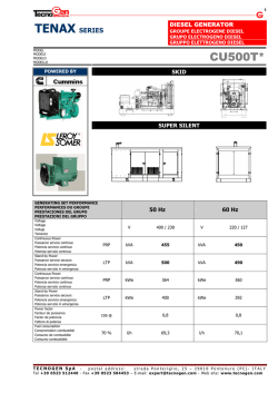
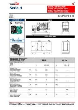
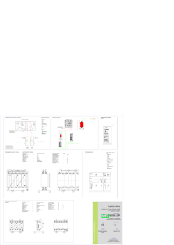
1 DIESEL GENERATOR TENAX SERIES GROUPE ELECTROGENE DIESEL GRUPO ELECTROGENO DIESEL GRUPPO ELETTROGENO DIESEL MODEL MODÈLE MODELO MODELLO CU 1400 T POWERED BY SKID SUPER SILENT GENERATING SET PERFORMANCE PERFORMANCES DU GROUPE PRESTACIONES DEL GRUPO PRESTAZIONI DEL GRUPPO Voltage Voltage Voltaje Tensione Continuous Power Puissance service continue Potencia servicio continuo Potenza servizio continuo Stand-by Power Puissance service secours Potencia servicio emergencia Potenza servizio in emergenza Continuous Power Puissance service continue Potencia servicio continuo Potenza servizio continuo Stand-by Power Puissance service secours Potencia servicio emergencia Potenza servizio in emergenza Power factor Facteur de puissance Factor de potencia Fattore di potenza Fuel consumption Consommation combustible Consumo de combustible Consumo combustibile TECNOGEN SpA 50 Hz 60 Hz V 400 / 230 V 440 / 254 PRP kVA 1250 kVA 1400 LTP kVA 1375 kVA 1540 PRP kWe 1000 kWe 1120 LTP kWe 1100 kWe 1232 cos φ 70 % 0,8 l/h 185 0,8 l/h 207 postal address: strada Ponteriglio, 25 – 29010 Pontenure (PC)- ITALY Tel +39 0523 512440 - Fax +39 0523 504453 – E-mail: [email protected] - Web site: www.tecnogen.com 2 ENGINE MOTEUR MOTOR MOTORE PERFORMANCE PERFORMANCES PRESTACIONES PRESTAZIONI CUMMINS KTA50G3 1500 rpm 1800 rpm Continuous Power Puissance service continue Potencia servicio continuo Potenza servizio continuo PRP kWm 1074 kWm 1182 Stand-by Power Puissance service secours Potencia servicio emergencia Potenza servizio in emergenza LTP kWm 1192 kWm 1328 Specific fuel consumption Consommation spécifique combustible Consumo especifico de combustibile Consumo specifico combustibile Derating for temperature Déclassement pour temperature Declasamiento para temperatura Declassamento per temperatura Derating for altitude Déclassement pour altitude Declasamiento para altitud Declassamento per altitudine Diesel Diesel Diesel Diesel g/kWh 0÷50°C/400 m >50°C 0÷1700 m/25°C >1700 m 25 50 75 100 234 216 206 202 % % % % 0 9%/10°C 0 5%/300 m 25 50 75 100 g/kWh 249 220 207 203 % % % % 0÷50°C/1150 m >50°C 0 8%/10°C 0÷2130 m/25°C >2130 m 0 6%/300 m Direct Directe Directa Diretta 4 Stroke – Injection type 4 temps – Type injection 4 tiempos – Tipo de inyeccion a 4 tempi – Tipo di iniezione Aspiration type Type d’aspiration Tipo de aspiracion Tipo d’aspirazione Turbocharged Suralimentée Sobrealimentado Sovralimentata Cooling system Refroidissement Sistema de refrigeracion Raffreddamento Water Eau Agua Acqua Speed governor Régulateur de tours Regulador Regolatore di giri Electronic Electronique Electronico Elettronico Cylinders, numbers and arrangement Nombre et disposition des cylindres Cilindros, numero y disposicion Numero e disposizione dei cilindri 16 L Total displacement Cylindrée totale Cilindrata total Cilindrata totale Bore x stroke Alésage x course Diametro x carrera Alesaggio x corsa cm3 mm 50000 159 x 159 Compression ratio Rapport de compression Relación de compresión Rapporto di compressione 13.9 :1 Engine electric system voltage Voltage système électrique moteur Voltaje sistema eléctrico motor Voltaggio sistema elettrico motore 24 V TECNOGEN SpA postal address: strada Ponteriglio, 25 – 29010 Pontenure (PC)- ITALY Tel +39 0523 512440 - Fax +39 0523 504453 – E-mail: [email protected] - Web site: www.tecnogen.com 3 ALTERNATOR ALTERNATEUR ALTERNADOR ALTERNATORE PERFORMANCE PERFORMANCES PRESTACIONES PRESTAZIONI Model Modèle Modelo Modello Continuous Power Puissance service continue Potencia servicio continuo Potenza servizio continuo LEROY SOMER 1500 rpm 1800 rpm LSA 50.2 M6 40 °C Stand-by Power Puissance service secours Potencia servicio emergencia Potenza servizio in emergenza 40 °C Stand-by Power Puissance service secours Potencia servicio emergencia Potenza servizio in emergenza 27 °C LSA 50.2 M6 kVA 1250 KVA 1455 kWe 1000 kWe 1164 KVA 1315 KVA 1530 kWe 1052 kWe 1224 KVA 1375 KVA 1600 kWe 1100 kWe 1280 93,8 95,5 95,5 95,1 1/4 2/4 3/4 4/4 1/4 Efficiency 2/4 Rendement 3/4 Eficienza 4/4 Efficienza Standard winding connections Liaison des bobinages Tipo de conexiòn Collegamento avvolgimenti brushless rotating exciter design with solid state Exciter pivotante sans brosses avec pont de diodes pivotants Eccitatrice puente de diodos sin escobillas rotantes Excitador rotante senza spazzole con ponte di diodi rotanti Eccitatrice Poles Poles Polos Poli Phases Phases Fases Fasi Wires Fils Hilos Morsetti Voltage regulation Regulation Voltage Regulación voltaje Regolazione tensione Waveform distortion Taux d’harmonique Distorciòn forma de onda Distorsione forma d’onda Insulation class Classe d’ isolation Classe de aislamiento Classe di isolamento Enclosure Degré de protection mécanique Grado de protecciòn mecanica Grado di protezione meccanica Maximun overspeed Survitesse Régimen màximo Velocità di fuga Standard AVR model with 300% shortcircuit current Modèle AVR standard avec un courant de court-circuit du 300% Modelo AVR standard con una corriente de corto circuito del 300% Modello AVR standard con corrente di corto circuito del 300% % % % % 92,7 95,0 95,3 95,0 Y % % % % Y 4 3+N 6 ± 0,5 % IEC < 2% H IP 23 2250 min (3 In) : 10 s R 448 AREP Derating for temperature Déclassement pour temperature Declasamiento para temperatura Declassamento per temperatura 0 ÷ 40°C 0 > 40 °C 3 % / 5°C Derating for altitude Déclassement pour altitude Declasamiento para altitud Declassamento per altitudine 0 ÷ 1500 m TECNOGEN SpA 0 1500 ÷ 2500 m 3% / 500 m 2500 ÷ 3000 m 4% / 500 m postal address: strada Ponteriglio, 25 – 29010 Pontenure (PC)- ITALY Tel +39 0523 512440 - Fax +39 0523 504453 – E-mail: [email protected] - Web site: www.tecnogen.com 4 LOGISTIC INFORMATION INFORMATIONS LOGISTIQUES INFORMATION LOGISTICA INFORMAZIONI LOGISTICHE Integrated fuel tank capacity Capacité reservoir intergré Capacidad Tanque integrado Capacità Serbatoio integrato Weight Poids Peso Peso STD (LIT) OPEN SKID VERSION VERSION SUR SKID VERSION ABIERTA VERSIONE APERTA SOUND PROOF CONTAINERIZED VERSION VERSION INSONORISEE EN CONTAINER VERSION INSONORISADA EN CONTENEDOR VERSIONE INSONORIZZATA IN CONTAINER Dimensions Cotes d’encombrement Medidas externas Dimensioni d’ingombro (kg) L (cm) W H 517 201 340 640 ON REQUEST 9350 600 ON REQUEST 14800 CONTAINER 40’ HC GENSET STANDARD EQUIPMENT EQUIPEMENT STANDARD GROUPE ELECTROGENE EQUIPAMIENTO STANDARD GRUPO ELECTROGENO EQUIPAGGIAMENTO STANDARD GRUPPO ELETTROGENO GB F • • • • • • Heavy duty steel base frame Vibration dampers Integrated fuel tank Silencer industrial type Battery Control panel model ACP 7310 AUS • Push button start • Emergency stop button • Sound proof canopy of galvanized steel with residential silencer for Super Silent version • • • • • • Châssis acier Amortisseurs de vibrations Réservoir intégré Silencieux industriel Batterie Coffret de contrôle ACP 7310 AUS • Bouton de démarrage • Bouton arrêt d’émergence • Capote d’insonorisation d’acier galvanisé avec silencieux résidentiel pour la version Super Silent E • • • • • • Telar de acero Apagadores de vibracion Tanque combustible Silenciador industrial Bateria Cuadro electrico ACP 7310 AUS • Botón de arranque • Botón parada de emergencia • Cabina de insonorización de acero cincado con silenciador residencial por la versión Super Silent I • • • • • • Basamento in acciaio Antivibranti Serbatoio integrato Silenziatore industriale Batteria avviamento Quadro elettrico ACP 7310 AUS • Avviamento con pulsante a pressione • Cabina di insonorizzazione di acciaio zincato con marmitta residenziale per la versione Super Silent MANUAL CONTROL PANEL COFFRET ELECTRIQUE MANUEL CUADRO ELECTRICO MANUAL QUADRO ELETTRICO MANUALE ACP 7310 AUS 2000A (400 V - 3 ph - 50Hz - 1500 rpm) 2000A (440 V - 3 ph - 60Hz - 1800 rpm) STANDARD EQUIPMENT: 4 poles circuit breaker Electronic control board DSE 7310 Control panel box key Emergency Stop button EQUIPEMENT STANDARD: Disjoncteur de protection 4 pôles Fiche électronique DSE 7310 Clé pour serrure du coffret Interrupteur d’arrêt d’émergence EQUIPAMIENTO STANDARD: Interruptor magnetotermico 4 polos Carta electronica DSE 7310 Llave cuadro Botón de parada de emergencia EQUIPAGGIAMENTO STANDARD: Interruttore magnetotermico 4 poli Scheda elettronica DSE 7310 Chiave quadro Pulsante di arresto di emergenza PROTECTIONS CONTROL BOARD CARTE ELECTRONIQUE DE CONTROL CARTA ELECTRONICA DE CONTROL SCHEDA ELETTRONICA DI CONTROLLO PROTECTIONS PROTECCIONES PROTEZIONI Low oil pressure High engine temperature Low fuel level Fail to start Fail to stop Emergency stop Over/under generator frequency Over/under generator voltage Over/under speed Fuel level Belt breakage Over current Over/under battery voltage Basse pression huile moteur Haute température moteur Basse niveau combustible Non démarrage Non arrêt Arrêt d’urgence Sur/sous générateu fréquence Sur/sous générateu voltage Sur/sourvitesse Niveau de combustible Rupture courroie Surcourant Sur/sus la tension de batterie Baja presión aceite Elevada temperatura motor Baja nivel carburante Falta de arranque Falta de parada Parada de emergencia Sobre/bajo generatore frecuencia Sobre/bajo generatore voltaje Sobre/bajo velocitad nivel de combustibile Ruptura correa Corriente maxima Sobre/bajo voltaje de la batería Bassa pressione olio Alta temperatura motore Basso livello di carburante Mancato avviamento Mancato arresto Stop d’emergenza Sovra/sotto frequenza generatore Sovra/sotto voltaggio generatore Sovra/sotto velocità Livello del carburante Rottura cinghia Sovracorrente Sovra/sotto tensione della batteria DIGITAL METERS VOYANT NUMERIQUE POUR VISOR DIGITAL PARA MISURATORE DIGITALE PER Generator volts ( 3 phases ) Generator amperes ( 3 phases ) Generator frequency KW-meter kVA-meter Cos ϕ- meter Voltmètre générateur ( 3 phases ) Ampèremètre générateur (3 phases) Fréquencemètre générateur KW-mètre kVA- mètre Cos ϕ- mètre Tm mètre Totalisateur d’heures de marche Voltmètre batterie Voltimetro ( 3 fases ) Amperimetro ( 3 fases ) Frecuencimetro KW- metro kVA- metro Cos ϕ-metro Revolutiones por minuto metro Medida horas de marcha Voltimetro batería Voltmetro tensione generatore (3 fasi) Amperometro generatore ( 3 fasi ) Frequenzimetro generatore KW- metro kVA- metro Cos ϕ-metro Gm metro Contaore di funzionamento gruppo Voltmetro batteria DSE 7310 Rpm meter Gen set hours counter Battery Volts TECNOGEN SpA postal address: strada Ponteriglio, 25 – 29010 Pontenure (PC)- ITALY Tel +39 0523 512440 - Fax +39 0523 504453 – E-mail: [email protected] - Web site: www.tecnogen.com 5 S AUTOMATIC CONTROL PANEL COFFRET ELECTRIQUE AUTOMATIQUE CUADRO ELECTRICO AUTOMATICO QUADRO ELETTRICO AUTOMATICO AMF CONTROL PANEL FITTED ON THE GEN-SET WITHOUT TRANSFER SWITCH 1) Equipment: control board, circuit breaker, battery charger, box key. COFFRET ELECTRIQUE MONTE SUR LE GROUPE SANS INVERSEUR DE SOURCE ACP 7320 AMF 2) Equipement : carte électronique de contrôle, disjoncteur de protection, chargeur de batterie, clé coffret. CUADRO ELECTRICO MONTADO SOBRE EL GRUPO SIN TRANSFERENCIAL Equipamiento: carta electronica de controllo, interruptor magnetotermico, cargador de bateria, llave quadro. QUADRO ELETTRICO MONTATO SUL GRUPPO ELETTROGENO SENZA TELECOMMUTAZIONE Equipaggiamento: scheda elettronica di controllo, interruttore magnetotermico, carica batteria, chiave quadro. CONTROL PANEL FITTED ON THE GEN-SET WITH TRANSFER SWITCH SUPPLIED IN A SEPARATED BOX ACP 7320 Equipment: control board, circuit breaker, battery charger, box key, separate transfer switch. COFFRET ELECTRIQUE MONTE SUR LE GROUPE + INVERSEUR DE SOURCE FOURNI DANS UN COFFRET SEPARE Equipement : carte électronique de contrôle, disjoncteur de protection, chargeur de batterie, inverseur de source separé, clé coffret. CUADRO ELECTRICO MONTADO SOBRE EL GRUPO CON TRANSFERENCIAL SEPARADO STS Equipamiento: carta electronica de controllo, interruptor magnetotermico, cargador de bateria, llave quadro, transferencial separado. QUADRO ELETTRICO MONTATO SUL GRUPPO ELETTROGENO CON TELECOMMUTAZIONE SEPARATA Equipaggiamento: scheda elettronica di controllo, interruttore magnetotermico, carica batteria, chiave quadro, telecommutazione in armadio separato. DSE 7320 CONTROL BOARD CARTE ELECTRONIQUE DE CONTROL CARTA ELECTRONICA DE CONTROL SCHEDA ELETTRONICA DI CONTROLLO GB F E I The DSE7320 is an Automatic Mains Failure Control Module designed to automatically start and stop diesel generating sets that include electronic and non electronic engines. The module also provides excellent genset monitoring and protection features. FEATURES Stop/reste – Auto – Manual – Start LCD display scroll Event log view Acustic alarm DIGITAL MEASURING Generator volts (3 phases) Generator amperes (3 phases) Generator frequency KW-meter kVA-meter Cos ϕ- meter Rpm meter Water temperature (optional) Oil pressure (optional) Gen set hours counter Mains volts Battery volts Mains frequency Charging voltage Start-counter Fuel level % INDICATORS Mains live Generator live Mains contactor closed Generator contactor closed Engine running PROTECTIONS Low oil pressure High engine temperature Low fuel level Fail to start Fail to stop Emergency stop Over/under frequency Over/under voltage Over/under speed Fuel level Belt breakage Over current Over/under battery voltage La DSE7320 est une carte de contrôle projetée pour démarrer et arrêter automatiquement groupes électrogènes diesels avec moteurs électroniques et non électroniques. La carte représente un système excellent de contrôle et de protection du groupe électrogène. EQUIPEMENT Fiche électronique de contrôle DSE7320 Disjoncteur de protection Chargeur de batterie Bouton poussoir arrête d’émergence MESURES NUMERIQUES Voltmètre générateur (3 phases) Ampèremètre générateur (3 phases) Fréquencemètre générateur KW-mètre kVA- mètre Cos ϕ- mètre Tm mètre Température eau (facultatif) Pression huile (facultatif) Totalisateur d’heures de marche Voltmètre secteur Voltmètre batterie Fréquence réseau Tension de charge Compteur démarrages Niveau combustible % INDICATEURS Présence secteur Présence tension générateur Inverseur secteur fermé Inverseur générateur fermé Moteur en marche PROTECTIONS Bas pression huile moteur Haute température moteur Bas niveau combustible Non démarrage Non arrêt Arrêt d’urgence Sur/sous fréquence Sur/sous voltage Sur/sous vitesse Niveau de combustible Rupture courroie Surcourant Sur/sus la tension de batterie La DSE7320 es una carta de control para arranquar y parar automáticamente grupos electrógenos diesel con motores electrónicos y no electrónicos. La carta constituye un excelente sistema de control y protección del grupo electrógeno. La DSE7320 è una scheda di controllo progettata per avviare e arrestare automaticamente gruppi elettrogeni diesel con motori elettronici e non elettronici. La scheda costituisce un eccellente sistema di controllo e di protezione del gruppo elettrogeno. EQUIPAGGIAMENTO Scheda elettronica di controllo DSE7320 Interruttore magnetotermico Carica batteria Pulsante stop emergenza MISURAZIONI DIGITALI Voltmetro tensione generatore (3 fasi) Amperometro generatore (3 fasi ) Frequenzimetro generatore KW- metro kVA- metro Cos ϕ-metro Gm metro Temperatura acqua (facoltativo) Pressione olio (facoltativo) Contaore di funzionamento gruppo Voltmetro tensione rete Voltmetro batteria Frequenza rete Tensione di carica Contavviamenti Livello carburante % INDICATORI Presenza tensione di rete Presenza tensione generatore Erogazione da rete Erogazione da gruppo Motore avviato PROTEZIONI Bassa pressione olio Alta temperatura motore Basso livello di carburante Mancato avviamento Mancato arresto Stop d’emergenza Sovra/sotto frequenza Sovra/sotto voltaggio Sovra/sotto velocità Livello del carburante Rottura cinghia Sovracorrente Sovra/sotto tensione della batteria TECNOGEN SpA EQUIPMENT Ficha electrónica de control DSE7320 Interruptor magnetorermico Cargador de batería Boton de parada de emergencia MEDIDAS DIGITALES Voltimetro (3 fases) Amperimetro (3 fases) Frecuencimetro KW- metro kVA- metro Cos ϕ-metro Revolutiones por minuto metro Termometro agua (opcional) Presión aceite (opcional) Medida horas de marcha Voltimetro tensión de red Voltimetro batería Frequencia red Tensión de carga Numero de arranques Nivel carburante % INDICADORES Presencia tensión de red Presencia tensión grupo Transferencial red cerrado Transferencial grupo cerrado Motor en marcha PROTECCIONES Baja presión aceite Elevada temperatura motor Baja nivel carburante Falta de arranque Falta de parada Parada de emergencia Sobre/bajo frecuencia Sobre/bajo voltaje Sobre/bajo velocitad nivel de combustibile Ruptura correa Corriente maxima Sobre/bajo voltaje de la batería postal address: strada Ponteriglio, 25 – 29010 Pontenure (PC)- ITALY Tel +39 0523 512440 - Fax +39 0523 504453 – E-mail: [email protected] - Web site: www.tecnogen.com 6 SOUND PROOF CONTAINER CONTAINER D’INSONORISATION CONTAINER DE INSONORIZACION CONTAINER INSONORIZZATO GB F E I The soundproofing of the Tenax containerized series is obtained with 20’ and 40’ containers modified to allow easy access to the engine for maintenance operations. The careful design ensures the lowest noise level using high density sound absorbing material and a highly effective aeration and cooling system. L’insonorisation des groupes électrogènes de la série Tenax en conteneur est realise avec l’utilisation de conteneur de 20’ et 40’ opportunément modifies pour garantir un accès facile pour les operations d’entretien. Un project méticuleux et approfondi garantit un bas niveau de bruit, suite à l’usage de materiel pour l’insonorisation à haute densité, et une grande efficacité du système de ventilation et refroidissement. La insonorización de los grupos electrógenos de la serie Tenax en contenedor es realizado utilizando contáiner de 20’ y 40’ opportunamente modificado para garantizar un fácil acceso a las operaciones de manutención. Un atento y meticuloso planeamiento garantiza mínima rumorosidad, gracias al empleo de material insonorizante con alta densidad y máxima eficacia del sistema de aireación y enfriamiento. L’insonorizzazione dei gruppi elettrogeni della serie Tenax in container è realizzata utilizzando container da 20’ e 40’ opportunamente modificati per garantire un facile accesso alle operazioni di manutenzione. Un’attenta e meticolosa progettazione garantisce sia minimi livelli di rumorosità, grazie all’utilizzo di materiale fonoassorbente ad alta densità, sia una massima efficacia del sistema di aerazione e raffreddamento. Construction details Détails de construction Detalles de construcción Particolari costruttivi 1 2 3 4 5 6 7 8 9 10 11 12 13 14 15 TECNOGEN SpA Generating set frontal access door Porte frontale d’accès au groupe électrogène Puerta de acceso frontal grupo electrógeno Porta di accesso frontale gruppo elettrogeno Galvanised steel chequered plate Dallage intèrieur en tôle galvanisé à relief Pavimentación interior en relieve en chapa de acero galvanizado Pavimentazione interna in lamiera zincata mandorlata Inside lighting kit with switch Kit éclairage intérieur avec interrupteur Kit iluminación interior con interruptor Kit illuminazione interna con interruttore Internal supply point 230V Point d’alimentation intérieure 230V Punto de alimentación interior 230V Punto alimentazione interna 230V Wide access for radiator maintenance Large ouverture d’accès pour entretien radiateur Amplio hueco por manutención radiator Ampio vano di accesso per manutenzione radiatore Generating set access lateral door Porte latérale d’accès au groupe électrogène Puerta de acceso lateral grupo electrógeno Porte di accesso laterale gruppo elettrogeno Key lockable handle Poignée avec fermeture à clé Manija con cierre a llave Maniglia con chiusura a chiave Internal anti-panic handle for generating set lateral door Poignée d’anti-panique intérieure au groupe électrogène montée sur porte latéral Manija antipanico interior al grupo electrógeno montada sobre puerta lateral Maniglione anti panico interno al gruppo elettrogeno montato su porta laterale Opening for power cables entry Ouverture entrée cables de puissance Abertura entrada cables de potencia Apertura ingresso cavi di potenza Twistlocks Position des twistlocks Alojamientos para los twistlocks Blocchi d’angolo Residential silencer with high noise reduction internally mounted with grid for hot air extraction Silencieux residential interne au conteneur avec haute reduction de bruit et grille d’expulsion air chaude Silenciador residential interno al contáiner a alta reducción del ruido y parrilla de expulsión aire caliente Marmitta residenziale ad alto abbattimento acustico interna al container e griglia espulsione aria calda Distribution board generating set long side mounted Coffret de distribution monté sur côté longue du groupe électrogène Cuadro de distribución montado a bordo grupo electrógeno sobre lado largo Quadro di distribuzione montato a bordo gruppo elettrogeno lato lungo Oversized fuel tank separate from generating set (optional) Réservoir de capacité surdimensionnée séparé par le groupe électrogène (en option) Depósito de capacidad aumentada separado por el grupo electrógeno (opciónal) Serbatoio di capacità maggiorata separato dal gruppo elettrogeno (in opzione) Automatic fuel refilling kit on oversizid fuel tank mounted (optional) Kit de remplissage automatique monté sur reservoir surdimensionné (en option) Kit transiego automatic montado sobre depósito de capacidad aumentada (opciónal) Kit rabbocco automatico montato su serbatoio capacità maggiorata (in opzione) IN/OUT Quick releases for external tank (optional) Connections rapides IN/OUT pour reservoir extérieur (en option) Conexiones rapidas IN/OUT pour depósito externo (opciónal) Attacchi rapidi IN/OUT per serbatoio esterno (in opzione) postal address: strada Ponteriglio, 25 – 29010 Pontenure (PC)- ITALY Tel +39 0523 512440 - Fax +39 0523 504453 – E-mail: [email protected] - Web site: www.tecnogen.com 7 OPEN SKID VERSION DRAWING DESSIN VERSION SUR SKID DIBUJO VERSION ABIERTA DISEGNO VERSIONE APERTA TECNOGEN SpA postal address: strada Ponteriglio, 25 – 29010 Pontenure (PC)- ITALY Tel +39 0523 512440 - Fax +39 0523 504453 – E-mail: [email protected] - Web site: www.tecnogen.com 8 SOUND PROOF VERSION DRAWING DESSIN VERSION INSONORIZEE DIBUJO VERSION INSONORISADA DISEGNO VERSIONE INSONORIZZATA TECNOGEN SpA postal address: strada Ponteriglio, 25 – 29010 Pontenure (PC)- ITALY Tel +39 0523 512440 - Fax +39 0523 504453 – E-mail: [email protected] - Web site: www.tecnogen.com KTA50-G3 Description Features The KTA50-Series benefits from years of technical development and improvement to bring customers an innovative and future proof diesel engine that keeps pace with ever changing generator set requirements. Coolpac Integrated Design - Products are supplied complete with cooling package and air cleaner kit for a complete power package. Each component has been specifically developed and rigorously tested for G-Drive products, ensuring high performance, durability and reliability. Recognised globally for its performance under even the most severe climatic conditions, the KTA50-Series is widely acknowledged as the most robust and costeffective diesel engine in its power range for the generator set market. Aftercooler – Large capacity aftercoolers result in cooler, denser intake air for more efficient combustion and reduced internal stresses for longer life. This engine has been built to comply with CE certification. Cooling System – Gear driven centrifugal water pump. Large volume water passages provide even flow of coolant around cylinder liners, valves and injectors. This engine has been designed in facilities certified to ISO9001 and manufactured in facilities certified to ISO9001 or ISO9002. Pistons – Aluminium alloy, cam ground and barrel shaped to compensate for thermal expansion assures precise fit at operating temperatures. Grooved skirt finish provides superior lubrication. Oil cooled for rapid heat dissipation. Service and Support - G-Drive products are backed by an uncompromising level of technical support and after sales service, delivered through a world class service network. 1500 rpm (50 Hz Ratings) Gross Engine Output Standby Prime Base Net Engine Output Standby kWm/BHP 1227/1645 1097/1470 Prime Base kWm/BHP 900/1206 1192/1598 1074/1440 877/1176 Typical Generator Set Output Standby (ESP) Prime (PRP) Base (COP) kWe kVA kWe kVA kWe kVA 1120 1400 1020 1275 842 1052 1800 rpm (60 Hz Ratings) Gross Engine Output Standby Prime Base Net Engine Output Standby kWm/BHP 1380/1850 1220/1635 Prime Base kWm/BHP 1000/1340 1328/1781 1182/1585 962/1290 Typical Generator Set Output Standby (ESP) Prime (PRP) Base (COP) kWe kVA kWe kVA kWe kVA 1250 1610 1135 1418 924 1154 Our energy working for you.™ www.cumminsgdrive.com 2009|Cummins G-Drive Engines|Specifications Subject to Change Without Notice|Cummins is a registered trademark of Cummins Inc. (07/09) (GDSS144) General Engine Data Type Bore mm Stroke mm Displacement Litre Cylinder Block Battery Charging Alternator Starting Voltage Fuel System Fuel Filter Ratings Definitions 4 cycle, In line, Turbocharged and After-cooled 158.8 158.8 50 16-cylinder,direct injection, 4-cycle diesel engine 55A 24V Direct injection Dual spin on paper element fuel filters with standard water separator Spin on full flow filter 177 SAE 0 Lube Oil Filter Type(s) Lube Oil Capacity (l) Flywheel Dimensions Coolpac Performance Data Cooling System Design Coolant Ratio Coolant Capacity (l) Limiting Ambient Temp (°C)** Fan Power (kWm) Cooling System Air Flow (m3/s)** Air Cleaner Type ** @ 13 mm H20 Jacket Water After Cooled 50% ethylene glycol; 50% water 152.0 55.6 (50Hz) 51.0 (60Hz) 21.0 (50Hz) 36.0 (60Hz) 30.3 (50Hz) 34.6 (60Hz) Dry replaceable element with restriction indicator Emergency Standby Power (ESP): Applicable for supplying power to varying electrical load for the duration of power interruption of a reliable utility source. Emergency Standby Power (ESP) is in accordance with ISO 8528. Fuel Stop power in accordance with ISO 3046, AS 2789, DIN 6271 and BS 5514. Limited-Time Running Power (LTP): Applicable for supplying power to a constant electrical load for limited hours. Limited-Time Running Power (LTP) is in accordance with ISO 8528. Prime Power (PRP): Applicable for supplying power to varying electrical load for unlimited hours. Prime Power (PRP) is in accordance with ISO 8528. Ten percent overload capability is available in accordance with ISO 3046, AS 2789, DIN 6271 and BS 5514. Base Load (Continuous) Power (COP): Applicable for supplying power continuously to a constant electrical load for unlimited hours. Continuous Power (COP) in accordance with ISO 8528, ISO 3046, AS 2789, DIN6271 and BS 5514. Weight & Dimensions Length mm 3275 Width mm 2000 Height mm 2200 Weight (dry) kg 5900 Fuel Consumption 1500 rpm (50 Hz) Fuel Consumption 1800 rpm (60 Hz) % kWm Standby Power 100 1227 Prime Power 100 1097 75 822 50 548 25 275 Continuous Power 100 900 % kWm Standby Power 100 1380 Prime Power 100 1220 75 915 50 610 25 305 Continuous Power 100 1000 BHP L/ph US gal/ph 1645 293 77.4 1470 1102 735 368 261 199 139 76 69.0 52.5 36.6 20.0 1206 216 57.1 BHP L/ph US gal/ph 1850 330 87.3 1635 1226 818 409 291 222 157 89 76.9 58.7 41.6 23.6 1340 242 63.8 Cummins G-Drive Engines Asia Pacific 10 Toh Guan Road #07-01 TT International Tradepark Singapore 608838 Phone 65 6417 2388 Fax 65 6417 2399 Europe, CIS, Middle East and Africa Manston Park Columbus Ave Manston Ramsgate Kent CT12 5BF. UK Phone 44 1843 255000 Fax 44 1843 255902 Latin America Rua Jati, 310, Cumbica Guarulhos, SP 07180-900 Brazil Phone 55 11 2186 4552 Fax 55 11 2186 4729 Mexico Cummins S. de R.L. de C.V. Eje 122 No. 200 Zona Industrial San Luis Potosí, S.L.P. 78090 Mexico Phone 52 444 870 6700 Fax 52 444 870 6811 Our energy working for you.™ www.cumminsgdrive.com 2009|Cummins G-Drive Engines|Specifications Subject to Change Without Notice|Cummins is a registered trademark of Cummins Inc. (07/09) (GDSS144) North America 1400 73rd Avenue N.E. Minneapolis, MN 55432 USA Phone 1 763 574 5000 USA Toll-free 1 877 769 7669 Fax 1 763 574 5298 LSA 50.2 - 4 Pole SPECIALLY ADAPTED FOR APPLICATIONS The LSA 50.2 alternator is designed to be suitable for typical generator set applications, such as: backup, base production, cogeneration, marine applications, rental, telecommunications, etc. COMPLIANT WITH INTERNATIONAL STANDARDS The LSA 50.2 alternator conforms to the main international standards and regulations: IEC 60034, NEMA MG 1.22, ISO 8528/3, CSA, UL 1446, UL 1004B on request, marine regulations, etc. It can be integrated into a CE marked generator. The LSA 50.2 is designed, manufactured and marketed in an ISO 9001 environment. TOP OF THE RANGE ELECTRICAL PERFORMANCE - Class H insulation. - Standard 6-wire re-connectable winding, 2/3 pitch, type no. 6S. - Voltage range 50 Hz : 380V - 400V - 415V - 440 V and 220V - 230V - 240V , - Voltage range 60 Hz : 380V - 416V - 440V - 480V and 220 V - 240 V. - High efficiency and motor starting capacity. - Other voltages are possible with optional adapted windings : - 50 Hz : 440 V (no. 7S), 500 V (no. 9S), 600 V (no. 22S or 23S), 690 V (no. 10S or 52S) - 60 Hz : 380 V and 416 V (no. 8S), 600 V (no. 9S). - Total harmonic content <3,5 %. - R 791 interference suppression conforming to standard EN 55011 group 1 class B standard for European zone (CE marking). EXCITATION AND REGULATION SYSTEM SUITED TO THE APPLICATION The LSA 50.2 can be supplied with AREP or PMG excitation system, according to the alternator spécification. Excitation system Regulation options Volage regulator T.I. R 726 R 731 R 734 P AREP PMG Current transformer for paralleling Mains paralleling 3 Phase sensing 3 Phase sensing for mains paralleling unbalanced Remote voltage potentiometer R 448 V50 Std Option √ √ √ √ √ DECS 100 Option Option √ included included NA √ Voltage regulator accuracy +/- 0.5%. - √ : adaptation possible - NA : not achievable. PROTECTION SYSTEM SUITED TO THE ENVIRONMENT - The LSA 50.2 is IP 23. - Standard winding protection for clean environments with relative humidity ≤ 95 %, including indoor marine environments. Options: Filters on air inlet and air outlet (IP 44). Winding protections for harsh environments and relative humidity greater than 95%. Space heaters. Thermal protection for winding. REINFORCED MECHANICAL STRUCTURE USING FINITE ELEMENT MODELLING - Compact and rigid assembly to better withstand generator vibrations. - Steel frame. - Cast iron flanges and shields. - Twin-bearing and single-bearing versions designed to be suitable for engines on the market. - Half-key balancing. - Sealed for life ball bearings, regreasable bearings (optional). - Standard direction of rotation : clockwise when looking at the drive end view (for anti-clockwise, derate the machine by 5%). ACCESSIBLE TERMINAL BOX PROPORTIONED FOR OPTIONAL EQUIPMENT - Easy access to the voltage regulator and to the connections. - Possible inclusion of accessories for paralleling, protection and measurement. - Connection bars for winding reconnection. - Digital A.V.R. DECS 100 adaptation, including paralleling with the mains and 3 phase sensing. Copyright 2004 : MOTEURS LEROY-SOMER Products and materials shown in this catalogue may, at any time, be modified in order to follow the latest technological developments, improve the design or change conditions of utilization. Their description cannot, in any case, engage LEROY-SOMER liability. The values indicated are typical values. 2 LSA 50.2 - 4 Pole Common data Insulation class H Winding pitch Excitation system 2/3 (n° 6S) Terminals 6 Drip proof IP 23 A R E P or PMG A.V.R. model R 448 V50 Voltage regulation (*) ± 0,5 % Sustained short-circuit current 300% (3 IN) : 10s Altitude ≤ 1000 m Total harmonic (* *) TGH / THC < 3.5 % Overspeed 2250 mn-1 Waveform : NEMA = TIF - (* *) < 50 1,8 m3/s (50 Hz) - 2,2 m3/s (60 Hz) Wave form : C.E.I. = FHT - (* *) <2% Air flow (*) Steady state duty. (**) Total harmonic content line to line, at no load or full rated linear and balanced load. Ratings 50 Hz - 1500 R.P.M. kVA / kW - P.F. = 0,8 Duty / T° C Class / T° K Phase Y Δ LSA 50.2 S4 kVA kW 832 832 LSA 50.2 M6 kVA 1250 1250 kW 1000 1000 1000 LSA 50.2 L7 kVA 1350 1350 1350 1260 kW 1080 1080 1080 LSA 50.2 L8 kVA 1450 1500 1500 1440 kW 1160 1200 1200 1152 1056 1080 1080 1056 1216 1260 1260 1244 1276 1320 1320 1300 LSA 50.2 VL10 kVA 1600 1640 1600 1545 1455 1475 1455 1420 1680 1720 1680 1670 1760 1800 1760 1730 kW 1280 1312 1280 1164 1180 1164 1136 1344 1376 1344 1336 1408 1440 1408 1384 H / 125° K 3 ph. Continuous duty / 40 °C F / 105° K 3 ph. 380V 400V 415V 380V 400V 415V 220V 230V 240V 220V 230V 240V 1040 1040 1040 1040 940 940 940 832 440V 832 1250 1190 952 1008 1236 Stand-by / 40 °C H / 150° K 3 ph. 440V 940 380V 400V 415V 220V 230V 240V 1095 1095 1095 Stand-by / 27 °C H / 163° K 3 ph. 440V 1095 380V 400V 415V 220V 230V 240V 1145 1145 1145 440V 1145 752 752 752 752 876 876 876 876 916 916 916 916 1125 1125 1125 1095 1315 1315 1315 1275 1375 1375 1375 1330 900 900 900 876 1052 1052 1052 1020 1100 1100 1100 1064 1215 1215 1215 1150 1420 1420 1420 1365 1485 1485 1485 1425 972 972 972 920 1136 1136 1136 1092 1188 1188 1188 1140 1320 1350 1350 1320 1520 1575 1575 1555 1595 1650 1650 1625 Ratings 60 Hz - 1800 R.P.M. kVA / kW - P.F. = 0,8 Duty / T° C Class / T° K Phase Y Δ LSA 50.2 S4 kVA LSA 50.2 M6 kVA kW 1028 1164 1250 924 1012 1048 1124 1080 1180 1224 1312 1128 1236 1280 1376 LSA 50.2 L7 kVA 1375 1500 1555 1680 1240 1350 1400 1510 1440 1575 1630 1765 1510 1650 1710 1850 kW 1100 1244 1344 992 1080 1120 1208 1152 1260 1304 1412 1208 1320 1368 1480 LSA 50.2 L8 kVA 1485 1625 1720 1875 1335 1460 1550 1685 1560 1705 1805 1965 1630 1785 1890 2060 kW 1188 1376 1500 1068 1168 1240 1350 1250 1364 1444 1572 1304 1428 1512 1650 LSA 50.2 VL10 kVA 1635 1785 1860 2000 1470 1605 1675 1800 1715 1875 1950 2100 1800 1965 2050 2200 kW 1308 1600 1176 1284 1340 1440 1372 1500 1560 1680 1440 1572 1640 1760 H / 125° K 3 ph. kW 380V 416V 220V 240V 440V 1085 1185 1235 868 948 988 1285 1405 1455 1124 1200 1300 1428 1488 Continuous duty / 40 °C F / 105° K 3 ph. 480V 1300 380V 416V 220V 240V 975 1065 440V 1110 Stand-by / 40 °C H / 150° K 3 ph. 480V 1170 380V 416V 220V 240V 1140 1245 440V 1300 Stand-by / 27 °C H / 163° K 3 ph. 480V 1365 380V 416V 220V 240V 1195 1300 440V 480V 1360 1430 1040 780 852 888 936 912 996 1040 1092 956 1040 1088 1144 1560 1155 1265 1310 1405 1350 1475 1530 1640 1410 1545 1600 1720 3 LSA 50.2 - 4 Pole Efficiencies 50 Hz - P. F. : 1 / P.F. : 0,8 LSA 50.2 L8 LSA 50.2 S4 97% 96.8 97% 96.3 P. F. : 1 96.4 96 96 96.6 96 96.2 95.8 95 95.1 94.7 95.1 P. F. : 0,8 95 94.5 94 95.2 P. F.: 0,8 94.8 93 92 200 95.4 95.8 94.3 93.3 0 P. F. : 1 94 93.8 93 96.7 96.9 400 600 800 1000 1200 1400 kVA 92 200 400 600 800 1000 1200 1400 1600 1800 2000kVA 92.9 LSA 50.2 M6 LSA 50.2 VL10 97% P. F. : 1 96.5 96 96.6 96.3 96.4 96 96.9 96.8 95.6 96 95.9 95.5 95 94.9 94.9 94.4 94 97 96.7 95.1 95.5 95.5 95 P. F. 1 97% P.F. : 0,8 94 P. F. 0,8 94.4 93.8 93 93 92 92 0 200 400 600 800 1000 1200 1400 kVA 200 400 600 800 1000 1200 1400 1600 1800 2000kVA LSA 50.2 L7 97% 96.6 96 P. F. : 1 96.7 96.3 96.6 95.3 95.5 95 95.6 95.1 P. F. : 0,8 94.3 94 93.8 93 92 0 200 400 600 800 1000 1200 1400 1600kVA Reactances (%) . Time constants (ms) - Class H / 400 V Kcc Xd Xq T’do X’d T’d X"d T"d X"q Xo X2 Ta S4 M6 L7 L8 VL10 Short-circuit ratio 0,30 0,31 0,34 0,31 0,33 Direct axis synchro.reactance unsaturated 394 392 364 378 362 Quadra. axis synchr.reactance unsaturated 236 235 218 227 217 Open circuit time constant 3411 3634 3750 3910 4058 Direct axis transient reactance saturated 20,8 19,4 17,4 17,4 16 Short-Circuit transient time constant 180 180 180 180 180 Direct axis subtransient reactance saturated 17,6 16,5 14,8 14,8 13,6 18 18 18 18 18 18,6 17,3 15,5 15,4 14,2 Subtransient time constant Quadra. axis subtransient reactance saturated Zero sequence reactance unsaturated 3,7 3,6 3,6 3,3 3,1 Negative sequence reactance saturated 18,2 16,9 15,2 15,1 13,9 27 27 27 27 27 No load excitation current 0,9 0,9 1,0 0,9 0,9 Full load excitation current 4,0 4,1 4,0 3,9 3,7 Full load excitation voltage 44 44 44 42 41 Recovery time (DU = 20 % trans.) 500 500 500 500 500 Motor start. (DU = 20% sust.) or (DU = 50% trans.) 2383 2895 3181 3701 4248 Transient dip (rated step load) - PF : 0,8 LAG 14,2 13,5 12,4 12,4 11,7 No load losses 12830 13960 15260 15420 16520 Heat rejection 45880 51240 53260 57110 59020 Armature time constant Other data - Class H / 400 V io (A) ic (A) uc (V) ms kVA % W W 4 LSA 50.2 - 4 Pole Transient voltage variation 400V - 50 Hz Load application ( AREP or PMG system) S4 20 % M6 L7 L8 % Voltage dip 15 VL10 10 5 0 0 200 400 600 800 1000 1200 1400 1600 1800 L7 L8 1600 1800 2000 kVA kVA at 0,8 power factor Load rejection (AREP or PMG system) S4 20 % M6 VL10 % Voltage rise 15 10 5 0 0 200 400 600 800 1000 1200 1400 2000 kVA kVA at 0,8 power factor Motor starting (AREP or PMG system) S4 M6 L7 VL10 L8 30% % Voltage dip 25 20 15 10 5 0 0 500 1000 1500 2000 2500 3000 3500 4000 4500kVA Locked rotor 1 ) For a starting P.F. differing from 0,6, the starting kVA must be multiplied by (Sine Ø / 0,8) 2 ) For voltages other than 400 V (Y) , 230 V ( ) at 50 Hz , then kVA must be multiplied by (400/U)2 ou (230/U)2 . 5 LSA 50.2 - 4 Pole Efficiencies 60 Hz - P. F. : 1 / P. F. : 0,8 LSA 50.2 L8 LSA 50.2 S4 97% 97% 96.1 96 96 96 P. F. : 0,8 94.9 94.6 94.5 94 94.5 92 200 400 600 800 1000 1200 1400 95.3 93.7 1600kVA 92 200 400 93.3 600 800 1000 1200 1400 1600 1800 2000 2200kVA LSA 50.2 VL10 97% 96.3 95.7 95 96 95 95.3 P. F. : 0,8 95.5 P. F. : 0,8 94 93.4 93 92.7 200 P. F. : 1 93.8 93.2 92 95.8 95.5 94.8 94 93 96.7 95.6 96.1 95 95 96.7 96.7 P. F. : 1 96.3 96.3 95.2 P. F. : 0,8 LSA 50.2 M6 97% 96 95.6 95.4 95 93 92.5 P. F. : 1 96.1 94 93 92 96.5 96.6 96 95.3 95 96.6 P. F. : 1 400 92 600 800 1000 1200 1400 1600 1800kVA 200 400 600 800 1000 1200 1400 1600 1800 2000 2200kVA LSA 50.2 L7 97% P. F. : 1 96.5 96.4 96 96.4 95.2 95.8 95 95 95.4 95 P. F. : 0,8 94 93.2 93 92.7 92 200 400 600 800 1000 1200 1400 1600 1800 2000kVA Reactances (%) . Time constants (ms) - Class H / 480 V Kcc Xd Xq T’do X’d T’d X"d T"d X"q Xo X2 Ta S4 M6 L7 L8 VL10 Short-circuit ratio 0,29 0,29 0,33 0,30 0,32 Direct axis synchro.reactance unsaturated 410 407 377 394 368 Quadra. axis synchr.reactance unsaturated 246 244 226 236 220 Open circuit time constant 3411 3634 3750 3910 4058 Direct axis transient reactance saturated 21,6 20,2 18,1 18,1 16,3 Short circuit transient time constant 180 180 180 180 180 Direct axis subtransient reactance saturated 18,4 17,1 15,4 15,4 13,8 Subtransient time constant Quadra. axis subtransient reactance saturated 18 18 18 18 18 19,4 18,0 16,1 16,1 14,4 Zero sequence reactance unsaturated 3,9 3,7 3,7 3,5 3,1 Negative sequence reactance saturated 18,9 17,6 15,8 15,8 14,2 27 27 27 27 27 No load excitation current 0,9 0,9 1,0 0,9 0,9 Full load excitation current 4,1 4,2 4,1 4,0 3,7 Full load excitation voltage 46 46 45 44 41 Recovery time (DU = 20 % trans.) 500 500 500 500 500 Motor start. (DU = 20% sust.) or (DU = 50% trans.) 2937 3553 3927 4593 5281 Transient dip (rated step load) - PF : 0,8 LAG 14,7 13,9 12,8 12,8 11,8 No load losses 20410 22000 23820 24080 25640 Heat rejection 58310 64830 67290 72430 72720 Armature time constant Other data - Class H / 480 V io (A) ic (A) uc (V) ms kVA % W W 6 LSA 50.2 - 4 Pole Transient voltage variation 480V - 60 Hz Load application ( AREP or PMG system) S4 20 % M6 L7 L8 % Voltage dip 15 VL10 10 5 0 0 250 500 750 1000 1250 1500 kVA at 0,8 power factor 1750 2000 2250 2500 kVA L7 L8 VL10 2000 2250 2500 kVA Load rejection (AREP or PMG system) S4 % Voltage rise 20 % M6 15 10 5 0 0 250 500 750 1000 1250 1500 1750 kVA at 0,8 power factor Motor starting (AREP or PMG system) S4 30% L7 M6 L8 VL10 % Voltage dip 25 20 15 10 5 0 0 500 1000 1500 2000 2500 3000 3500 4000 4500 5000 kVA Locked rotor 1 ) For a starting P.F. other than 0,6 , the starting kVA must be multiplied by (Sine Ø / 0,8 ). 2 ) For voltages other than 480 V (Y) , 277 V ( ), 240 V (YY) at 60 Hz , then, kVA must be multiplied by (480 / U)2 or (277 / U)2 or (240/U)2 . 7 LSA 50.2 - 4 Pole 3 Phase short-circuit curves at no load and rated speed (star connection Y) 100000 Symmetrical Asymmetrical Current (A) LSA 50.2 S4 10000 1000 100 1 10 100 1000 10000 100000 time (ms) 100000 Symmetrical Asymmetrical LSA 50.2 M6 Current (A) 10000 1000 100 1 10 100 1000 10000 100000 time (ms) 100000 Symmetrical Asymmetrical LSA 50.2 L7 Current (A) 10000 1000 100 1 10 100 1000 10000 100000 time (ms) Influence due to connexion Curves shown are for star connection (Y). For other connections, use the following multiplication factors : - Series delta : Current value x 1,732 - Parallel star : Current value x 2 8 LSA 50.2 - 4 Pole 3 Phase short-circuit curves at no load and rated speed (star connection Y) 100000 Symmetrical Asymmetrical Current (A) LSA 50.2 L8 10000 1000 100 1 10 100 1000 10000 100000 time (ms) 100000 Symmetrical Asymmetrical LSA 50.2 VL10 Current (A) 10000 1000 100 1 10 100 1000 10000 100000 time (ms) Influence due to short-circuit. Curves are based on a three-phase short-circuit. For other types of short-circuit, use the following multiplication factors : 3 phase 2 phase L - L. 1 phase L - N. Instantaneous (Max) 1 0,87 1,3 Sustained 1 1,5 2,2 Max sustained duration (AREP/ PMG) 10 sec. 5 sec. 2 sec. 9 LSA 50.2 - 4 Pole Single bearing dimensions Y DIA, X eq. sp. hole on U PCD 810 11°15' L LB 160 Xg AH 48 809 8 753 Cable output 210 7 Air outlet 470 1 hole M24 1203 25 Access to rectifiers Air inlet 100 50 240 1 hole Ø 35 800 Frame dimensions (mm) and weight (kg) TYPE L without PMG +1 Ø 284 PMG option 214 36 600 700 450 - 2 Ø 786 M12 8 Ø 368 - 0,050 Ø BX- 0,100 0 Ø N - 0,127 ØP Access to A.V.R. 50 S DIA, XBG eq. sp. hole on M PCD LB Xg Weight (kg) Coupling Flex plate 18 LSA 50.2 S4 1302 1278 620 2290 Flange S.A.E 0 X LSA 50.2 M6 1402 1378 640 2490 Flange S.A.E 00 X LSA 50.2 L7 1502 1478 690 2760 LSA 50.2 L8 1502 1478 710 2980 LSA 50.2 VL10 1602 1578 760 3260 Flange dimensions (mm) S.A.E. P 0 880 N 647.7 M 679.5 XBG 16 S 14 787.4 850.9 16 14 Torsional analysis data 18 571.5 542.9 X X 12 Y 18 AH 0 6 18 15.7 Ø 100 Ø 140 Ø 145 Ø 160 Ø 130 Xr Ø 188.5 880 Ø 170 00 Flex plate dimensions (mm) S.A.E. BX U 21 673.1 641.3 21 Lr Centre of gravity : Xr (mm), rotor length Lr (mm), Weight : M (kg), Moment of inertia : J (kgm2) : (4J = MD2) Flex plate S.A.E. 18 TYPE Xr Lr M J Xr LSA 50.2 S4 564 1320.5 833 18.17 549 Flex plate S.A.E. 21 Lr M 1320.5 831 J 18.62 LSA 50.2 M6 608 1420.5 934 20.6 593 1420.5 932 21.09 LSA 50.2 L7 643 1520.5 1005 22.23 627 1520.5 1003 22.68 LSA 50.2 L8 667 1520.5 1082 24.6 652 1520.5 1081 25.05 LSA 50.2 VL 10 714 1620.5 1192 27.27 698 1620.5 1191 27.72 10 LSA 50.2 - 4 Pole Two bearing dimensions M12 DIA, 16 eq. sp. hole on 850.9 PCD 810 11°15' L LB 160 Xg 210 48 809 Air outlet 7 425 685 405 1203 0 25 100 50 214 60 600 700 450 - 1 32 Option PMG Access to rectifiers Air inlet 285 109 18 Ø 368 Ø 786 M12 2x2 hole M24 2x2 hole Ø 35 Access to A.V.R. Ø120 m6 0 Ø 787,4 - 0,127 Ø 880 753 Cable output 210 50 36 Frame dimensions (mm) and weight (kg) LSA 50.2 S4 TYPE L without PMG 1488 LB 1278 Xg 600 Weight (kg) 2330 LSA 50.2 M6 1588 1378 620 2530 LSA 50.2 L7 1688 1478 670 2800 LSA 50.2 L8 1688 1478 690 3010 LSA 50.2 VL10 1788 1578 740 3300 Torsional analysis data Xr Ø 100 Ø 145 Ø 140 Ø 188.5 Ø 170 Ø 160 Ø 130 Ø 120 210 Lr Centre of gravity : Xr (mm), rotor length Lr (mm), Weight : M (kg), Moment of inertia : J (kgm2) : (4J = MD2) LSA 50.2 S4 Xr 590 Lr 1509 M 761 J 16.58 LSA 50.2 M6 632 1609 862 19.05 LSA 50.2 L7 667 1709 932 20.63 LSA 50.2 L8 690 1709 1010 23 LSA 50.2 VL10 736 1809 1120 25.67 TYPE 11 ® DSECONTROL MONITORING WITH INTELLIGENCE. ® DSE7310 & DSE7320 AUTO START & AUTO MAINS FAILURE CONTROL MODULES (COMMUNICATIONS & EXPANSION) SPECIFICATION DC SUPPLY CONTINUOUS VOLTAGE RATING 8V to 35V Continuous CRANKING DIP PROTECTION Able to survive 0V for 50mS, providing supply was at least 10V before dropout and supply recovers to 5V. This is achieved without the need for internal batteries CHARGE FAIL/ EXCITATION 0V to 35V fixed power source 2.5W MAXIMUM STANDBY CURRENT 160mA at 12V 80mA at 24V MAXIMUM OPERATING CURRENT 340mA at 12V 160mA at 24V ALTERNATOR INPUT The DSE7310 and DSE7320 are new control modules for single gen-set applications. The modules have been developed from the successful DSE5310 and DSE5320 Series and incorporate a number of advanced features to meet the most demanding on-site applications. The DSE7310 is an Automatic Start Control Module and the DSE7320 is an Auto Mains (Utility) Failure Control Module. Both modules have been designed to start and stop diesel and gas generating sets that include electronic and non-electronic engines. The DSE7320 includes the additional capability of being able to monitor a mains (utility) supply. Both modules include USB, RS232 and RS485 ports as well as dedicated DSENet® terminals for expansion device connectivity. The modules are simple to operate and feature a newly designed menu layout for improved clarity. Enhanced features include a real time clock for enhanced event and performance monitoring, ethernet communications for low cost monitoring, mutual standby to reduce engine wear and tear, trend analysis to assist in the detection of patterns in engine status and preventative maintenance designed to detect if engine parts have developed fault conditions so they can be replaced before a major problem occurs. FEATURES • Backed up real time clock • 132 x 64 pixel LCD display • Configurable display languages • USB connectivity • Robust module enclosure • Five-key menu navigation • Durable soft touch membrane buttons • Fully configurable via PC software • LED and LCD alarm indication • Engine exercise mode • Configurable start & fuel outputs • kWh monitoring • Automatic load transfer • Eight configurable digital inputs • Six configurable outputs • Configurable timers and alarms • Modbus RTU • Magnetic pick-up • Front panel programming • Multiple date and time exercise scheduler • SMS messaging • Power save mode • PIN protected programming • User selectable RS232 & RS485 communications • DSENet® compatible • Ethernet communications via DSE860/865 • Customer logo display capability • Multiple date and time maintenance scheduler • Configurable display pages • Programmable load shedding/acceptance • Trend analysis • Preventative maintenance • kW overload protection • Unbalanced load protection • PDA compatible PC software • Flexible sender input • Configurable SCADA output page NEW FEATURES • True dual mutual standby with load balancing timer • Fan control for additional cooling • ‘Protections Disabled’ facility • Fuel usage monitoring and low fuel alarm • Support for up to three remote display units • Automatic sleep mode • Easy access, configurable diagnostics page shows summary of output states • Improved programmable event log (250) showing date and time • Manual fuel pump control • Alternative configuration • Multiple date and time scheduler • 3 Programmable Maintenance alarms with comms alert • Customisable status screens • Low fuel level alarm delay • Charge alternator fail warning and shutdown alarms with user programmable delay • Independent Earth fault trip • Sleep mode • Load switching (Load shedding and dummy load outputs) • Manual speed trim (on CAN engines that support this feature) • Additional display screens to help with modem diagnostics • Security levels – PC software has password system to control access to PC software features • Operator configurable virtual LEDs visible in SCADA RANGE 15V - 333V (L-N) 50Hz - 60Hz (Minimum 15V AC Ph-N) ACCURACY 1% of full scale true RMS sensing SUPPORTED TOPOLOGIES 3 phase 4 wire 3 phase 3 wire Single phase 2 wire 2 phase 3 wire L1 & L2 2 phase 3 wire L1 & L3 MAINS/UTILITY INPUT (DSE7320 ONLY) RANGE 15V - 333V (L-N) 50Hz - 60Hz (Minimum 15V AC Ph-N) ACCURACY 1% of full scale true RMS sensing SUPPORTED TOPOLOGIES 3 phase 4 wire 3 phase 3 wire Single phase 2 wire 2 phase 3 wire L1 & L2 2 phase 3 wire L1 & L3 CT’S BURDEN 0.5VA PRIMARY RATING 1A - 8000A (user selectable) SECONDARY RATING 1A or 5A secondary (user selectable) ACCURACY OF MEASUREMENT 1% of full load rating RECOMMENDATIONS Class 1 required for instrumentation Protection class required if using for protection Continued on page 2 SPECIFICATION MAGNETIC PICKUP VOLTAGE RANGE +/- 0.5V minimum (during cranking) to 70V peak FREQUENCY RANGE 10,000 Hz (max) RELAY OUTPUTS OUTPUT A (FUEL) 15 Amp DC at supply voltage OUTPUT B (START) 15 Amp DC at supply voltage OUTPUTS C & D 8 Amp 250V (Volt free) AUXILIARY OUTPUTS E,F,G,H 2 Amp DC at supply voltage DIMENSIONS OVERALL 240mm x 181.1mm x 41.7mm 9.4” x 7.1” x 1.6” PANEL CUT-OUT 220mm x 160mm 8.7” x 6.3” Max panel thickness 8mm ( 0.3”) TESTING STANDARDS ELECTRICAL SAFETY/ ELECTROMAGNETIC COMPATIBILITY BS EN 60950 Safety of Information Technology Equipment, including Electrical Business Equipment BS EN 61000-6-2 EMC Generic Immunity Standard (Industrial) BS EN 61000-6-4 EMC Generic Emission Standard (Industrial) ENVIRONMENTAL BS EN 60068-2-1 Cold Temperature -30oC BS EN 60068-2-2 o Hot Temperature +70 C BS EN60068-2-30 HUMIDITY Test Db cyclic 93% RH @ 40oC for 48 hours BS EN 60068-2-6 VIBRATION 10 sweeps at 1 octave/minute in each of 3 major axes 5Hz to 8Hz @ +/-7.5mm constant displacement 8Hz to 500Hz @ 2gn constant acceleration BS EN 60068-2-27 SHOCK 3 half sine shocks in each of 3 major axes 15gn amplitude, 11mS duration BS EN 60529 DEGREES OF PROTECTION PROVIDED BY ENCLOSURES • IP65 (Front of module when installed into the control panel with the supplied sealing gasket) NEMA RATING (APPROXIMATE) • 12 (Front of module when installed into the control panel with the supplied sealing gasket) BENEFITS • 132 x 64 pixel ratio makes information easy to read • Real time clock provides accurate event logging • PC software is license free • Set maintenance periods can be configured to maintain optimum engine performance • Ethernet communications provides advanced remote monitoring at low cost • Modules can be integrated into building management systems • Preventative maintenance avoids expensive engine down time • Advanced PCB layout ensures high reliability • Robust design • Extensive performance monitoring OPERATION The modules are operated via the START, STOP, AUTO and MANUAL soft touch membrane buttons on the front panel. The DSE7320 also has a TEST button. Both modules include load switch buttons. The main menu system is accessed using the five navigation buttons to the left of the LCD display. CONFIGURATION The modules can be configured using the front panel buttons or by using the PC software and a USB lead. COMMUNICATIONS The DSE7310 & DSE7320 have a number of different communication capabilities. SMS Messaging When the module detects an alarm condition, it has the ability to send an SMS message to a dedicated mobile number (s), notifying an engineer of the exact time, date and reason why the engine failed (GSM Modem and SIM Card required). Remote Communications When the module detects an alarm state, it dials out to a PC notifying the user of the condition (Modem required). Remote Control The module can be controlled remotely using either a GSM Modem, Ethernet via DSE860/865 or via RS485. Using a modem allows the module to be controlled from any distance. Using RS485 limits the distance to 1km (0.6 miles). Building Management The module has been designed to be integrated into new and existing building management systems, using RS485. PC Software The module has the ability to be configured and monitored from a remote PC, using the PC software and a USB lead. INPUTS & OUTPUTS Analogue inputs are provided for oil pressure, coolant temperature and fuel level. These connect to conventional engine mounted resistive sender units to provide accurate monitoring and protection facilities. They can also be configured to interface with digital switch type inputs for low oil pressure and high coolant temperature shutdowns. Eight user configurable digital inputs are also included, plus one flexible sender. Relays are provided for fuel solenoid output, start output and six additional configurable outputs. On these configurable outputs a range of different functions, conditions or alarms can be selected. INSTRUMENTATION The modules provide advanced metering facilities, displaying the information on the LCD display. The information can be accessed using the five-key menu navigation to the left of the display. 7310 7320 Generator Instruments Volts, Hz, Amps, kW, kVA, Pf, kWh, kVAr, kVArh, KVAh Generator Instruments Volts, Hz, Amps, kW, kVA, Pf, kWh, kVAr, kVArh, KVAh Engine Instruments RPM, Oil Pressure, Coolant Temperature, Hours Run, Charging Voltage, Battery Volts. Engine Instruments RPM, Oil Pressure, Coolant Temperature, Hours Run, Charging Voltage, Battery Volts. Electronic Engines Enhanced Instrumentation and Engine ECU diagnostics via electronic engine interface. Electronic Engines Enhanced instrumentation and Engine ECU diagnostics via electronic engine interface. Mains/Utility Instruments Volts, Frequency, Amps (optional when CT’s are fitted load side of the line) ELECTRONIC ENGINE CAPABILITY RELATED MATERIALS TITLE DSE7xxx Manual DSE72xx/73xx PC Software Manual DSE2130 Data Sheet DSE2157 Data Sheet DSE2548 Data Sheet DSE860/865 Data Sheet PART NO’S 057-074 057-077 053-060 053-061 053-062 055-071 DSENET® DSENet® is a collection of expansion modules that have been created to work with DSENet® compatible control modules. DSENet® allows up to 20 different expansion devices to be used at a time. 10 of these devices can be of the same type (excluding DSE2130). The expansion modules available are: Available Now DSE2157 Relay Output Expansion Module DSE2130 Input Expansion Module DSE2548 Annunciator Module Remote Display Module Coming Soon FET Output Expansion Module NFPA 110 Interface Module Identification Dongle EVENT LOG The module includes a comprehensive event log that shows the most recent 250 alarm conditions and the date and time that they occurred. This function assists the user when fault finding and maintaining a generating set. ELECTRONIC ENGINE COMPATABILITY • CAT • Cummins • Deutz • John Deere • MTU • Perkins • Scania • Volvo • IVECO • Generic • Plus additional manufacturers ® DSE7310 & DSE7320 MECHANICAL INTERLOCK LOAD DSE7320 ONLY CT’s 1 AMP OR 5 AMP SECONDARY PROTECTION CLASS P1 P2 L1 L1 S1 L2 L2 L3 L3 N N 2 AMP FUSES FROM MAINS (UTILITY) 2 AMP FUSES ELECTRICAL INTERLOCK G M MPU 28 19 15 WL CHARGE ALT CRANK BATTERY NEGATIVE MUST BE GROUNDED TERMINALS SUITABLE FOR 22-16 AWG (0.6mm - 1.3mm ) FIELD WIRING TIGHTENING TORQUE = 0.8Nm (7lb-in) 47 48 49 50 R L1 S L2 T L3 N 7 24 USB PROGRAMMING PORT ENGINE ECU PLANT +VE 8 INPUTS 61 62 63 64 23 MPU MAINS VOLTS 4 FET OUTPUTS 60 22 SCR 65 66 67 8 9 10 11 27 25 L SENDER COMMON 18 30 SCR SCR FLEXIBLE 17 NOTE 1 FUEL 29 MODULE 7310/7320 SENDER WATER 16 FUEL LEVEL SENDER 6 UPTO 32 AMPS FUSE MIN 2 AMP MAX 20 AMP ANIT-SURGE FUSE OIL 5 HIGH COOLANT TEMP 4 CHG ALT 3 FLEXIBLE IF J1939 IN USE LOW OIL PRESSURE 2 EMERGENCY STOP 1 FUEL (FLEXIBLE) CRANK O/P B FUEL O/P A +VE -VE BATTERY 40 MAINS DSE NET LOADING HIGH SPEED RELAY(7320) PERIPHERAL LINK OUTPUT C (ALL MODELS) GENERATOR LOADING RELAY OUTPUT D GEN VOLTS FLEXIBLE IF J1939 IN USE B 39 + - A SCR 42 H 41 USER CONFIGURABLE +VE OUTPUT H 57 USER CONFIGURABLE +VE OUTPUT F L3 56 USER CONFIGURABLE +VE OUTPUT G L2 46 N USER CONFIGURABLE +VE OUTPUT E GEN CURRENT 45 W USER CONFIGURABLE -VE INPUT G L1 RS232 44 V USER CONFIGURABLE -VE INPUT H U USER CONFIGURABLE -VE INPUT F 43 USER CONFIGURABLE -VE INPUT E 54 COM USER CONFIGURABLE -VE INPUT D 55 N USER CONFIGURABLE -VE INPUT B 53 CT3 USER CONFIGURABLE -VE INPUT C 52 CT2 USER CONFIGURABLE -VE INPUT A 51 CT1 RS485 BATTERY FROM GENERATOR S2 26 * *NOTE 2. 120 R TERMINATING RESISTOR MAY BE REQUIRED EXTERNALLY SEE ENGINE MANUFACTURERS LITERATURE NOTE 1 THESE GROUND CONNECTIONS MUST BE ON THE ENGINE BLOCK, AND MUST BE TO THE SENDER BODIES. THE GROUND WIRE TO TERMINAL 15 MUST NOT BE USED TO PROVIDE A GROUND CONNECTION TO ANY OTHER DEVICE
© Copyright 2026 Paperzz