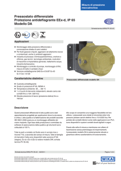
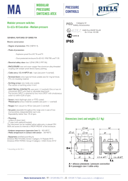
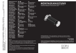
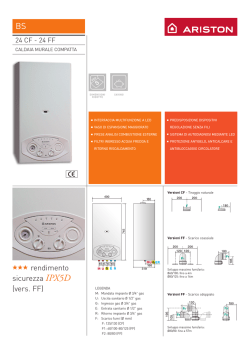
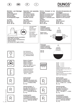
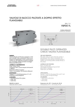
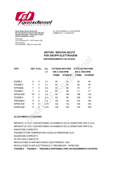
ESEMPIO DI INSTALLAZIONE (RG/2MCS)
Riduttore di pressione per gas con otturatore compensato ad azione diretta. Può essere dotato dei seguenti dispositivi di sicurezza e accessori:
Direct-operated gas pressure regulator with compensated obturator. It can be equipped with the following safety devices and accessory:
• OPSO: Dispositivo di blocco per sovrappressione a valle (solo RG/2MBZ): Interrompe l’erogazione quando la pressione in uscita del regolatore supera il valore
di taratura del dispositivo.
• OPSO: Outlet over pressure shut off device (only RG/2MBZ): It stops the gas flow when the regulator outlet pressure goes up the device setting value
• Valvola di sfioro: Scarica all’esterno piccole portate di gas nel caso si verifichino sovrappressioni a valle del regolatore. Tale scarico è convogliabile all’esterno nel
caso di installazioni in ambienti con scarsa ventilazione.
• Relief valve: It vents outside small quantity of gas in case there are downstream regulator overpressure.That exhaust it is convoyed outside in case of installation
in environment with bad ventilation
• UPSO: Dispositivo di blocco di minima pressione a valle (solo RG/2MBZ): interrompe l’erogazione quando la pressione in uscita del regolatore scende al di
sotto del valore di taratura del dispositivo. Interviene anche in caso di mancanza di alimentazione a monte
• UPSO: Outlet under pressure shut off device (only RG/2MBZ): It stops the gas flow when the regulator outlet pressure goes down the device setting value.
It closes even if there is no inlet pressure.
• Presa di pressione in uscita.
• Outlet pressure test point.
INSTALLAZIONE
INSTALLATION
Il regolatore è conforme alla Direttiva 94/9/CE (denominata Direttiva ATEX 100 a) come apparecchio del gruppo II, categoria 2G e come apparecchio del gruppo II,
categoria 2D; come tale è idoneo per essere installato nelle zone 1 e 21 (oltre che nelle zone 2 e 22) come classificate nell’allegato I alla Direttiva 99/92/CE. Il regolatore
non è idoneo per l’utilizzo nelle zone 0 e 20 come definite nella già citata Direttiva 99/92/CE. Per determinare la qualifica e l’estensione delle zone pericolose si veda la
norma EN 60079-10.
L’ apparecchio, se installato e sottoposto a manutenzione nel pieno rispetto di tutte le condizioni e istruzioni tecniche riportate nel presente documento, non costituisce
fonte di pericoli specifici: in particolare, in condizioni di normale funzionamento, è prevista, da parte del regolatore, l’emissione in atmosfera di sostanza infiammabile
solo occasionalmente.
Il regolatore può essere pericoloso rispetto alla presenza nelle sue vicinanze di altre apparecchiature in caso di intervento della valvola di sfioro integrata o in caso di
rottura delle membrane (di funzionamento (16) e di sicurezza (30) se presente). In quest’ultimo caso (e solo in questo) il regolatore costituisce una sorgente di emissione
di atmosfera esplosiva di grado continuo e, come tale, può originare zone pericolose 0 come definite nella Direttiva 99/92/CE.
In condizioni di installazione particolarmente critica (luoghi non presidiati, carenza di manutenzione, scarsa disponibilità di ventilazione) e, soprattutto in presenza nelle
vicinanze del regolatore di potenziali fonti di innesco e/o apparecchiature pericolose nel funzionamento ordinario in quanto suscettibili di originare archi elettrici o scintille,
è necessario valutare preliminarmente la compatibilità fra il regolatore e tali apparecchiature.
In ogni caso è necessario prendere ogni precauzione utile ad evitare che il regolatore sia origine di zone 0: ad esempio verifica periodica annuale di regolare
funzionamento, possibilità di modificare il grado di emissione della sorgente o di intervenire sullo scarico all’esterno della sostanza esplosiva canalizzando ad esempio
all’esterno lo scarico della valvola si sfioro.
The regulator is in conformity with the Directive 94/9/CE (said Directive ATEX 100 a) as device of group II, category 2G and as device of group II, category 2D; for this
reason it is suitable to be installed in the zones 1 and 21 (besides in the zones 2 and 22) as classified in the attachment I to the Directive 99/92/EC. The regulator is
not suitable to be used in zones 0 and 20 as classified in the already said Directive 99/92/EC. To determine the qualification and the extension of the dangerous zones,
see the norm EN 60079-10.
The device, if installed and serviced respecting all the conditions and the technical instructions of this document, is not source of specific dangers: in particular, during
the normal working, is forecast, by the regulator, the emission in the atmosphere of inflammable substance only occasionally.
ATTENZIONE: le operazioni di installazione/manutenzione devono essere eseguite da personale qualificato.
WARNING: all installation/maintenance work must be carried out by skilled staff.
•
•
•
•
•
•
•
•
•
•
•
•
•
•
•
•
•
•
•
•
•
•
•
•
Impiego
Attacchi flangiati PN16
Su richiesta attacchi flangiati ANSI 150
Pressione max esercizio
Temperatura ambiente
Temperatura superficiale max
Classe accuratezza P2 (AC)
Gruppo accuratezza blocco sovrapressione (AG)
Classe pressione di chiusura (SG)
Campo pressione intervento
Tempo di chiusura blocco
Valvola di sfioro
Connessione dello sfioro
Resistenza meccanica
Fattore di sicurezza
: Gas non aggressivi delle 3 famiglie (gas secchi)
: DN 65 - DN 80 - DN 100 secondo ISO 7005
: 5 bar
: -20 ÷ +60 °C
: 60 °C
: 10
: 10
: 30
: vedere tabella molle di regolazione
:<1s
: testata secondo indicazioni riportate su EN 334
: G 3/4”
: Gruppo 2 (secondo EN 13611:2007)
: f=4 (5*4 = 20 bar) secondo EN 88-2 punto 7.2
•
•
•
•
•
•
•
•
•
•
•
•
•
•
•
range OPSO (mbar)
13 ÷ 27
40 ÷ 110
7 ÷ 15
RB08Z
X10
15 ÷ 50
RB08Z
110
22 ÷ 50
40 ÷ 110
15 ÷ 25
RB08Z
X20
15 ÷ 50
RB08Z
120
50 ÷ 130
90 ÷ 210
25 ÷ 70
RB08Z
X30
15 ÷ 50
RB08Z
130
110 ÷ 200
180 ÷ 350
70 ÷ 110
RB08Z
X40
20 ÷ 100
RB08Z
200 ÷ 350#
300 ÷ 600
70 ÷ 110
RB08Z
X50
-
13 ÷ 27
/
/
RCS080000
X10
15 ÷ 50
RCS080000
110
22 ÷ 50
/
/
RCS080000
X20
15 ÷ 50
RCS080000
120
50 ÷ 130
/
/
RCS080000
X30
15 ÷ 50
RCS080000
130
110 ÷ 200
/
/
RCS080000
X40
15 ÷ 50
RCS080000
140
170 ÷ 400*
/
/
RCS080055
X50
40 ÷ 200
RCS080055
150
300 ÷ 530*
/
/
RCS080055
X60
40 ÷ 200
RCS080055
160
530 ÷ 1300*
/
/
RCS080055
X70
40 ÷ 200
RCS080055
170
800 ÷ 1500*
/
/
RCS080055
X80
40 ÷ 200
RCS080055
13 ÷ 27
40 ÷ 110
7 ÷ 15
RB09Z
X10
15 ÷ 50
RB09Z
110
utenza
user
pipe
ESEMPIO DI INSTALLAZIONE (RG/2MBZ)
INSTALLATION EXAMPLE (RG/2MBZ)
Valvola a sfera
Ball valve
rete
Use
Flanged connections PN 16
On request ANSI 150 flanged connections
Max. working pressure
Environment temperature
Max superficial temperature
P2 accuracy class (AC)
Overpressure lockout accuracy group (AG)
Closing pressure class (SG)
Trip pressure range
Shut off closure time
Relief valve
Relief valve connection
Mechanical strength
Safety factor
: Not aggressive gases of the 3 families (dry gases)
: DN 65 - DN 80 - DN 100 according to ISO 7005
:
:
:
:
:
:
:
:
:
:
:
:
5 bar
-20 ÷ +60 °C
60 °C
10
10
30
see regulation springs table
<1s
tested according to EN 334
G 3/4”
Group 2 (according to EN 13611:2007)
f=4 (5*4 = 20 bar) according to EN 88-2 point 7.2
RIARMO MANUALE (solo RG/2MBZ):
MANUAL RESET (only RG/2MBZ):
Per riarmo del dispositivo di blocco occorre seguire le indicazioni riportate nello schema rappresentato in fig. 6.
A operazione di riarmo terminata si deve tirare lentamente verso il basso il perno di riarmo (25) (per evitare che sia a contatto con il perno di riarmo interno).
In order to reset the shut off device, you need to follow the instructions mentioned in the schedule you may find on fig. 6.
When the reset operation must be completed slowly pull down the reset pin (25) (to avoid any contact with the internal reset pin).
TARATURA ! I modelli RG/2MCS non sono dotate di blocchi di sicurezza.
CALIBRATION ! RG/2MCS models don’t have safety shut off device.
• Prima di avviare l’impianto, assicurarsi che la molla in dotazione al regolatore sia adeguata alla pressione di regolazione voluta.
• Munirsi di un adeguato manometro per il controllo della pressione a valle del regolatore.
• Per le versioni con sfioro (vedi fig. 2 e 5) munirsi di una chiave esagonale a tubo da 10 mm (chiave commerciale) con Ø est. max non superiore a
15mm.
• Per le versioni con sfioro (vedi fig. 3) munirsi di una chiave esagonale a tubo da 8 mm (chiave commerciale) con Ø est. max non superiore a
12mm.
• Before starting the system, pay attention that the standard regulation spring is suitable with the needed regulation pressure.
• Get a proper pressure gauge to check the regulator pressure.
• On versions with relief valve (see fig. 2 and 5) get a commercial spanner, this one has to be an hex with a pipe type of 10 mm and a maximum external
Ø not over than 15 mm.
• On versions with relief valve (see fig. 3) get a commercial spanner, this one has to be an hex with a pipe type of 8 mm and a maximum external Ø not
over than 12 mm.
Nel caso sia necessario effettuare la taratura:
Where it is needed to set the devices:
140
-
180
15 ÷ 25
RB09Z
X20
15 ÷ 50
RB09Z
120
90 ÷ 210
25 ÷ 70
RB09Z
X30
15 ÷ 50
RB09Z
130
110 ÷ 200
180 ÷ 350
70 ÷ 110
RB09Z
X40
20 ÷ 100
RB09Z
200 ÷ 350#
300 ÷ 600
70 ÷ 110
RB09Z
X50
-
13 ÷ 27
/
/
RCS090000
X10
15 ÷ 50
RCS090000
110
22 ÷ 50
/
/
RCS090000
X20
15 ÷ 50
RCS090000
120
50 ÷ 130
/
/
RCS090000
X30
15 ÷ 50
RCS090000
130
110 ÷ 200
/
/
RCS090000
X40
15 ÷ 50
RCS090000
140
170 ÷ 400*
/
/
RCS090055
X50
40 ÷ 200
RCS090055
150
300 ÷ 530*
/
/
RCS090055
X60
40 ÷ 200
RCS090055
160
530 ÷ 1300*
/
/
RCS090055
X70
40 ÷ 200
RCS090055
170
800 ÷ 1500*
/
/
RCS090055
X80
40 ÷ 200
RCS090055
13 ÷ 22
40 ÷ 110
7 ÷ 15
RB10Z
X10
15 ÷ 50
RB10Z
110
140
-
180
18 ÷ 40
40 ÷ 110
15 ÷ 25
RB10Z
X20
15 ÷ 50
RB10Z
120
35 ÷ 120
90 ÷ 210
25 ÷ 70
RB10Z
X30
15 ÷ 50
RB10Z
130
110 ÷ 200
180 ÷ 350
70 ÷ 110
RB10Z
X40
20 ÷ 100
RB10Z
200 ÷ 350#
300 ÷ 600
70 ÷ 110
RB10Z
X50
-
13 ÷ 22
/
/
RCS100000
X10
15 ÷ 50
RCS100000
110
18 ÷ 40
/
/
RCS100000
X20
15 ÷ 50
RCS100000
120
35 ÷ 120
/
/
RCS100000
X30
15 ÷ 50
RCS100000
130
110 ÷ 200
/
/
RCS100000
X40
15 ÷ 50
RCS100000
140
170 ÷ 400*
/
/
RCS100055
X50
40 ÷ 200
RCS100055
150
300 ÷ 530*
/
/
RCS100055
X60
40 ÷ 200
RCS100055
160
530 ÷ 1300*
/
/
RCS100055
X70
40 ÷ 200
RCS100055
170
800 ÷ 1500*
/
/
RCS100055
X80
40 ÷ 200
RCS100055
180
-
#
140
-
Con membrana rinforzata = With reinforced diaphragm
fig. 6
Riarmo Blocco
INSTRUCTION FOR THE RESET OF SHUT OFF DEVICE ON RG/2MBZ
Codice con sfioro
Code with relief valve
40 ÷ 110
* = pilotato = piloted
ISTRUZIONI PER RIARMO DISPOSITIVO DI BLOCCO SU VERSIONI RG/2MBZ
campo differenziale sfioro (mbar)
differential relief valve range (mbar)
22 ÷ 50
utenza
user
pipe
Codice senza sfioro
Code without relief valve
range UPSO (mbar)
50 ÷ 130
DN 80
The gas supply must be shut off before installation.
Check that the line pressure DOES NOT EXCEED the maximum pressure stated on the product label.
The regulator is normally installed before the user. It must be installed with the arrow on the body (5) towards the user.
It can be installed in any position but it is preferable the installation with the spring in vertical position (see fig. 1, 2 ,3 ,4 and 5). Outside the regulator and downstream
of it there is a checking pressure-tap (12) for the control of the regulation pressure.
Connect the G3/8” connection pulse tap (4) to downstream regulator pipe. On RG/2MBZ you have to connect together with the impulse grip (4) the tap outlet as
well (21) (please see installation examples).
Canalize outside the relief valve discharge (18) (if there is). Please see installation examples.
During installation take care not to allow debris or scraps of metal to enter the device.
Check that the inlet and outlet counterflanges are perfectly parallel to avoid unnecessary mechanical stresses on the body of the device. Also calculate the space
needed to fit the seal. If the gap left after the seal is fitted is too wide, do not try to close it by over-tightening the device’s bolts.
Always check that the system is gas-tight after installation.
TECHNICAL DATA
CARATTERISTICHE TECNICHE
rete
The regulator can be dangerous as regards to the presence close to it of other devices when the integrated relief valve vents or in case of damage of the diaphragms
(working one (16) and safety one (30) if there is).
Only in this last case the regulator is a source of emission of the continue degree explosive atmosphere and, so, it can originate dangerous areas 0 as defined in the
99/92/EC Directive. In conditions of particularly critic installation (places not protected, lack of servicing, lacking availability of ventilation) and, especially in presence,
close to the regulator, of potential sources of primer and/or dangerous devices during the normal working because susceptible to origine electric arcs or sparks, it is
necessary to value before the compatibility between the regulator and these devices.
In any case it is necessary to take any useful precaution to avoid that the regulator could be origin of areas 0: for example yearly periodical inspection of regular working,
possibility to change the emission degree of the source or to attend on the exhaust outside the explosive material canalizing outside, for example, the relief
valve discharge.
•
•
•
•
P2
(mbar)
DN 100
•
E’ necessario chiudere il gas prima dell’installazione.
Verificare che la pressione di linea NON SIA SUPERIORE alla pressione massima dichiarata sull’etichetta del prodotto.
Il regolatore è normalmente posizionato prima dell’utenza. Deve essere installato con la freccia in rilievo sul corpo (5) rivolta verso l’utenza.
Può essere installato in qualsiasi posizione anche se è preferibile l’installazione con la molla (3) in verticale (come in figura 1, 2 ,3 ,4 e 5). All’esterno del regolatore
e a valle dello stesso è sistemata una presa di pressione (12) per il controllo della pressione di regolazione.
Collegare la presa di impulso (4) con attacco G3/8” a valle del regolatore. Su RG/2MBZ, collegare insieme alla presa d’impulso (4) anche l’uscita del rubinetto (21)
(vedi esempio di installazione).
Canalizzare all’esterno lo scarico (18) della valvola di sfioro (se presente). Vedi esempi di installazione.
Durante l’installazione evitare che detriti o residui metallici penetrino all’interno dell’apparecchio.
Verificare che le controflange di ingresso e uscita siano perfettamente parallele per evitare di sottoporre il corpo a inutili sforzi meccanici, calcolare inoltre lo spazio
per l’inserimento della guarnizione di tenuta. Se a guarnizioni inserite lo spazio rimanente è eccessivo non cercare di colmarlo stringendo eccessivamente i bulloni
dell’apparecchio.
In ogni caso dopo l’installazione verificare la tenuta dell’impianto.
Attacco
Connections
DN 65
DESCRIPTION
•
•
•
•
CARATTERISTICHE MOLLE DI REGOLAZIONE - REGULATION SPRINGS DATA
INSTALLATION EXAMPLE (RG/2MCS)
DESCRIZIONE
Shut-Off Reset
RISULTATI DAL TEST DI STABILIZZAZIONE (PORTATA IN Nm3/h DI GAS NATURALE)
RESULTS FROM STABILIZATION TEST (FLOW RATES IN Nm3/h OF NATURAL GAS)
Chiudere la valvola a sfera a valle del regolatore
DN 65
Close the ball valve downstream of the regulator
nelle versioni RG/2MCS si deve tarare nell’ordine: P2 - Sfioro
nelle versioni RG/2MBZ si deve tarare nell’ordine: UPSO - OPSO - P2 - Sfioro
Valvola a sfera
Ball valve
Chiudere rubinetto blocco (21)
Close the shut off tap (21)
Premere il pulsante by-pass (28)
Push the by-pass button (28)
in RG/2MCS versions setting must be with the following order: P2 - Relief
in RG/2MBZ versions setting must be with the following order: UPSO – OPSO - P2 - Relief
Riarmare premendo il perno (25) (vedi fig. 5)
La taratura della P2 va eseguita con l’impianto in portata.
The P2 setting mus be carried out during plant under flow.
Prima di avviare l’impianto, nelle versioni con sfioro, svitare e rimuovere il tappo (1) e avvitare al massimo il dado di regolazione sfioro (19).
Before starting the system, on versions with relief valve, unscrew and remove the cap (1) and screw at the maximum the relief regulation nut (19).
Prima di avviare l’impianto, solo nelle versioni con blocchi di sicurezza RG/2MBZ:
Before starting the system, only on versions with safety shut off RG/2MBZ:
• Svitare il tappo del blocco (23).
• Unscrew the shut off cap (23).
• Svitare e rimuovere la parte finale del perno di riarmo (25).
• Unscrew and remove the final part of the reset pin (25).
• Con apposita chiave (29) avvitare al massimo la vite di regolazione OPSO (24) e posizionare al minimo la vite di regolazione UPSO (26).
• By the special tool (29) screw completely the OPSO regulation screw (24) and put at minimum the UPSO regulation screw (26).
ESEMPIO taratura P2 / OPSO / UPSO / SFIORO
•
•
•
•
Pressione necessaria di regolazione P2=20 mbar
Intervento blocco max (OPSO) = 40 mbar
Intervento valvola di sfioro = 30 mbar
Intervento blocco min (UPSO) = 10 mbar
• SETTAGGIO P2:
•
•
•
•
Needed regulation pressure 20 mbar
Maximum shut off (OPSO) intervention 40 mbar
Relief valve intervention 30 mbar
Minimum shut off (UPSO) intervention 10 mbar
• P2 CALIBRATION:
• Avviare l’impianto e controllando la pressione P2, regolare (avvitando o svitando) la vite di taratura (2) fino alla pressione voluta (in questo caso
20 mbar). A fine operazione riavvitare il tappo (1) nella posizione originale.
• Start the system and checking the pressure P2, regulate (screwing or uncrewing) the regulation screw (2) up to the needed pressure (in this
specific case to 20 mbar). When the regulator is set, rescrew the cap (1) in the original position.
• Reset the shut off device following the instructions stated on the paragraph “MANUAL RESET”.
• Leggendo sul manometro, svitare la vite di regolazione (2) fino alla pressione P2 voluta , (in questo caso 10 mbar).
• Reading on the pressure gauge, unscrew the regulation screw (2) till you reach the P2 pressure needed (in this case 10 mbar).
• Avvitare, con la chiave (29), la vite di regolazione UPSO (26) fino all’intervento del blocco di minima pressione che a questo punto è tarato a 10 mbar.
• Screw, by the special tool (29), the UPSO regulation screw (26), till the minimum shut off pressure tripping, which, now is setted to 10 mbar.
• OPSO CALIBRATION:
• Avvitare di qualche giro la vite di regolazione P2 (2) e riarmare il dispositivo di blocco. Avvitare la vite di regolazione (2) fino alla pressione P2
voluta (in questo caso 20 mbar) controllandola sul manometro.
• Make some crackdown on P2 regulation screw (2) and reset the shut off device. Screw the regulation screw (2) till you reach the P2 pressure
needed (in this case 20 mbar) checking it on the pressure gauge.
• Premendo con la chiave a tubo sul dado di regolazione (19), aumentare la pressione P2, leggendola sul manometro, fino al valore di taratura
OPSO voluto (arrivare in questo caso a 40 mbar).
• Push with the commercial spanner on the regulation nut (19), increasing the P2 pressure, reading on the pressure gauge, till the
needed setting value OPSO (in this specific case to 40 mbar).
• Contemporaneamente svitare lentamente, con la chiave (29), la vite di regolazione (24) fino all’intervento del dispositivo di blocco di massima
pressione. Avvitare la vite (24) di ¼ di giro. A questo punto il blocco OPSO è tarato a 40 mbar.
• In the meanwhile, by the special tool (29), slowly unscrew the regulation screw (24) till the maximum pressure shut off device tripping. Screw
the screw (24) ¼ turn. At this point the shut off OPSO is setted to 40 mbar.
• Riarmare il dispositivo di blocco
• Reset the shut off device
• RELIEF VALVE CALIBRATION:
• Chiudere lentamente il rubinetto a valle del regolatore.
• Slowly close the tap downstream the regulator.
• Premendo con la chiave a tubo idonea sul dado di regolazione sfioro (19), aumentare la pressione P2, leggendola sul manometro, fino al valore
di taratura di sfioro voluto (arrivare in questo caso a 30 mbar).
• Pushing with the appropriate spanner on the regulation nut (19), increase the P2 pressure, reading on the pressure gauge, till the needed relief setting
value (in this case to 30 mbar).
• Senza premere ulteriormente, svitare lentamente il dado di regolazione sfioro (19) finche la pressione P2, visualizzata sul manometro, inizia a diminuire.
• Without pushing, slowly unscrew the regulation screw (19) till the P2 pressure, showed on the pressure gauge, starts to decrease.
• Lo sfioro è in questo caso tarato a 30 mbar
• The relief, in this case, is setted at 30 mbar.
• Rimuovere la chiave a tubo e richiudere il tappo (1), nelle versioni RG/2MBZ richiudere anche il tappo (23).
• Remove the spanner and close the cap (1), on RG/2MBZ versions also close the cap (23).
Le operazioni suddette devono essere eseguite esclusivamente da tecnici qualificati.
Slowly open the ball valve downstream the regulator
Riarmare premendo il perno (25) (vedi fig. 5)
Reset pushing the pin (25) (see fig. 5)
NO
Riarma?
The above-said operations must be carried out only by qualified technicians.
P2 = 30 mbar
P2 = 50 mbar
P2 = 100 mbar
1000
1100
1090
1100
1050
1 bar
1490
1240
1450
1670
1600
2 bar
1800
2125
1850
2100
2400
3 bar
1625
2230
2230
2250
2600
4 bar
1670
1380
2400
2400
2700
5 bar
1750
1480
1850
1950
2850
P1
P2 = 20 mbar
P2 = 30 mbar
Aprire il rubinetto del blocco (21)
Open the shut off tap (21)
Aprire la valvola a sfera a valle del regolatore
P2 = 50 mbar
P2 = 100 mbar
P2 = 200 mbar
500 mbar
1350
1450
1240
1350
1240
1 bar
1950
2150
2100
2350
2200
2 bar
2450
2650
3100
3450
3400
3 bar
2450
2600
2850
3450
3900
4 bar
2450
2700
3100
3700
3900
5 bar
2600
2700
3200
3840
4000
P2 = 200 mbar
DN 100
YES
Open the ball valve downstream of the regulator
Chiudere rubinetto blocco (21)
Close the shut-off tap (21)
Chiudere la valvola a sfera a valle del regolatore
Close the ball valve downstream of the regulator
Premere pulsante by-pass (28)
Push the by-pass button (28)
Riarmare premendo il perno (25) (vedi fig. 5)
Reset pushing the pin (25) (see fig. 5)
Una volta riarmato, aprire lentamente la
valvola a sfera a valle del regolatore
Once rearmed, slowly open the ball valve
downstream of the regulator
Aprire il rubinetto del blocco (21)
Open the shut-off tap (21)
Aprire lentamente la valvola a sfera a valle del regolatore
Slowly open the ball valve downstream of the regulator
P2 = 200 mbar
DN 80
Does it reset?
• UPSO CALIBRATION:
• Riarmare il dispositivo di blocco seguendo le istruzioni indicate nel paragrafo “RIARMO MANUALE”.
• SETTAGGIO SFIORO:
Aprire lentamente la valvola a sfera a valle
del regolatore
Aprire rubinetto blocco (21)
P2 = 20 mbar
YES
Riarma?
Does it reset?
EXAMPLE of P2 / OPSO / UPSO / RELIEF setting
• On versions with relief valve (see fig. 2 and 5) you must act directly on the adjustment regulation screw (2); on versions without relief valve (see fig.
1 and 4) before to proceed you have to unscrew the cap (1). On versions with pilot system (fig. 3) it is necessary to unscrew the cap (1) in any case.
• SETTAGGIO OPSO:
NO
Open the shut off tap (21)
• nelle versioni con sfioro (fig. 2 e 5) si deve agire direttamente sulla vite di regolazione (2); nelle versioni senza sfioro (fig. 1 e 4) è necessario,
prima di procedere, svitare il tappo (1). Nelle versioni pilotate (fig. 3) è necessario svitare il tappo (1) in ogni caso.
• SETTAGGIO UPSO:
Reset pushing the pin (25) (see fig. 5)
P1
500 mbar
P1
P2 = 20 mbar
P2 = 30 mbar
P2 = 50 mbar
P2 = 100 mbar
500 mbar
1670
1500
1500
1700
1270
1 bar
2400
2400
2480
2400
2300
2 bar
3100
3200
3700
3800
3700
3 bar
3800
3800
4900
5000
5000
4 bar
3800
3800
4900
5000
5000
5 bar
3800
3800
4900
5000
5000
REGOLATORE (RG/2MCS)
REGULATOR (RG/2MCS)
REGOLATORE CON BLOCCHI DI SICUREZZA (RG/2MBZ)
REGULATOR WITH SAFETY SHUT OFF (RG/2MBZ)
Dimensioni di ingombro in mm
Overall dimensions in mm
fig. 4
senza sfioro
without relief valve
fig. 1
senza sfioro
without relief valve
Via Moratello, 5/6/7 - 37045
Z.A.I. Legnago (VR) Italy
www.madas.it
Attacchi
Connections
A
B
C
D
RG/2MCS DN 65
290
471
-
330
RG/2MCS DN 65*
290
518
-
330
RG/2MBZ DN 65
290
471
545
330
RG/2MCS DN 80
310
478
-
330
RIDUTTORI DI PRESSIONE PER GAS CON REGOLATORE
COMPENSATO AD AZIONE DIRETTA TIPO RG/2MCS - RG/2MBZ
DIRECT OPERATED GAS PRESSURE REGULATOR WITH
COMPENSATED OBTURATOR TYPE RG/2MCS - RG/2MBZ
RG-2MCS - RG-2MBZ
Conforme Direttiva 2009/142/CE (Direttiva Gas)
Conforme EN 88.2 - EN 334
Conforme Direttiva 97/23/CE (Direttiva PED)
Conforme Direttiva 94/9/CE (Direttiva ATEX)
In conformity with the 2009/142/EC Directive (Gas Directive)
In conformity with EN 88.2 - EN 334
In conformity with the 97/23/EC Directive (PED Directive)
In conformity with the 94/9/EC Directive (ATEX Directive)
RG/2MBZ
fig. 5
con sfioro
with relief valve
fig. 2
con sfioro
with relief valve
RG/2MCS DN 80*
310
525
-
330
RG/2MBZ DN 80
310
478
545
330
RG/2MCS DN 100
350
504
-
330
RG/2MCS DN 100*
350
551
-
330
RG/2MBZ DN 100
350
504
561
330
RG/2MCS
II 2G - II 2D
* = pilotato = piloted
MADAS-03
29
MADE IN ITALY
0497
REGOLATORE PILOTATO (RG/2MCS)
PILOTED REGULATOR (RG/2MCS)
fig. 3
fig. 4, 5
1.
2.
3.
4.
5.
6.
7.
8.
9.
10.
11.
12.
13.
14.
15.
16.
17.
18.
19.
20.
30.
1.
2.
3.
4.
5.
6.
7.
8.
9.
10.
11.
12.
13.
14.
15.
16.
17.
18.
19.
20.
1.
2.
3.
4.
5.
6.
7.
8.
9.
10.
11.
12.
13.
14.
15.
16.
17.
18.
19.
20.
21.
22.
23.
24.
25.
26.
27.
28.
29.
30.
Tappo di chiusura
Vite regolazione P2
Molla regolazione P2
Raccordo tubetto sensore esterno
Corpo
Otturatore regolatore
Viti fissaggio fondello
O-Ring di tenuta
Fondello
Dado di fissaggio
Tubo sensore
Presa di pressione in uscita
Perno centrale
Membrana di compensazione
Disco per membrana
Membrana di funzionamento
Molla valvola sfioro
Tappo antipolvere/scarico valvola sfioro
Dado per taratura sfioro
Imbuto
Membrana di sicurezza
Tappo di chiusura
Vite regolazione P2
Molla regolazione P2
Raccordo tubetto sensore esterno
Corpo
Otturatore regolatore
Viti fissaggio fondello
O-Ring di tenuta
Fondello
Dado di fissaggio
Tubo sensore
Presa di pressione in uscita
Perno centrale
Membrana di compensazione
Disco per membrana
Membrana di funzionamento
Molla valvola sfioro
Tappo antipolvere/scarico valvola sfioro
Dado per taratura sfioro
Imbuto
Tappo di chiusura (regolatore)
Vite regolazione P2
Molla regolazione P2
Raccordo tubetto sensore esterno
Corpo
Otturatore regolatore
Viti fissaggio fondello
O-Ring di tenuta
Fondello
Dado di fissaggio
Tubo sensore
Presa di pressione in uscita
Otturatore (blocco)
Membrana di compensazione
Disco per membrana
Membrana di funzionamento
Molla valvola sfioro
Tappo antipolvere/scarico valvola sfioro
Dado per taratura sfioro
Imbuto
Rubinetto
Molla blocco max (OPSO)
Tappo di chiusura (blocco)
Vite taratura blocco max (OPSO)
Riarmo del dispositivo di blocco
Vite taratura blocco min (UPSO)
Molla blocco min (UPSO)
Pulsante by-pass
Chiave speciale
Membrana di sicurezza
fig. 1, 2
fig. 3
fig. 4, 5
1.
2.
3.
4.
5.
6.
7.
8.
9.
10.
11.
12.
13.
14.
15.
16.
17.
18.
19.
20.
30.
1.
2.
3.
4.
5.
6.
7.
8.
9.
10.
11.
12.
13.
14.
15.
16.
17.
18.
19.
20.
1.
2.
3.
4.
5.
6.
7.
8.
9.
10.
11.
12.
13.
14.
15.
16.
17.
18.
19.
20.
21.
22.
23.
24.
25.
26.
27.
28.
29.
30.
Closing cap
P2 calibration screw
P2 regulation spring
External sensing line connection
Body
Obturator of regulator
Bottom fixing screws
Seal O-Ring
Bottom
Fixing nut
Sensor tube
Outlet pressure test nipple
Central pin
Compensation diaphragm
Diaphragm disc
Working diaphragm
Relief valve spring
Antidust cap/relief valve discharge
Nut for relief valve calibration
Funnel
Safety diaphragm
Closing cap
P2 calibration screw
P2 regulation spring
External sensing line connection
Body
Obturator of regulator
Bottom fixing screws
Seal O-Ring
Bottom
Fixing nut
Sensor tube
Outlet pressure test nipple
Central pin
Compensation diaphragm
Diaphragm disc
Working diaphragm
Relief valve spring
Antidust cap/relief valve discharge
Nut for relief valve calibration
Funnel
Closing cap (regulator)
P2 calibration screw
P2 regulation spring
External sensing line connection
Body
Obturator of regulator
Bottom fixing screws
Seal O-Ring
Bottom
Fixing nut
Sensor tube
Outlet pressure test nipple
Obturator (shut off)
Compensation diaphragm
Diaphragm disc
Working diaphragm
Relief valve spring
Antidust cap/relief valve discharge
Nut for relief valve calibration
Funnel
Tap
OPSO spring
Closing cap (shut off)
OPSO calibration screw
Reset of shut off device
UPSO calibration screw
UPSO spring
By-pass button
Special tool
Safety diaphragm
Mod. MADAS IT/270.00
fig. 3
fig. 1, 2
Via Moratello, 5/6/7 - 37045 Z.A.I. Legnago (VR) Italy
Tel. +39 0442/23289 - Fax +39 0442/27821 - http://www.madas.it - e-mail: [email protected]
© Copyright 2026 Paperzz