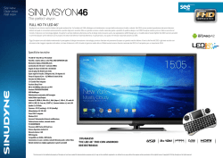
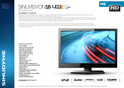
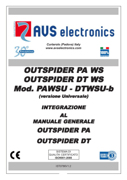
DBC 01 DBC 03 - DBC 04 FOTOCELLULA CORDLESS I Descrizione dispositivi Progettato e costruito interamente dalla CAME Cancelli Automatici S.p.A. Garantito 24 mesi salvo manomissioni DBC 01 Dispositivo do protezione composto da due unità: MANUALE D’INSTALLAZIONE “ISTRUZIONI IMPORTANTI PER LA SICUREZZA DURANTE L’INSTALLAZIONE” ATTENZIONE: L’INSTALLAZIONE NON CORRETTA PUÒ CAUSARE GRAVI DANNI SEGUIRE TUTTE LE ISTRUZIONI DI INSTALLAZIONE IL PRESENTE MANUALE È DESTINATO SOLAMENTE A INSTALLATORI PROFESSIONALI O A PERSONE COMPETENTI. Legenda simboli Questo simbolo segnala parti da leggere con attenzione. Questo simbolo segnala parti riguardanti la sicurezza. Questo simbolo segnala le note da comunica all’utente. -Ricevitore a infrarossi 12/24V AC/DC. 1 led di segnalazione batteria scarica (quando il led lampeggia sul ricevitore, segnala che le batterie del trasmettitore hanno ancora un’autonomia di circa un mese) -Trasmettitore a infrarossi alimentato a batterie (4 batterie da 1.5V AAA) DBC 03 - Ripetitore a infrarosso, composto da un fotodiodo ricevente centrale e due fotodiodi trasmittenti laterali, con dip selezione lato di emissione. Alimentato a batterie (4 batterie da 1.5V AAA) Riferimenti normativi Per il prodotto in oggetto sono state considerate le seguenti normative di riferimento: EN 12978, UNI EN 954-1, CEI EN 60335-1, UNI EN 12453. RX RX TX DBC 04 - Ripetitore a infrarosso, composto da un fotodiodo trasmittente centrale e due fotodiodi riceventi laterali, con dip [per] selezione lato di ricezione. Alimentato a batterie (4 batterie da 1.5V AAA) TX TX RX Dati tecnici Installazione DBC 01 (TX) • Verificare che il punto di fissaggio dell’apparecchiatura- sia in una zona protetta dagli urti, che le superfici di ancoraggio siano solide, e che il fissaggio venga fatto con elementi idonei (viti, tasselli, ecc) alla superficie. • Predisporre tubazioni e canaline adeguate per il passaggio dei cavi elettrici garantendone la protezione contro il danneggiamento meccanico. Descrizione/Collegamenti elettrici e funzioni DIP + R15 - + 05 06 07 08 09 V1 V2 V3 AAA + 1,5V AAA # 2 K Ripetitore DBC 04 K Alimentazione: (4 batterie da 1.5V AAA) Assorbimento : 70 µA Grado di protezione: IP54 Materiale:PC-ABS UL94V0 / Policarbonato / Marpram mar TPA1 65 NT # Temperatura di esercizio: Fig.B 1 DBC 01 (RX) 2 Dimensioni e interassi fori Ricevitore/Trasmettitore /Ripetitore K Fig.A # - 1,5V R23 + 1-Alloggiamento batterie (4 batterie da 1.5V AAA) 2-Led ad infrarosso + R22 - - - RipetitoreDBC 03 Alimentazione: (4 batterie da 1.5V AAA) Assorbimento : 70 µA Grado di prot ezione: IP54 Materiale:PC-ABS UL94V0 / Policarbonato / Marpram mar TPA1 65 NT # Temperatura di esercizio: + 1 DBC 01 (TX) # R13 # DBC 01 (RX) Alimentazione: 12/ 24 V A.C. - D.C. Assorbimento : 48 mA Grado di protezione: IP54 Materiale:PC-ABS UL94V0 / Policarbonato / Marpram mar TPA1 65 NT # Temperatura di esercizio: Prima di procedere all’installazione è necessario: • Assicurarsi che la tensione di linea sia scollegata. 1 2 3 4 5 6 7 8 9 10 11 12 Alimentazione: (4 batterie da 1.5V AAA) Assorbimento : 70 µA Grado di protezione: IP54 Materiale:PC-ABS UL94V0 / Policarbonato / Marpram mar TPA1 65 NT # Temperatura di esercizio: 10 2 TS 2 1-Led di segnalazione presenza segnale 2-Dip Switch Funzione Dip Dip 1 in ON = 3 alimentazione 12 V AC/DC Dip 1 in OFF = alimentazione 24 V AC/DC Dip 2 in OFF = 4 Esclusione test servizi (da utilizzare quando non viene colleggato TS) NO 3-Led Segnalazione NC Batteria scarica e Contatto N.O. C contatto aperto C1/C2/C3/C4 4-Morsettiera di collegamento. + 1-Alloggiamento batterie (4 batterie da 1.5V AAA) 2-Led ad infrarossi selezionabili tramite DIP 3- Led segnalazione batteria scarica 4-Dip di selezione led di trasmissione 1 DBC01(RX) DBC04* Dip n°1 ON led SX attivo Dip n°2 ON led DX attivo 2 K K DBC01(TX) - + + - + - Ripetitore DBC03 DBC03* K 3 1 2 * Con colonnine DB-L/DB-LN 4 DBC01(TX) DBC01(RX) DBC04 NON necessita NON necessita Dip n°1 in ON configurazione configurazione Dip n°2 in OFF Ripetitore DBC04 + 2 K K 1-Alloggiamento batterie (4 batterie da 1.5V AAA) 2-Led ad infrarossi selezionabili tramite DIP 3- Led segnalazione batteria scarica 4-Dip di selezione led di trasmissione - + + - + - 1 K Dip n°1 ON led SX attivo Dip n°2 ON led DX attivo 3 1 2 4 Esempio applicativo di impianto e relativa configurazione Dip Switch DBC01(TX) DBC04* DBC01(TX)* NON necessita configurazione DBC01(RX) NON necessita configurazione DBC03* DBC01(RX)** * Con colonnine DB-L/DB-LN ** Con supporto fotocellula G02802 DBC04 Dip n°1 in ON Dip n°2 in OFF DBC03 Dip n°1 in OFF Dip n°2 in ON DBC03 Dip n°1 in OFF Dip n°2 in ON N.B. Quando si utilizza DBC01, DBC03 e DBC04 come rappresentato nei due schemi precedenti ricordarsi di togliere il ponticello su DBC01 (TX) Montaggio • Verificare che la distanza tra le due fotocellule sia al max di 10 metri e che siano perfettamente in asse, prima di procedere alla loro installazione. • Procedere con il fissaggio dei fondi delle fotocellule, utilizzando: - per le colonnine DB-L, viti UNI 6954 3.9x13 inox (all’interno della confezione DB-L); - per fissaggio a muro o su acciao, viti UNI 6954 3.9x32 con eventuale tasselli , in dotazione. • Inserire le batterie (n° 4 da 1.5V AAA) nel trasmettitore e nei ripetitori rispettando la polarità riportata sulla scheda. • Selezionare i led (ON/OFF) a seconda della morfologia dell’impianto. Eseguire i collegamenti di DBC01 (RX) come da figura a pag. 2. • Chiudere i dispositivi agganciando dall’alto il coperchio e fissandolo con le viti in dotazione. Collegamento DBC 01 con altre fotocellule Dismissione e smaltimento - I componenti dell’imballo (cartone, plastiche etc.) sono assimilabili ai rifiuti solidi urbani e possono essere smaltiti senza alcuna difficoltà, semplicemente effettuando la raccolta differenziata per il riciclaggio. Prima di procedere è sempre opportuno verificare le normative specifiche vigenti nel luogo d’installazione. Altri componenti (schede elettroniche, batterie dei radiocomandi etc.) possono invece contenere sostanze inquinanti. Vanno quindi rimossi e consegnati a ditte autorizzate al recupero e allo smaltimento degli stessi. DBC 01 con DIR 0 2 C1 10 2 C1 DIR DIR 2 TX 10 Tx - 2 NON DISPERDERE NELL’AMBIENTE! TX C NC Dichiarazione del fabbricante Rx Dichiarazione di conformità DIW DIW 24 Rx Tx - 0 TS C NC NO la CAME Cancelli Automatici S.p.A. via Martiri della Libertà, 15 31030 Dosson di Casier - Treviso - ITALY tel (+39) 0422 4940 - fax (+39) 0422 4941 internet: www.came.it - e-mail: [email protected] Dichiarano sotto la propria responsabilità, che i seguenti prodotti per l’automazione di cancelli e porte da garage, cosi denominati: DBC 01 con DOC DBC 01- DBC 03-DBC 04 0 2 C1 10 2 C1 DIW Tx Sono conformi ai requisiti essenziali ed alle disposizioni pertinenti, stabilite dalle seguenti Direttive e alle parti applicabili delle normative di riferimento in seguito elencate: Direttiva Compatibilità Elettromagnetica 2004/108/CE Direttiva Bassa Tensione 2006/95/CE Direttiva Macchine 98/37/CE DIW 24 Rx - 0 TS C NC NO DOC 24 0 24 Tx 0 N0 C NC EN 61000-6-1 EN 61000-6-2 EN 61000-6-3 EN 60335-1 EN 13241-1 L’amministratore delegato Sig. Gianni Michielan Rx Problemi - Il led sul ricevitore lampeggia: la batteria del trasmettitore è scarica - Il Led sul ricevitore rimane acceso: segnale interrotto per un malfunzionamento del trasmettitore. 119RU82 ver 0.1 - 09/2008 DBC 01 DBC 03 - DBC 04 CORDLESS PHOTOCELL GB Description of devices Designed and manufactured by CAME CANCELLI AUTOMATICI S.p.A. in compliance with the safety regulations in force.S.p.A. DBC 01 Protection deviceMade up of two units: INSTALLATION MANUAL “IMPORTANT SAFETY INSTRUCTIONS FOR INSTALLATION” “CAUTION: IMPROPER INSTALLATION MAY CAUSE SERIOUS DAMAGE, FOLLOW ALL INSTALLATION INSTRUCTIONS CAREFULLY” “THIS MANUAL IS ONLY FOR PROFESSIONAL INSTALLERS OR QUALIFIED PERSONS” -12/24v AC/DC Infrared receiver. 1 led to signal that battery is run down (when the led on the receiver flashes, this means that the batteries’ charge will completely run down in about a month) -Battery powered infrared transmitter (works on four 1.5V AAA batteries) Legend of symbols This symbol indicates sections to be read with particular care. This symbol indicates sections concerning safety This symbol indicates notes to communicate to users. DBC 03 - Infrared repeater, made up of a central transmitter photodiode and two lateral receiver photodiodes, with dip switches for selecting receiving side. Battery powered (works on four 1.5 AAA batteries) Reference Standards with the following standards: EN 12978, UNI EN 954-1, CEI EN 60335-1, UNI EN 12453. RX RX TX DBC 04 - Infrared repeater, made up of a central photodiode receiver and two lateral, transmitting photodiodes, with dip switches for selecting the emitting side. Battery powered (works on four 1.5V AAA batteries) TX TX RX Technical data Installation DBC 01 (TX) Power supply: (4 1.5V AAA batteries) Draw: 70 µA Degree of protection: IP 54 Material: PC-ABS UL94V0 / Policarbonato / Marpram mar TPA1 65 NT # Working temperature: # Before installing you must: • Make sure that the line voltage is disconnected. • See that the point, to which the equipment will be mounted, is in an area protected from any impacts, that the mounting surface is solid, and that the mounting on to the surface is carried out DBC 01 (RX) with the proper hardware (bolts, pins, etc). Power supply: 12/ 24 V A.C. - D.C. Draw: 48 mA Degree of protection: IP 54 Material: PC-ABS UL94V0 / Policarbonato / Marpram mar TPA1 65 NT # Working temperature: •Provide for proper electrical cable conduits making sure that they are free from any mechanical damage. + - 05 06 07 08 09 V1 V2 V3 AAA + - 2 K Ripetitore DBC 04 K Power supply: (4 1.5V AAA batteries) Draw: 70 µA Degree of protection: IP 54 Material: PC-ABS UL94V0 / Policarbonato / Marpram mar TPA1 65 NT # Working temperature: Fig.B 1 DBC 01 (RX) 2 Dimensions and holes pitch Receiver/Transmitter/Repeater K Fig.A # R15 # 1 + 1,5V AAA 1,5V + R23 - 1-Battery housing (four 1.5V AAA batteries) 2-Infrared led Power supply: (4 1.5V AAA batteries) Draw: 70 µA Degree of protection: IP 54 Material: PC-ABS UL94V0 / Policarbonato / Marpram mar TPA1 65 NT # Working temperature: - R13 DBC 01 (TX) RipetitoreDBC 03 + 1 2 3 4 5 6 7 8 9 10 11 12 - R22 # + - Description/Electrical connections and DIP switch functions 10 2 TS 2 1-Signal present warning led 2-Dip Switch Dip Switch function Dip switch 1 in ON position= 12V AC/DC power supply 3 Dip switch 1 in OFF position= 24V AC/DC power supply Dip switch 2 in OFF position= Excludes testing of service 4 function (to be used when TS?? Is not connected) NO 3- Low battery/open contact NC warning led Contatto N.O. C 4-Terminal board for conC1/C2/C3/C4 nections + 1-Battery housing (Four 1.5V AAA batteries) 2-Infrared led, selectable through the DIP switch 3-Low battery warning led 4-Dip switch for selecting transmission led 1 When Dip switch 1 ON, left-hand led is active When Dipswitch 2 ON, right-hand led is active 2 K K K 3 1 2 4 + 1-Battery housing (Four 1.5V AAA batteries) 2-Infrared led, selectable through the DIP switch 3-Low battery warning led 4-Dip switch for selecting transmission led - + + - + - 1 2 K K 3 1 DBC 01(RX) DBC 04* When Dip switch 1 ON, left-hand led is active When Dip switch 2 ON, righthand led is active 2 4 Example of a standard installation and relative Dip Switch configuration DBC 01(TX) DBC 04* Does NOT require DBC 01(TX)* configuration DBC 01(RX) Does NOT require configuration DBC 03* DBC 01(RX)** *With DB-L/DB-LN columns **With G02802 photocell support DBC 03* *With DB-L/DB-LN columns DBC 01(TX) Does NOT require configuration DBC 04 Repeater K DBC 01(TX) - + + - + - DBC 03 Repeater DBC 04 Dip 1 set to ON Dip 2 set to OFF DBC 03 Dip 1 set to OFF Dip 2 set to ON DBC 01(RX) Does NOT require configuration DBC 04 DBC 03 Dip 1 set to ON Dip 1 set to OFF Dip 2 set to OFF Dip 2 set to ON Note: When using DBC 01, DBC 03 and DBC 04, as explained in the two preceding configurations, remember to remove the bridge on DBC 01 (TX) Assembly • Verificare Make sure that the distance between the two photocells is not greater than 10 metres, and that they are perfectly aligned, before installing. • Fix the bottoms of the photocells as follows: - for the DB-L posts, use the UNI 6954 3.9x3 stainless steel screws (found in the DB-L kit); - for fixing on the wall or on steel, use the UNI 6954 3.9x32 screws with the supplied nogs . • Insert the batteries (you will need four 1.5V AAAs) into the transmitter and the repeaters making sure the polarity matches that shown on the card. • Set the leds to (ON/OFF) depending on the make up of the system. Connect the DBC01 (RX) as shown in the figure on page 2. • Close the devices by hooking the cover at the top and fixing it in place with the supplied screws . Connecting DBC 01 with DIR/DOC Demolition and disposal Product disposal Our products are made up of various types of materials. Most of them (aluminium, plastics, iron, electrical wires, etc.) may be disposed of in normal garbage collection bins and can be recycled by disposing of in specific recyclable material collection bins and disposal in authorized centres. Other components (electrical boards, remote control batteries, etc.), however, may contain polluting substances. They should therefore be removed and given to qualified service companies for proper disposal. Prior to disposal, it is always advisable to check specific regulations in force in the place of disposal. PLEASE DISPOSE OF PROPERLY! DBC 01 with DIR 0 2 C1 10 2 C1 DIR DIR 2 TX 10 Tx - 2 TX C NC TS C NC NO Rx Manufacturer’s declaration DIW DIW 24 Rx Tx - 0 Declaration of conformity la CAME Cancelli Automatici S.p.A. via Martiri della Libertà, 15 31030 Dosson di Casier - Treviso - ITALY tel (+39) 0422 4940 - fax (+39) 0422 4941 internet: www.came.it - e-mail: [email protected] DBC 01 with DOC Declare under their own responsibility that the following products for gate and garage door automation called: DBC 01- DBC 03-DBC 04 0 2 C1 10 2 C1 DIW Tx DIW 24 Rx - 0 TS 24 0 C NC NO DOC 24 0 Tx N0 C NC Rx Are compliant with essential requirements and with pertinent regulations established by the following directives and to the applicable parts of the standards listed below: Electromagnetic compatibility directive 2004/108/CE Electrical equipment designed for use within certain voltage limits directive 2006/95/CE Machinery directive 98/37/EC L’amministratore delegato EN 61000-6-1 Sig. Gianni Michielan EN 61000-6-2 EN 61000-6-3 EN 60335-1 EN 13241-1 Problems - The led on the receiver is flashing: the transmitter battery is run down - The led on the receiver stays on: signal is interrupted due to transmitter malfunction. 119RU82 ver 0.1 - 09/2008 DBC 01 DBC 03 - DBC 04 PHOTOCELLULES À PILES FR Description des dispositifs Le produit a été conçu et fabriqué par CAME CANCELLI AUTOMATICI S.p.A. Il est garanti 24 mois sauf en cas d’altérations. DBC 01 Dispositif de protection composé de deux unités: MANUEL D’INSTALLATION “CONSIGNES DE SÉCUITÉ IMPORTANTES POUR LE MONTAGE” “ATTENTION: UN MONTAGE INCORRECT PEUT PROVOQUER DE GRAVES DOMMAGES, SUIVRE TOUTES LES INSTRUCTIONS DE MONTAGE” “CE MANUEL EST DESTINÉ EXCLUSIVEMENT AUX INSTALLATEURS PROFESSIONNELS OU AU PERSONNEL AUTORISE” - Récepteur à infrarouge 12/24V AC/DC. 1 led (voyant lumineux) de signalisation de batterie déchargée (quand le voyant clignote sur le récepteur, il indique que les batteries du transmetteur ont encore une autonomie d’un mois environ) - Transmetteur à infrarouge alimenté par batteries (4 batteries de 1.5V AAA) Légende des symboles DBC 03 - Répétiteur à infrarouge, composé d’une photodiode centrale transmetteur et de deux photodiodes latérales récepteurs, avec dip pour sélection du côté réception. Alimentation à batteries (4batteries 1.5V AAA) Ce symbole signale les parties à lire attentivement. Ce symbole signale les parties concernant la sécurité. Ce symbole signale les indications à communiquer à Normes de référence Le produit en objet est conforme aux normes suivantes : EN 12978, UNI EN 954-1, CEI EN 60335-1, UNI EN 12453. RX RX TX DBC 04 - Répétiteur à infrarouge, composé d’une photodiode centrale récepteur et de deux photodiodes latérales transmetteurs, avec dip pour sélection du côté émission. Alimentation à batteries (4 batteries de 1.5V AAA) TX TX RX Données techniques: Installation DBC 01 (TX) Alimentation: (4 batterie 1.5V AAA) Absorption: 70 µA Degré De Protection: IP54 Matériel: PC-ABS UL94V0 / Policarbonato / Marpram mar TPA1 65 NT # Température de service: # Avant de procéder à l’installation il est nécessaire de: • S’assurer que la tension de la ligne est débranchée • Vérifier que l’endroit destiné à la fixation de l’installation est à l’abri des chocs, qu’il est résistant et solide et que la fixation est effectuée avec les éléments appropriés à sa superficie (vis, chevilles, etc). Description/Connexions électriques et fonctions DIP + R15 - + 05 06 07 08 09 V1 V2 V3 AAA + 1,5V AAA + R23 # 2 K Répétiteur DBC 04 K Alimentation: (4 batterie 1.5V AAA) Absorption: 70 µA Degré De Protection: IP54 Matériel: PC-ABS UL94V0 / Policarbonato / Marpram mar TPA1 65 NT # Température de service: Fig.B 1 DBC 01 (RX) 2 Dimensions et entraxes des trous Récepteur/Transmetteur/Répétiteur 4 3 K Fig.A # - 1,5V 1 – Logement batteries (4 batteries de 1.5V AAA) 2 – Led à infrarouge Alimentation: (4 batterie 1.5V AAA) Absorption: 70 µA Degré De Protection: IP54 Matériel: PC-ABS UL94V0 / Policarbonato / Marpram mar TPA1 65 NT # Température de service: + R22 - - Répétiteur DBC 03 + 1 DBC 01 (TX) R13 # • Préparer les gaines et les moulures appropriées pour le passage des câbles électriques afin de les protéger contre l’endommagement mécanique. - Alimentation: 12/ 24 V A.C. - D.C. Absorption: 48 mA Degré De Protection: IP54 Matériel: PC-ABS UL94V0 / Policarbonato / Marpram mar TPA1 65 NT # Température de service: 1 2 3 4 5 6 7 8 9 10 11 12 DBC 01 (RX) 10 2 TS 2 NO NC Contact N.O. C C1/C2/C3/C4 1 – Led de signalisation présence signal 2 – Dip Switch Fonction Dip Dip 1 sur ON = Alimentation 12V AC/DC Dip 1 sur OFF = Alimentation 24V AC/DC Dip 2 sur OFF = Exclusion test services (à utiliser quand TS n’est pas connecté) 3 – Led de signalisation batterie déchargée/contact ouvert 4 – Bornier de connexion + 1 - Logement batteries (4 batteries de 1.5V AAA) 2 – Led à infrarouge à sélectionner avec le Dip 3 – Led de signalisation batterie déchargée 4 – Dip sélection Led transmetteur 1 DBC 01(TX) DBC 01(RX) DBC 04* - + + - + - Répétiteur DBC 03 Dip 1 ON led SX actif Dip 2 ON led DX actif 2 K K DBC 03* K 3 1 2 * Avec les colonnettes DB-L/DB-LN 4 DBC 01(TX) DBC 01(RX) DBC 04 DBC 03 Configuration Configuration Dip n°1sur ON Dip n°1sur OFF Pas necessaire Pas necessaire Dipn°2 sur OFF Dip n°2sur ON Répétiteur DBC 04 + 2 K K 1 – Logement batteries (4 batteries de 1.5V AAA) 2 – Led à infrarouge à sélectionner avec le DIP 3 – Led de signalisation batterie déchargée 4 – Dip sélection led de transmission - + + - + - 1 Dip 1 ON led SX actif Dip 2 ON led DX actif K 3 1 2 4 Exemple d’application de l’installation et configuration Dip Switch correspondante DBC 01(TX) DBC 04* DBC 01(TX)* Configuration Pas necessaire DBC 01(RX) Configuration Pas necessaire DBC 03* DBC 01(RX)** * Avec les colonnettes DB-L/DB-LN ** Avec support photocellule G02802 DBC 04 Dip n°1 sur ON Dip n°2 sur OFF DBC 03 Dip n°1 sur OFF Dip n°2 sur ON N.B. Quand on utilise DBC 01, DBC 03 et DBC 04, en suivant les indications des deux présentations précédentes, il faut se rappeler d’éliminer le pont sur DBC 01 (TX). Montage • Avant d’effectuer l’installation, vérifier que la distance entre les deux photocellules est de 10 mètres au maximum et qu’elles sont parfaitement dans l’axe. • Procédez avec la fixation des fonds des photocellules, en utilisant : - pour les colonnettes DB-L, les vis UNI 6954 3.9x13 inox (à l’intérieur de la boîte DB-L) ; - pour la fixation au mur ou sur acier, les vis UNI 6954 3.9x32 éventuellement avec les chevilles fournies. • Insérer les batteries (4 de 1.5V AAA) dans le transmetteur et dans les répétiteurs en respectant la polarité indiquée sur la carte. • Sélectionner les leds (ON/OFF) selon la structure de l’installation. Effectuez les raccordements de DBC01 (RX) comme sur le dessin à la page 2. • Enfermez les dispositifs en attachant d’en haut le couvercle et en le fixant avec les vis fournies. Connexion DBC 01 avec DIR/DOC Démolition et élimination Élimination de l’emballage Les éléments de l’emballage (carton, plastique, etc.) sont tous des produits assimilables aux déchets solides urbains. Ils peuvent donc être éliminés sans aucun problème, tout simplement en les triant pour pouvoir les recycler. Avant de procéder, s’informer sur la réglementation en vigueur en la matière dans le pays où le dispositif est monté. Autres composants (cartes électroniques, piles des radiocommandes, etc.) peuvent contenir des substances polluantes. NE PAS JETER N’IMPORTE OÙ ! DBC 01 avec DIR 0 2 C1 10 2 C1 DIR DIR 2 TX 10 Tx - 2 TX C NC Déclaration du fabricant Rx Déclaration de conformité DIW DIW 24 Rx Tx - 0 TS C NC NO la CAME Cancelli Automatici S.p.A. via Martiri della Libertà, 15 31030 Dosson di Casier - Treviso - ITALY tel (+39) 0422 4940 - fax (+39) 0422 4941 internet: www.came.it - e-mail: [email protected] Déclarent sous leur propre responsabilité que les produits suivants pour l’automatisme de portails et de portes de garage, appelés comme suit : DBC 01 avec DOC DBC 01- DBC 03-DBC 04 0 2 C1 10 2 C1 DIW Tx DIW 24 Rx - 0 TS 24 0 C NC NO DOC 24 0 Tx N0 C sont conformes aux conditions essentielles et aux dispositions pertinentes, établies par les Directives suivantes, et aux parties applicables des normes de référence énumérées ci-dessous : Directive Compatibilité électromagnétique 2004/108/CE Directive Basse Tension 2006/95/CE Directive Machines 98/37/CE EN 61000-6-1 L’amministratore delegato EN 61000-6-2 Sig. Gianni Michielan EN 61000-6-3 EN 60335-1 EN 13241-1 NC Rx Problèmes - La led sur le récepteur clignote: la batterie du transmetteur est déchargée. - La led sur le récepteur reste allumée: signal interrompu à cause d’un mauvais fonctionnement du transmetteur. 119RU82 ver 0.1 - 09/2008 DBC 01 DBC 03 - DBC 04 KABELLOSE LICHTSCHRANKE DE INSTALLATIONSALEITUNG „WICHTIGE SICHERHEITSHINWEISE FÜR DIE INSTALLATION ” „ACHTUNG: EINE UNKORREKTE INSTALLATION KANN SCHWERE SCHÄDEN VERURSACHEN – DAHER MÜSSEN SÄMTLICHE INSTALLATIONSANWEISUNGEN GENAU BEFOLGT WERDEN” „DAS VORLIEGENDE HANDBUCH IST AUSSCHLIESSLICH FÜR FACHLEUTE BZW. ANDERE SACHKUNDIGE PERSONEN BESTIMMT” Beschreibung der Vorrichtungen Das Produkt wurde von der CAME CANCELLI AUTOMATICI S.p.A. geplant und konstruiert. 24 Monate Garantie – sofern keine eigenständigen Änderungen durchgeführt wurden. DBC 01 Zweiteilige Sicherheitsvorrichtung: - Infrarotempfangsgerät 12/24V AC/DC LED zur Batteriekontrolle (wenn das LED auf dem Empfangsgerät blinkt, beträgt die Betriebsdauer der Batterie auf dem Sendegerät noch ca. einen Monat) Batteriebetriebenes Infrarotsendegerät (4 Batterien des Typs 1,5V AAA) Zeichenerklärung Dieses Symbol kennzeichnet besonders aufmerksam durchzulesende Anleitungen Dieses Symbol kennzeichnet Sicherheitsbestimmungen. Dieses Symbol kennzeichnet Anmerkungen für den Benutzer. DBC 03 - Infrarotumsetzer bestehend aus einer zentralen Fotodiode (Empfänger) und zwei seitlich liegenden Fotodioden (Sender) – Senderichtung kann durch DIP ausgewählt werden. Batteriebetrieben (4 Batterien des Typs 1,5V AAA) Bezugsnormen Für das besagte Produkt wurden die nachstehenden Bezugsnormen berücksichtigt: EN 12978, UNI EN 954-1, CEI EN 60335-1, UNI EN 12453. RX RX TX DBC 04 - Infrarotumsetzer bestehend aus einer zentralen Fotodiode (Empfänger) und zwei seitlich liegenden Fotodioden (Sender) – Senderichtung kann durch DIP ausgewählt werden. Batteriebetrieben (4 Batterien des Typs 1,5V AAA) TX TX RX Technische Daten Installation Sendegerät DTA TX Stromversorgung: (4 Batterien: 1,5V AAA) Absorption: 70 µA Schutzgrad: IP54 Werkstoff: PC-ABS UL94V0 / Policarbonato / Marpram mar TPA1 65 NT # Betriebstemperatur: # Vor der Installation muss man: • überprüfen, dass der Strom abgeschaltet ist •überprüfen, dass die Anlage an einem vor Prellgefahr geschützten Standort installiert sind, dass die zur Verankerung verwendeten Flächen solide sind und dass die Anlage mit geei- DBC 01 (RX) gnetem Material (Schrauben, Dübel usw.) verankert wird. Stromversorgung: 12/ 24 V A.C. - D.C. Absorption: 48 mA Schutzgrad: IP54 Werkstoff:PC-ABS UL94V0 / Policarbonato / Marpram mar TPA1 65 NT # Betriebstemperatur: •Geeignete Rohre und Kabelkanäle vorsehen, um die Kabel vor mechanischen Schäden zu bewahren Beschreibung der elektrischen Verbindung und der DIP-Funktionen # + - 05 06 07 08 09 V1 V2 V3 1,5V AAA + + - 1,5V AAA - - - 1-Batteriengehäuse (4 Batterien des Typs 1,5V AAA) 2-Infrarot-LED + 1 2 3 4 5 6 7 8 9 10 11 12 - + Stromversorgung: (4 Batterien: 1,5V AAA) Absorption: 70 µA Schutzgrad: IP54 Werkstoff: PC-ABS UL94V0 / Policarbonato / Marpram mar TPA1 65 NT # Betriebstemperatur: + 1 DBC 01 (TX) Umsetzer DBC 03 R15 2 K K Stromversorgung: (4 Batterien: 1,5V AAA) Absorption: 70 µA Schutzgrad: IP54 Werkstoff: PC-ABS UL94V0 / Policarbonato / Marpram mar TPA1 65 NT # Betriebstemperatur: Fig.B 1 2 Größe und Achsabstand der Löcher Empfangs-/Sendegerät/Umsetzer 3 4 K Fig.A # R22 R13 R23 # Umsetzer DBC 04 10 2 TS 2 NO NC Kontakt N.O. C C1/C2/C3/C4 DBC 01 (RX) 1-Kontroll-LED Signal funktioniert 2-DIP-Switch DIP-Funktion DIP 1 in ON =12V AC/DC – Betrieb DIP 1 in OFF =24V AC/DC – Betrieb DIP 2 in OFF = Selbsttest ausgeschlossen (zuverwenden,wennKlemmeTSnicht angeschlossen wird 3-Kontroll-LED Batterie leer/Kontakt offen 4-Klemmenleiste für Anschlüsse + 1-Batteriengehäuse (4 Batterien des Typs 1,5V AAA) 2-Infrarot-LED durch DIP auswählbar 3-Kontroll-LED Batterie leer 4-DIP zur Auswahl des Sende-LEDs 1 DBC 01(TX) DBC 01(RX) DBC 04* - + + - + - Umsetzer DBC 03 DIP 1 ON linker LED aktiv DIP 2 ON rechter LED aktiv 2 K K DBC 03* K 3 1 2 * Mit Standsäulen DB-L/DB-LN 4 DBC 01(TX) DBC 01(RX) DBC 04 KEINE Einstel- KEINE Einstel- Dip n°1 in ON lung nötig lung nötig Dip n°2 in OFF Umsetzer DBC 04 + 1-Batteriengehäuse (4 Batterien des Typs 1,5V AAA) 2-Infrarot-LED durch DIP auswählbar 3-Kontroll-LED Batterie leer 4-DIP zur Auswahl des Sende-LEDs - + + - + - 1 2 DIP 1 ON linker LED aktiv DIP 2 ON rechter LED aktiv K K K 3 1 2 4 Beispiel einer Anlage mit entsprechender DIP-Switch-Einstellung DBC 01 (TX) DBC 04* DBC 01(TX)* KEINE Einstellung nötig DBC 01(RX) KEINE Einstellung nötig DBC 03* DBC 01(RX)** * Mit Standsäulen DB-L/DB-LN ** Mit Lichtschrankenhalterung G02820 DBC 04 DIP 1 in ON DIP 2 in OFF DBC 03 DIP 1 in OFF DIP 2 in ON DBC 03 Dip n°1 in OFF Dip n°2 in ON N.B. Bei der oben beschriebenen Verwendung von DBC 01, DBC 03 und DBC 04 den Überbrückungsdraht von DBC 01 (TX) entfernen Montage • Vor ihrer Installation überprüfen, dass die Entfernung zwischen den Lichtschranken max. 10 m beträgt und dass sie auf absolut gleicher Höhe liegen. • Den unteren Teil der Lichtschranken befestigen, dabei verwenden: - Für Lichtschrankensäulen DB-L, Schrauben UNI 6954 3.9x13 aus Inox (in der Verpackung von DB-L inbegriffen); - zur Wandbefestigung oder Montage auf Stahl, Schrauben UNI 6954 3.9x32 mit eventuell mitgelieferten Dübeln . • Batterien in das Sendegerät und in die Umsetzer (4 Batterien des Typs 1,5V AAA) einlegen und dabei die angegebenen Polrichtungen beachten. • Je nach Stellung LEDs (ON/OFF) auswählen.Anschluss von DBC01 (RX), wie in Abbildung auf Seite 2 beschrieben. • Lichtschranken durch Einhaken des Deckels (von oben) und Befestigung mit den mitgelieferten Schrauben schließen. Anschluss von DBC 01 mit DIR/DOC Entfernung und Entsorgung ENTSORGUNG DER VERPACKUNG Die Verpackungen (Schachteln, Kunststoff usw.) sind alle als normaler Hausmüll klassifizierbar und können bei getrennter Sammlung ohne Schwierigkeiten entsorgt werden. Vor der Entsorgung sollten immer die am Installationsort geltenden Vorschriften überprüft werden. Weitere Komponenten (elektronische Steckkarten, Batterien der Funksteuerung usw.) können umweltschädliche Stoffe enthalten. Sie sind daher getrennt zu sammeln und den Wiederaufbereitungs- bzw. Entsorgungszentralen zu übergeben. Vor der Entsorgung, sollten immer die am Entsorgungsort geltenden spezifischen Vorschriften überprüft werden. NICHT IN DER UMWELT ZERSTREUEN ! ENTSORGUNG DES PRODUKTS DBC 01 mit DIR 0 2 C1 10 2 C1 DIR DIR 2 TX 10 Tx - 2 TX C NC Rx Dichiarazione del fabbricante DIW Konformitätserklärung DIW 24 Rx Tx - 0 TS C NC NO DBC 01 mit DOC la CAME Cancelli Automatici S.p.A. via Martiri della Libertà, 15 31030 Dosson di Casier - Treviso - ITALY tel (+39) 0422 4940 - fax (+39) 0422 4941 internet: www.came.it - e-mail: [email protected] Es wird unter eigener Verantwortung erklärt, dass die nachstehend aufgeführten Produkte: DBC 01- DBC 03-DBC 04 0 2 C1 10 2 C1 den grundlegenden Anforderungen und entsprechenden Bestimmungen der folgenden Richtlinien und der anzuwendenden Teilbestimmungen der im folgenden aufgeführten Gesetzesvorschriften entsprechen: DIW Tx DIW 24 Rx - 0 TS C NC NO Richtlinie Über Elektromagnetische Verträglichkeit 2004/108/CE Niederspannungsrichtlinie 2006/95/CE Maschinenrichtlinie 98/37/CE C EN 61000-6-1 EN 61000-6-2 EN 61000-6-3 EN 60335-1 EN 13241-1 DOC 24 0 24 Tx 0 N0 NC L’amministratore delegato Sig. Gianni Michielan Rx Funktionsfehler - LED auf dem Empfangsgerät blinkt: Batterie des Empfangsgerät leer - LED auf dem Empfangsgerät bleibt eingeschaltet: kein Signal - fehlerhafter Betrieb des Sendegeräts 119RU82 ver 0.1 - 09/2008 DBC 01 DBC 03 - DBC 04 FOTOCÉLULA CORDLESS ES Descripción dispositivos Los producto ha sido diseñado y fabricado por CAME CANCELLI AUTOMATICI S.p.A. Garantía válida 24 meses, salvo modificaciones. DBC 01 Dispositivo de protección compuesto por dos unidades: MANUAL DE INSTALACIÓN “INSTRUCCIONES IMPORTANTES DE SEGURIDAD PARA LA INSTALACIÓN” “ATENCIÓN: LA INSTALACIÓN INCORRECTA PODRÍA PROVOCAR GRAVES DAÑOS, SIGA LAS INSTRUCCIONES DE INSTALACIÓN” “ESTE MANUAL ESTÁ DESTINADO ÚNICAMENTE A INSTALADORES PROFESIONALES O A PERSONAS COMPETENTES” Leyenda de los símbolos Este símbolo indica las partes que deben leerse detenidamente. Este símbolo indica las partes que se refieren a la seguridad. Este símbolo indica las informaciones destinadas al usuario final. -Receptor de infrarrojos 12/24V CA/CC. 1 led de señalización batería descargada (cuando el led parpadea en el receptor, señala que las baterías del transmisor tienen todavía una autonomía de aproximadamente un mes) -Transmisor de infrarrojos alimentado de baterías (4 baterías de 1.5V AAA) DBC 03 - Repetidor de infrarrojo, compuesto por un fotodiodo receptor central y dos fotodiodos transmisores laterales, con dip para selección lado de emisión. Alimentado con baterías (4 baterías de 1.5V AAA) Normativas de referencia Para el producto en cuestión se han tomado como referencia las siguientes normativas: EN 12978, UNI EN 954-1, CEI EN 60335-1, UNI EN 12453. RX RX TX DBC 04 - Repetidor de infrarrojo, compuesto por un fotodiodo transmisor central y dos fotodiodos receptores laterales, con dip para selección lado de recepción. Alimentado con baterías (4 baterías de 1.5V AAA) TX TX RX Informaciones técnicas Instalación DBC 01 (TX) Alimentación: (4 batterie da 1.5V AAA) Absorción: 70 µA Grado de protección: IP54 Materiale:PC-ABS UL94V0 / Policarbonato / Marpram mar TPA1 65 NT # Temperatura de funcionamiento: # Antes de proceder a la instalación es necesario: • Cerciorarse que la tensión de línea esté conectada. • Verificar que el punto de fijación del equipo, tanto en una zona protegida de los choques como las superficies de anclaje, sean sólidas y que la fijación a la superficie se efectúe con elementos adecuados (tornillos, tarugos, etc). eventuales daños mecánicos. Descripción/Conexiones eléctricas y funciones DIP1 + R15 - + 05 06 07 08 09 V1 V2 V3 AAA + 1,5V AAA + R23 # 2 K Repetidor DBC 04 K Alimentación: (4 batterie da 1.5V AAA) Absorción: 70 µA Grado de protección: IP54 Materiale:PC-ABS UL94V0 / Policarbonato / Marpram mar TPA1 65 NT # Temperatura de funcionamiento: Fig.B 1 DBC 01 (RX) 2 Dimensiones e interejes agujeros Ricevitore/Trasmettitore /Ripetitore K Fig.A # - 1,5V Alojamiento baterías (4 baterías de 1.5V AAA) 2-Led de infrarrojo + R22 - - Repetidor DBC 03 Alimentación: (4 batterie da 1.5V AAA) Absorción: 70 µA Grado de protección: IP54 Materiale:PC-ABS UL94V0 / Policarbonato / Marpram mar TPA1 65 NT # Temperatura de funcionamiento: + 1 DBC 01 (TX) R13 # • Predisponer entubados y canales adecuados para el pasaje de los cables eléctricos, garantizando la protección contra los - Alimentación:12/ 24 V A.C. - D.C. Absorción: 48 mA Grado de protección: IP54 Materiale:PC-ABS UL94V0 / Policarbonato / Marpram mar TPA1 65 NT # Temperatura de funcionamiento: 1 2 3 4 5 6 7 8 9 10 11 12 DBC 01 (RX) 10 2 TS 2 1-Led de señalización presencia señal 2-Dip Switch Función Dip Dip 1 en ON = 3 alimentación 12 V CAC/CC Dip 1 en OFF = alimentación 24 V CA/DC Dip 2 en OFF = 4 Exclusión test servicios (utilizar cuando TS no se conecta) NO 3-Led señalización NC batería descargada/contacto ContactoN.O. C abierto C1/C2/C3/C4 4-Caja de bornes de conexión. + 1-Alojamiento baterías (4 baterías de 1.5V AAA) 2-Led de infrarrojos seleccionable mediante DIP 3- Led señalización batería descargada 4-Dip selección led de transmisión 1 DBC 01(RX) DBC 04* Dip 1 ON led SX activo Dip 2 ON led DX activo 2 K K DBC 01(TX) - + + - + - DBC 03 Repetidor K DBC 03* 3 1 2 * Con columnas DB-L/DB-LN 4 DBC 01(TX) NO se necesita Configuració DBC 04 Repetidor + 2 K K K 3 1 1-Alojamiento baterías (4 baterías de 1.5V AAA) 2-Led de infrarrojos seleccionable mediante Dip 3- Led señalización batería descargada 4-Dip selección led transmisor - + + - + - 1 Dip 1 ON led SX activo Dip 2 ON led DX activo 2 4 Ejemplo aplicativo de instalación y relativa configuración Dip Switch DBC 01(TX) DBC 04* NO se necesita DBC 01(TX)* Configuración DBC 01(RX) NO se necesita Configuración DBC 03* DBC 01(RX)** * Con columnas DB-L/DB-LN ** Con soporte fotocélula G02802 DBC 04 Dip 1 en ON Dip 2 en OFF DBC 03 Dip 1 en OFF Dip 2 en ON DBC 01(RX) NO se necesita Configuració DBC 04 Dip 1 en ON Dip 2 en OFF DBC 03 Dip 1 en OFF Dip 2 en ON Nota: Cuando se utilizan DBC 01, DBC 03 y DBC 04, como se representa en los dos esquemas precedentes, recordar quitar el puente de conexión en DBC 01 (TX) Montaje • Verificar que la distancia entre las dos fotocélulas sea de 10 metros como máx y que estén perfectamente alineadas, antes de efectuar su instalación. • Efectuar la fijación de las partes inferiores de las fotocélulas utilizando: - para los postes DB-L, tornillos UNI 6954 3.9 x 13 inos (dentro del blister DB-L); - para fijación de pared o en acero, tornillos UNI 6954 3.9 x 32 con eventuales tarugos suministrados. • Introducir las baterías (4 de 1.5V AAA) en el transmisor y en los repetidores, respetando la polaridad indicada en la tarjeta. • Seleccionar los led (ON/OFF) de acuerdo a la morfología de la instalación. Realizar las conexiones de DBC01 (RX) como se indica en la figura de la pág. 2. • Cerrar los dispositivos enganchando en la parte superior la tapa y fijándola con los tornillos suministrados. Conexión DBC 01 con DIR/DOC Desguace y eliminación Todos los componentes del embalaje (cartón, plástico, etc.) son productos asimilables con los residuos sólidos urbanos y pueden eliminarse sin ninguna dificultad, simplemente ejecutando la recogida selectiva para el reciclaje. Antes de proceder, es oportuno consultar las normativas específicas vigentes en el lugar de instalación. Otros componentes (tarjetas eléctricas, baterías de los radiomandos, etc.) pueden contener substancias contaminantes. Por consiguiente, deben entregarse a las empresas autorizadas para su recuperación y eliminación. Antes de proceder, es oportuno consultar las normativas específicas vigentes en el lugar de eliminación. NO ABANDONAR EN EL MEDIO AMBIENTE! DBC 01 con DIR 0 2 C1 10 2 C1 DIR DIR 2 TX 10 Tx - 2 TX C NC Rx Declaración del fabricante DIW DIW 24 Rx Tx - 0 Declaración de conformidad TS C NC NO DBC 01 con DOC la CAME Cancelli Automatici S.p.A. via Martiri della Libertà, 15 31030 Dosson di Casier - Treviso - ITALY tel (+39) 0422 4940 - fax (+39) 0422 4941 internet: www.came.it - e-mail: [email protected] Declaran bajo su responsabilidad que los siguientes productos para la automatización de cancelas y puertas de garaje denominados: DBC 01- DBC 03-DBC 04 0 2 C1 10 2 C1 DIW Tx DIW 24 Rx - 0 TS 24 0 C NC NO DOC 24 0 Tx N0 C NC Rx responden a los requisitos esenciales y a las disposiciones pertinentes, establecidas por las siguientes Directivas, y a las partes aplicables de las normativas de referencia mencionadas a continuación: Directiva Compatibilidad Electromagnética 2004/108/CE Directiva de Baja Tensión 2006/95/CE Directiva de Máquinas 98/37/CE L’amministratore delegato EN 61000-6-1 Sig. Gianni Michielan EN 61000-6-2 EN 61000-6-3 EN 60335-1 EN 13241-1 Inconvenientes - El led en el receptor parpadea: la batería del transmisor está descargada - El Led en el receptor queda encendido: señal interrumpido debido a un mal funcionamiento del transmisor. 119RU82 ver 0.1 - 09/2008 DBC 01 DBC 03 - DBC 04 CORDLESS FOTOCEL NL Beschrijving van de mechanismen Il prodotto werd ontworpen en gebouwd door CAME CANCELLI AUTOMATICI S.p.A. Garantie van 24 maanden, behoudens geknoei. DBC 01 Beschermingsmechanisme dat bestaat uit twee eenheden: HANDLEIDING VOOR INSTALLATIE “BELANGRIJKE VEILIGHEIDSINSTRUCTIES VOOR DE INSTALLATIE” “AANDACHT: EEN VERKEERDE INSTALLATIE KAN ERNSTIGE SCHADE VEROORZAKEN, VOLG ALLE INSTRUCTIES VOOR DE INSTALLATIE” “DEZE HANDLEIDING IS ENKEL BESTEMD VOOR PROFESSIONELE INSTALLATEURS OF DESKUNDIG PERSONEEL” Legende van de symbolen Dit symbool duidt de delen aan die zeer aandachtig gelezen moeten worden. Dit symbool duidt de delen aan in verband met de veiligheid. Dit symbool duidt aan wat moet meegedeeld worden aan degebruiker. -Infraroodontvanger 12/24V AC/DC 1 led voor de melding van de lege batterij (wanneer de led op de ontvanger knippert, hebben de batterijen van de zender een autonomie van ongeveer 1 maand) -Infraroodzender, gevoed door batterijen (4 batterijen van 1.5V AAA) DBC 03 -Infraroodrepeater, die bestaat uit een fotodiode voor de ontvangst, centraal, en twee fotodioden voor het zenden, lateraal, met dip voor de selectie van de emissiekant. Gevoed door batterijen (4 batterijen van 1.5V AAA) Referentienormen Dit product is conform de onderstaande richtlijnen: EN 12978, UNI EN 954-1, CEI EN 60335-1, UNI EN 12453. RX RX TX DBC 04 - Infraroodrepeater, die bestaat uit een fotodiode voor het zenden, centraal, en twee fotodioden voor de ontvangst, lateraal, met dip voor de selectie van de emissiekant. Gevoed door batterijen (4 batterijen van 1.5V AAA) TX TX RX Technische gegevens Installatie DBC 01 (TX) + AAA + R15 R22 + 1,5V AAA # 2 K Ontvanger DBC 04 K Voeding: (4 batterie da 1.5V AAA) Absorbering: 70 µA Beschermingsgraad: IP54 Materiaal:PC-ABS UL94V0 / Policarbonato / Marpram mar TPA1 65 NT # Werktemperatuur: Fig.B Afmetingen en asafastand van de boringen Ontvanger/Zender/Repeater K Fig.A # - 05 06 07 08 09 V1 V2 V3 + 1,5V 1- Plaats van de batterijen (4 batterijen van 1.5V AAA) 2- Infraroodled - + - R23 Voeding: (4 batterie da 1.5V AAA) Absorbering: 70 µA Beschermingsgraad: IP54 Materiaal:PC-ABS UL94V0 / Policarbonato / Marpram mar TPA1 65 NT # Werktemperatuur: 1 DBC 01 (TX) - Ontvanger DBC 03 Beschrijving/Elektrische verbindingen en DIP functies R13 # mechanische beschadiging. - Voeding: 12/ 24 V A.C. - D.C. Absorbering: 48 mA Beschermingsgraad: IP54 Materiaal: PC-ABS UL94V0 / Policarbonato / Marpram mar TPA1 65 NT # Werktemperatuur: 1 2 3 4 5 6 7 8 9 10 11 12 # DBC 01 (RX) Vooraleer men overgaat tot de installatie, moet men: . Controleren of de spanningslijn is losgemaakt. . Controleren of het bevestigingspunt van de apparatuur zich in een beschermde zone tegen stoten bevindt, of de verankeringsoppervlakken stevig zijn, en of de bevestiging wordt uitgevoerd met geschikte elementen (bouten, plugs, enz.) aan het oppervlak. . Voorzie een geschikte bebuizing en kanaaltjes voor de passage van de elektrische kabels, zodat deze worden beschermd tegen + Voeding: (4 batterie da 1.5V AAA) Absorbering: 70 µA Beschermingsgraad: IP54 Materiaal:PC-ABS UL94V0 / Policarbonato / Marpram mar TPA1 65 NT # Werktemperatuur: 10 2 TS 2 1 DBC 01 (RX) 1- Led voor de melding van 2 de aanwezigheid van het signaal 2- Dip Switch Dipfunctie Dip 1 in ON = voeding van 12V AC/DC 3 Dip 1 in OFF = voeding van 24V AC/DC Dip 2 in OFF = Uitsluiting van de 4 dienstentest (Te gebruiken wanneer de TS niet wordt ver bonden) NO 3- Led voor de melding NC Contact N.O. batterij leeg/contact open C C1/C2/C3/C4 4- Klemmenbord voor de verbinding + 1-Plaats van de batterijen (4 batterijen van 1.5V AAA) 2-Infraroodled, verdeelbaar met Dip 3-Led voor de melding van de lege batterij 4-Dip voor de selectie van de verzendingsled 1 DBC 01(TX) DBC 01(RX) DBC 04* - + + - + - Repeater DBC 03 Dip 1 ON linker led actief Dip 2 ON rechter led actief 2 K K DBC 03* K 3 1 2 * Met zuiltjes DB-L/DB-LN 4 Repeater DBC 04 + 1-Plaats van de batterijen (4 batterijen van 1.5V AAA) 2-Infraroodled, verdeelbaar met Dip 3-Led voor de melding van de lege batterij 4-Dip voor de selectie van de verzendingsled Dip 1 ON linker led actief Dip 2 ON rechter led actief - + + - + - 1 2 K 3 1 2 4 Toepassingsvoorbeeld van een installatie en relatieve DipSwitch configuratie DBC 01(TX) DBC 04* Heeft GEEN configuratie DBC 01(TX)* nodig DBC 01(RX) Heeft GEEN configuratie nodig DBC 03* DBC 01(RX)** * Met zuiltjes DB-L/DB-LN ** Met steun voor de fotocel G02802 DBC 03 Dip n°1 in OFF Dip n°2 in ON N.B. Wanneer men DBC 01, DIW02 en DBC 03 gebruikt, zoals aangeduid in de twee vorige schema’s, moet men het brugje op DBC 01 verwijderen (TX) Montage • Controleer of de afstand tussen de twee fotocellen max. 10 meter bedraagt en of ze perfect in as liggen, vooraleer men de installatie begint. • Zet de fotocellenbodems vast met: - voor de palen DB-L, UNI 6954 3.9x13 rvs schroeven (in de verpakking van de DB-L); - tegen de muur of op staal, UNI 6954 3.9x32 schroeven met eventuele meegeleverde pluggen. K K DBC 01(TX) DBC 01(RX) DBC 04 Heeft GEEN Heeft GEEN Dip n°1 in ON c o n f i g u r a t i e c o n f i g u r a t i e Dip n°2 in OFF nodig nodig DBC 04 Dip n°1 in ON Dip n°2 in OFF DBC 03 Dip n°1 in OFF Dip n°2 in ON • Plaats de batterijen (4 van 1.5V AAA) in de zender en in de repeaters, door de polariteiten te respecteren die men vindt op de kaart. • Selecteer de leds (ON/OFF) volgens de vormleer van de installatie. Maak de verbindingen voor de DBC01 (RX) zoals op de afbeelding op pag. 2. • Sluit het geheel met het deksel dat u aan de bovenkant vastmaakt en vastzet met de meegeleverde schroeven. Verbinding van DBC 01 met DIR/DOC Verwijdering en verwerking - De onderdelen van de verpakking (karton, plastic, enz.) zijn allemaal vast stadsvuil en kunnen dus probleemloos worden verwerkt in overeenstemming met de afvalscheidingsmethode, om vervolgens gerecycleerd te worden. Vooraleer men verdergaat, controleert men best de specifieke van kracht zijnde normen in de installatieplaats. Andere onderdelen (elektrische kaarten, batterijen van de afstandsbedieningen, enz.) kunnen echter vervuilende stoffen bevatten. Deze moeten verwijderd en overhandigd worden aan bedrijven die gespecialiseerd zijn in de ophaling en verwerking ervan. Vooraleer men verdergaat, controleert men best de specifieke van kracht zijnde normen in de verwerkingsplaats. NIET IN HET MILIEU ACHTERLATEN! VERWERKING VAN HET PRODUCT DBC 01 met DIR 0 2 C1 10 2 C1 DIR DIR 2 TX 10 Tx - 2 TX C NC Rx Erklärung des Herstellers DIW DIW 24 Rx Tx - 0 TS C NC NO Konformitätserklärung la CAME Cancelli Automatici S.p.A. via Martiri della Libertà, 15 31030 Dosson di Casier - Treviso - ITALY tel (+39) 0422 4940 - fax (+39) 0422 4941 internet: www.came.it - e-mail: [email protected] DBC 01 met DOC Es wird unter eigener Verantwortung erklärt, dass die nachstehend aufgeführten Produkte: DBC 01- DBC 03-DBC 04 0 2 C1 10 2 C1 DIW Tx DIW 24 Rx - 0 TS C NC NO DOC 24 0 24 Tx 0 N0 C NC Rx Sono conformi ai requisiti essenziali ed alle disposizioni pertinenti, stabilite dalle seguenti Direttive e alle parti applicabili delle normative di riferimento in seguito elencate: Direttiva Compatibilità Elettromagnetica 2004/108/CE Direttiva Bassa Tensione 2006/95/CE L’amministratore delegato Direttiva Macchine 98/37/CE Sig. Gianni Michielan EN 61000-6-2 EN 61000-6-3 EN 61000-6-3 EN 60335-1 EN 13241-1 Problemen - De led op de ontvanger knippert: de batterij van de zender is leeg. - De led op de ontvanger blijft aan: het signaal is onderbroken als gevolg van een slechte werking van de zender. 119RU82 ver 0.1 - 09/2008
© Copyright 2026 Paperzz