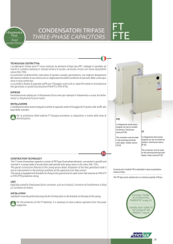
rifasamento
fisso
fixed
power-factor
CONDENSATORI TRIFASE
THREE-PHASE CAPACITORS
UTF
TECNOLOGIA COSTRUTTIVA
I condensatori modulari trifase serie UTF sono costituiti da tre elementi monofase tipo PRM, collegati a triangolo ed inseriti in custodia realizzata in robusta lamiera di acciaio, verniciata a fuoco con
resine epossidiche colore RAL 7035.
Le particolari caratteristiche costruttive di questa custodia garantiscono una migliore dissipazione
del calore prodotto al suo interno ed un miglioramento delle condizioni di esercizio delle unità
capacitive in esse contenute.
La custodia è dotata di apposite staffe per il fissaggio a terra ed un coperchio esterno di protezione
terminali in nylon rinforzato vetro che garantisce un grado di protezione IP30.
Grazie alla sua struttura modulare è possibile l’assemblaggio elettrico e meccanico in modo facile
e funzionale.
IMPIEGHI
Particolarmente adatte grazie alla loro modularità per il rifasamento fisso di motori e trasformatori.
Utilizzando gli speciali agganci posti sulla base della custodia e le barrette in parallelo, è
possibile ottenere potenze desiderate senza superare la corrente totale di 75 A.
INSTALLAZIONE
L’installazione deve essere eseguita tramite le apposite asole di fissaggio 8x10 poste sulle staffe
alla base della custodia.
Nel caso di realizzazione di batterie con due o più unità verificare il corretto serraggio delle apposte connessioni dei terminali di alimentazione e di terra.
CONSTRUCTION TECHNOLOGY
The UTF series, three-phase modular capacitors consist of three PRM-type single-phase elements, delta
connected and inserted in a casing made of sturdy sheet steel painted with epoxy resins in the colour
RAL 7035.
The special construction features of this casing ensure better dissipation of the heat generated inside it
and an improvement in the working conditions of the capacitive units they contain.
The casing is equipped with brackets for fixing to the ground and an outer cover to protect the terminals made of fibreglass-reinforced nylon that ensures an IP30 protection rating.
Thanks to its modular structure, its electrical and mechanical assembly is easy and functional.
USES
Especially suited, thanks to its modularity, for fixed power factor correction of motors and transformers.
I prodotti descritti sono suscettibili in qualsiasi momento di evoluzioni o di
modifiche. Le descrizioni ed i dati a catalogo non possono pertanto avere
alcun valore contrattuale.
Technical data and descriptions in the pubblication are accurate, to the
best of our knoweledge, but no liabilities for errors, omissions or contingencies arising therefrom are accepted.
consultare “GUIDA
ALLA SCELTA DEL
PRODOTTO” a pag. 20
carefully check “GUIDE TO
THE CHOISE OF THE
PRODUCT” pag 20
Using the special hooks on the base of the casing and the parallel bars, it is possible to get the
required power without exceeding the total current of 75 A.
INSTALLATION
Installation must be performed using the 8x10 fixing slots on the brackets at the base of the casing.
If making banks with two or more units, check the connections of the power supply and earth terminals
are tightened properly.
27
CONDENSATORI TRIFASE
THREE-PHASE CAPACITORS
UTF
CODICE
REFERENCE
Coperchio per protezione (IP 40)
Protection cover (IP 40)
H - 50 ± 2
12
H ±2
Connessione
di terra (M6)
Earth connection
(M6)
UTF.2325
UTF.2350
UTF.4025
UTF.4050
UTF.4075
UTF.4100
UTF.4125
UTF.4105
UTF.4110
UTF.4112
UTF.4405
UTF.4410
UTF.4412
UTF.4415
UTF.4805
UTF.4810
UTF.4812
UTF.4815
UTF.5205
UTF.5210
UTF.5215
kvar
V
A
µF
2.5
5.0
2.5
5.0
7.5
10.0
12.5
5.0
10.0
12.5
5.0
10.0
12.5
15.0
5.0
10.0
12.5
15.0
5.0
10.0
15.0
230
230
400
400
400
400
400
415
415
415
440
440
440
440
480
480
480
480
525
525
525
6.28
12.56
3.60
7.20
10.80
14.40
18.00
6.96
13.93
17.41
6.56
13.13
16.42
19.70
6.02
12.04
15.05
18.06
5.51
11.01
15.52
3 x 50.2
3 x 100.3
3 x 16.6
3 x 33.3
3 x 50.0
3 x 66.7
3 x 83.3
3 x 30.8
3 x 61.6
3 x 77.0
3 x 27.3
3 x 54.7
3 x 68.7
3 x 82.0
3 x 23.0
3 x 46.0
3 x 57.6
3 x 69.1
3 x 19.2
3 x 39.5
3 x 57.7
DIMENSIONI / DIMENSIONS
W (mm)
Ø (mm)
H (mm)
CONFEZIONE PZ.
PACKING PCS
250
250
250
250
250
250
250
250
250
250
250
250
250
250
250
250
250
250
250
250
250
81
81
81
81
81
81
81
81
81
81
81
81
81
81
81
81
81
81
81
81
81
284
284
284
284
284
284
284
284
284
284
284
284
284
284
284
284
284
284
284
284
284
5
5
5
5
5
5
5
5
5
5
5
5
5
5
5
5
5
5
5
5
5
Kit per collegamento cod. SL KITUTF / Kit for assembly cod. SL KITUTF
L ± 0.5
L-5 ± 0.5
10
CARATTERISTICHE TECNICHE
8
L+9 ± 0.5
Terminali M8
Terminals M8
TECHNICAL PARTICULARS
Tensione nominale (Un)
W-30 ± 1
W±1
Esempio di assemblaggio batteria
Example of battery assembly
Frequenza nominale
230 - 400 - 415 - 440 - 480 - 525 V
Tolleranza sulla capacità
Tolerance on capacitance
Classe temperatura
- 25 ° C / + 55 ° C
Perdite dielettriche
≤ 0,2 W/kvar
Dielectric losses
≤ 0,5 W/kvar
Total losses (at the terminals)
Perdite totali (ai morsetti)
Livello di isolamento
Insulation level
1,3 In
Prova di Tensione tra i terminali
Max. permitted current
≤ 100 In
Maximum peak value of the current transient
2,15 Un per 2’’ - 2.15 Un for 2’’
Prova di Tensione tra i terminali e la cassa
Terminali
3 KV per 10”
Voltage test between the terminals
Voltage test between the terminals and contanier
3 viti M8 / 3 M8 screws
Terminals
Esterne (riduzione a 75 V entro 3 min)
External (reduction to 75 V within 3 min)
Resistenze di Scarica
Servizio
Discharge resistors
Continuo - Continuous
Installazione
Raffreddamento
Temperature class
3/15 kV Ue ≤ 660 Vac
Massimo valore di cresta del transitorio di corrente
Service
Interno - Indoor
Installation
Aria Naturale - Natural
Umidità max accettabile
Cooling
80%
Altitudine
Max permissible humidity
≤ 2000 (m s.l.m. - m a.s.l.)
Altitude
Grado di protezione
IP 30 con coperchio di protezione - IP 30 with protection cover
Durata vita prevista
>100.000 h (classe D) - >130.000 h (classe C)
Expected life
Fissaggio
Tramite staffe asolate 8x10 mm per vite M8
With slotted brackets 8x10mm for M8 screws
Fixing
Norme di riferimento
CEI EN 60831-1/2, IEC 60831-1/2
Tensioni di manovra
Max 5000 operazioni di manovra all’anno in accordo con norme IEC 60831-1
Max 5000 switchings per year according to IEC 60831-1
Altre caratteristiche realizzabili su richiesta.
28
Rated frequency
- 5% ÷ + 10%
Massima corrente ammessa
Connessione di terra
Earth connection
Rated voltage (Un)
50 Hz (60 Hz a richiesta) - 50 Hz (60 Hz on request)
Degree of protection
Reference standards
Number of switching operation
Other characteristics can be made on request.
© Copyright 2026 Paperzz