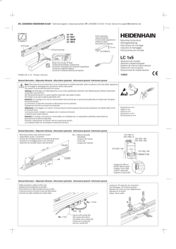
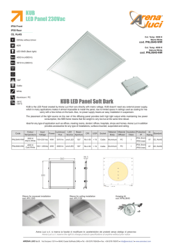
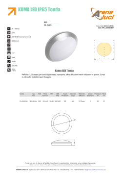
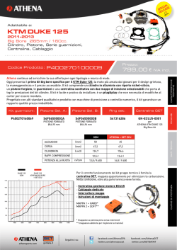
Information
Power Parts
76014937044
12. 2012
3.211.904
*3211904*
www.ktm.com
DEUTSCH
Danke, dass Sie sich für KTM Power Parts entschlossen haben.
Alle unsere Produkte wurden nach den höchsten Standards entwickelt und gefertigt, unter Verwendung der besten verfügbaren
Materialien.
KTM Power Parts sind rennerprobt und gewährleisten ultimative Performance.
KTM KANN NICHT VERANTWORTLICH GEMACHT WERDEN FÜR FALSCHE MONTAGE ODER VERWENDUNG DIESES PRODUKTS. Bitte
befolgen Sie die Montageanleitung. Fachmännische Beratung und korrekte Installation der KTM PowerParts durch einen autorisierten
KTM Händler sind unerlässlich, um das Optimum an Sicherheit und Funktionalität zu gewährleisten.
Danke.
ENGLISH
2
Thank you for choosing KTM Power Parts!
All of our products are designed and built to the highest standards using the finest materials available.
KTM Power Parts are race proven to offer the ultimate in performance.
KTM WILL NOT BE HELD LIABLE FOR IMPROPER INSTALLATION OR USE OF THIS PRODUCT. Please follow all instructions provided.
Professional advice and proper installation of the KTM PowerParts by an authorized KTM dealer are essential to provide maximum
safety and functions.
Thank you.
ITALIANO
2
Grazie per aver deciso di acquistare un prodotto KTM Power Parts.
Tutti i nostri prodotti sono stati sviluppati e realizzati secondo i massimi standard e con l'impiego dei migliori materiali disponibili.
Le KTM Power Parts sono collaudate nelle competizioni ed assicurano altissime prestazioni.
KTM NON PUÒ ESSERE RESA RESPONSABILE PER UN MONTAGGIO O USO IMPROPRIO DI QUESTO PRODOTTO. Per favore osservate le
istruzioni nel manuale d'uso. Al fine di garantire la massima sicurezza e il corretto funzionamento, è indispensabile farsi consigliare
da persone esperte e competenti e far eseguire l'installazione delle KTM PowerPart presso i concessionari KTM autorizzati.
Grazie.
FRANCAIS
2
Nous vous remercions d'avoir choisi KTM Power Parts.
Tous nos produits ont été développés et réalisés selon les plus hauts standards et en utilisant les meilleurs matériaux disponibles.
Les Power Parts de KTM ont fait leurs preuves en compétition et garantissent les meilleures performances.
LA RESPONSABILITÉ DE KTM NE SAURAIT ÊTRE ENGAGÉE EN CAS D'ERREUR DANS LE MONTAGE OU L'UTILISATION DE CE PRODUIT.
Il convient de respecter les instructions de montage.
Le conseil spécialisé et l'installation dans les règles de l'art des PowerParts KTM par un concessionnaire KTM agréé sont
indispensables pour assurer un maximum de sécurité et de fonctionnalité.
Merci.
ESPANOL
2
2
Gracias por haberse decidido por el Power Parts KTM.
Todos nuestros productos han sido desarrollados y producidos según los estándares más altos utilizando los mejores materiales
disponibles.
Las KTM Power Parts están probadas en competencia y garantizan un óptimo rendimiento.
NO SE PUEDE HACER RESPONSABLE A LA KTM POR UN MONTAJE O UN USO INCORRECTO DE ESTE PRODUCTO.
Le rogamos seguir las instrucciones para el montaje.
A fin de garantizar la máxima seguridad y un funcionamiento correcto es imprescindible acudir a un concesionario autorizado de KTM
para obtener el mejor asesoramiento técnico e instalar correctamente las KTM PowerParts.
Gracias.
4
1
2
1
2x
2x
1x
1x
LED-Blinker vorne rechts / hinten links (1)
LED-Blinker vorne links / hinten rechts (2)
Adapterkabel (3)
Blinkerrelais (4)
76014026000
76014025000
76011025000
76011030000
2
3
3
Während der Montage muss die Zündung ausgeschaltet sein.
HINWEIS:
Auf der Unterseite der Blinker ist ein Aufkleber angebracht. Dieser gibt
Auskunft über die Montageposition.
FRONT LH:
FRONT RH:
REAR LH:
REAR RH:
6
5
Montage
Montage
Montage
Montage
vorne links
vorne rechts
hinten links
hinten rechts
Montage
- Scheinwerfermaske (5) demontieren (siehe Bedienungsanleitung).
- Original-Blinker (6) vorne auf beiden Seiten demontieren.
- LED-Blinker vorne auf beiden Seiten montieren.
- Original-Blinkerrelais (7) mit Blech (8) demontieren.
- Stecker des Original-Blinkerrelais (9) abziehen.
7
9
8
DEUTSCH
Lieferumfang:
DEUTSCH
- Blech (8) vom Original-Blinkerrelais (7) abziehen und am Blinkerrelais (4)
anbringen.
4
7
8
4
12
- Stecker (13) des Adapterkabels (3) (Lieferumfang) am Blinkerrelais (4)
(Lieferumfang) anschließen.
11
3
9
- Stecker des Original-Blinkerrelais (9) mit Stecker (10) des Adapterkabels
verbinden.
- Flachkontaktstecker (11) mit der Masse (braun) von ACC1 (12) verbinden.
10
13
4
- Blinkerrelais (4) (Lieferumfang) mit Unterlegscheibe (14) montieren.
4
- Scheinwerfer und LED-Blinker anstecken.
14
- Scheinwerfermaske montieren (siehe Bedienungsanleitung).
HINWEIS:
Zur Demontage der Blinker muss je nach Modell der Kennzeichenträger
demontiert werden.
- Original-Blinker hinten demontieren und abstecken.
- LED-Blinker hinten montieren und anstecken.
Endmontage
Nach der Montage muss eine Funktionskontrolle der gesamten Lichtanlage
durchgeführt werden.
Scope of supply:
4
1
2
1
2x
2x
1x
1x
LED turn signals, front right/rear left (1)
LED turn signals, front left/rear right (2)
adapter cable (3)
turn signal relay (4)
76014026000
76014025000
76011025000
76011030000
2
The ignition must be switched off during installation.
NOTE:
A label is found on the underside of the turn signal. It provides information
on the installation position.
FRONT LH:
FRONT RH:
REAR LH:
REAR RH:
Installation
Installation
Installation
Installation
at
at
at
at
front left
front right
rear left
rear right
ENGLISH
3
5
6
5
Assembly
- Remove the headlight mask (5) (see the Owner’s Manual).
- Remove the original turn signals (6) at the front on both sides.
- Mount the LED turn signals at the front on both sides.
- Remove the original turn signal relay (7) with the plate (8).
- Detach the connector of the original turn signal relay (9).
7
9
8
- Detach the plate (8) from the original turn signal relay (7) and attach it to
the new turn signal relay (4).
4
7
8
ENGLISH
12
- Connect the connector (13) of the adapter cable (3) (included) to the turn
signal relay (4) (included).
11
3
9
- Connect the connector of the original turn signal relay (9) with the connector (10) of the adapter cable.
- Connect the flat pin connector (11) with the ground wire (brown) of ACC1
(12).
10
13
4
6
- Mount the turn signal relay (4) (included) with the washer (14).
4
- Connect the headlights and LED turn signals.
14
- Mount the headlight mask (see the Owner’s Manual).
NOTE:
To remove the turn signals, the license plate holder may have to be first,
depending on the model.
- Remove the original turn signals at the rear and disconnect them.
- Mount the LED turn signals at the rear and connect them.
Final steps
After installation, the entire lighting system must be checked for proper functioning.
Volume della fornitura:
4
1
2
1
N. 2 indicatori di direzione a LED lato anteriore destro / posteriore sinistro (1)
76014026000
N. 2 indicatori di direzione a LED lato anteriore sinistro / posteriore destro (2)
76014025000
N. 1 cavo adattatore (3)
76011025000
N. 1 relè indicatori (4)
76011030000
2
3
Durante il montaggio, l’accensione deve essere disinserita.
NOTA:
Sul lato inferiore degli indicatori di direzione è applicato un adesivo con indicata la posizione di montaggio.
FRONT LH:
FRONT RH:
REAR LH:
REAR RH:
5
in
in
in
in
posizione
posizione
posizione
posizione
anteriore sinistra
anteriore destra
posteriore sinistra
posteriore destra
Montaggio
- Smontare la mascherina portafaro (5) (vedere il manuale d’uso).
- Smontare gli indicatori di direzione anteriori originali (6) su entrambi i lati.
ITALIANO
6
montaggio
montaggio
montaggio
montaggio
7
- Montare su entrambi i lati gli indicatori di direzione anteriori a LED.
- Smontare il relè indicatori originale (7) con la piastrina (8).
- Staccare il connettore del relè indicatori originale (9).
7
9
8
- Staccare la piastrina (8) dal relè indicatori originale (7) e applicarla sul
relè indicatori (4).
4
7
8
12
- Collegare il connettore (13) del cavo adattatore (3) (in dotazione) al relè
indicatori (4) (in dotazione).
11
3
9
- Collegare il connettore del relè indicatori originale (9) con il connettore
(10) del cavo adattatore.
- Collegare il connettore a contatto piatto (11) con la massa (marrone) di
ACC1 (12).
10
13
4
- Montare il relè indicatori (4) (in dotazione) con la rondella (14).
ITALIANO
4
- Collegare il faro e gli indicatori di direzione a LED.
14
- Montare la mascherina portafaro (vedere il manuale d’uso).
8
NOTA:
Per lo smontaggio degli indicatori di direzione, a seconda del modello si dovrà
smontare il portatarga.
- Smontare e scollegare gli indicatori di direzione posteriori originali.
- Montare e collegare gli indicatori di direzione posteriori a LED.
Montaggio finale
Terminato il montaggio eseguire un controllo funzionale dell’impianto luci
completo.
Contenu de la livraison :
4
1
2
1
2x
2x
1x
1x
Clignotant à LED avant droit / arri re gauche (1)
Clignotant à LED avant gauche / arrière droit (2
Câble d’adaptateur (3)
Relais de clignotants (4)
76014026000
76014025000
76011025000
76011030000
2
3
Pendant le montage, l’allumage doit être coupé.
REMARQUE :
Un autocollant est collé sous le clignotant. Il illustre la position de montage.
FRONT LH:
FRONT RH:
REAR LH:
REAR RH:
6
5
Montage
Montage
Montage
Montage
avant gauche
avant droit
arrière gauche
arrière droit
Montage
- Démonter la plaque-phare (5) (voir le manuel d’utilisation).
- Démonter les clignotants d’origine (6) à l’avant, des deux côtés.
FRANCAIS
- Monter les clignotants à LED à l’avant, des deux côtés.
9
- Déposer le relais de clignotants d’origine (7) avec la plaque (8).
- Retirer le connecteur du relais de clignotants d’origine (9).
7
9
8
- Retirer la plaque (8) du relais de clignotants d’origine (7) et le monter sur
le relais de clignotants (4).
4
7
8
12
- Raccorder le connecteur (13) du câble d’adaptateur (3) (contenu de la livraison) au relais de clignotants (4) (contenu de la livraison).
11
3
9
- Brancher le connecteur du relais de clignotants d’origine (9) avec le connecteur (10) du câble d’adaptateur.
- Connecter le connecteur à contact plat (11) avec la masse (marron) de
ACC1 (12).
10
13
4
- Monter le relais de clignotants (4) (contenu de la livraison) avec la rondelle (14).
4
14
- Brancher le phare et les clignotants à LED.
- Mettre la plaque-phare en place (voir manuel d’utilisation).
FRANCAIS
REMARQUE :
Pour le démontage des clignotants, selon le modèle, il peut s’avérer nécessaire de démonter d’abord le support de plaque.
- Démonter et débrancher le clignotant arrière d’origine.
- Monter et brancher le clignotant arrière à LED.
10
Montage final
A l’issue du montage, effectuer un contrôle du fonctionnement de l’ensemble du circuit d’éclairage.
Volumen de suministro:
4
1
2
1
2 intermitentes LED: delantero derecho / trasero izquierdo (1)
76014026000
2 intermitentes LED: delantero izquierdo / trasero derecho (2)
76014025000
1 cable adaptador (3)
76011025000
1 relé del intermitente (4)
76011030000
2
3
El encendido debe permanecer desconectado durante el montaje.
ADVERTENCIA:
En la parte inferior del intermitente hay un adhesivo con información sobre
la posición de montaje.
FRONT LH:
FRONT RH:
REAR LH:
REAR RH:
6
5
montaje
montaje
montaje
montaje
delante a la izquierda
delante a la derecha
detrás a la izquierda
detrás a la derecha
Montaje
- Desmontar la cubierta del faro (5) (véase el manual de instrucciones).
- Desmontar los intermitentes delanteros originales (6) en ambos lados.
- Montar los intermitentes LED delanteros en ambos lados.
- Quitar el conector del relé del intermitente original (9).
7
9
8
ESPANOL
- Desmontar el relé del intermitente original (7) con la chapa (8).
11
- Quitar la chapa (8) del relé del intermitente original (7) y colocarla en el
relé del intermitente (4).
4
7
8
12
- Conectar el conector (13) del cable adaptador (3) (volumen de suministro)
al relé del intermitente (4) (volumen de suministro).
11
3
9
- Conectar el conector del relé del intermitente original (9) con el conector
(10) del cable adaptador.
- Conectar el conector plano (11) a la masa (marrón) de ACC1 (12).
10
13
4
- Montar el relé del intermitente (4) (volumen de suministro) en la arandela
(14).
4
14
- Conectar el faro y el intermitente LED.
- Montar la cubierta del faro (véase el manual de instrucciones).
ADVERTENCIA:
Dependiendo del modelo, para desmontar los intermitentes también debe
desmontarse el soporte de la placa de matrícula.
- Desmontar y desenchufar el intermitente trasero original.
- Montar y conectar el intermitente LED trasero.
Montaje final
ESPANOL
12
Una vez finalizado el montaje, debe realizarse un control de funcionamiento
de todo el equipo de luces.
© Copyright 2026 Paperzz