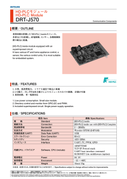
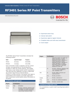
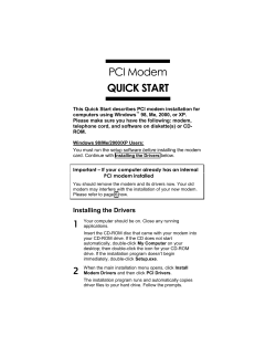
BITxxRML RF Transceiver Module (Radio Modem) Application o Ultra low power wireless Transceiver o 433/868/915 and 2400 Mhz ISM/SRD band systems o Consumer Electronics o Wireless audio o Alarm and security systems o Home and building automation o Wireless sensor networks o Industrial monitoring and control o Low power Telemetry Product Description The BITxxRML is a very low cost transceiver module designed for very low power wireless applications. This module is intended for ISM (Industrial, Scientific and Medical) and SRD (Short Range Device) frequency band at 433, 868/915 and 2400 Mhz., but can easily be programmed for operation at other frequencies: BIT04RML 400 – 464 Mhz BIT08RML 800 – 928 Mhz BIT24RML 2400 – 2483 Mhz. It is designed to realize RF solutions easy to use providing a reliable data transfer among remote equipments. The module can operate with a UART (up to 76.8 kbps) connected host or as a stand alone complete RF module. BITxxRM has up to 11 I/O pins (2 analog) completely programmable from a remote controller; so it can act as an RF I/O expander (battery operated sensor solution). It’s fully programmable in a very small package: only 15 x 28 mm ready for SMT assembly. Key Features o Small size (15 x 28 mm package, 17 pins). o Frequency bands: • BIT04RML 430 – 434 MHz • BIT08RML 866 – 870 Mhz 905 – 925 MHz BIT24RML 2410 – 2470 Mhz. o High sensitivity (-110 dbm at 1.2 kpbs, 1% PER at 433 and 868 Mhz and –106 dbm at 2.4 kbps, 1% PER at 2,4 Ghz). Bit is Italian Technology S.r.l. o Programmable output power up to + 10 dBm for BIT04RML/BIT08RML and +1 dBm for BIT24RML. o Low current consumption (18,4 mA in RX,1,2 kbps,433 Mhz and 16,3 mA in RX, 250 kbps,input 30 dB above sensitivity limit) o Operating Voltage : BITxxRML 1.8 to 3.6 V. o UART Data rate up to 38.4 kBaud o Modulation: GFSK e MSK. BITxxRMx Preliminary Datasheet (Rev. 2.2 10-12-2014) Pagina 1 di 16 BITxxRML Features (continued from front page) o Fully customizable upon request. o Programmable data rate up to 250 kbps o Ideal for multi-channel operation. o Forwad Error Correction with interleaving. o Excellent receiver selectivity and blocking performance. o BIT04RML/BIT08RML suited for system compliant with EN 300 220 (Europe) and FCC CFR Part 15 (US). o BIT24RML suited for system compliant with EN 300 328 and EN 300 440 class 2 (Europe), CFR47 Part 15 (US) and ARIB STD-T66 (Japan). 1. Pin-Out The radio modem is equipped with a certain number of pin available for the host application. Some are already used (see next sections); for the others it is possible to agree a product customization. PIN # PIN NAME P01 (1) RC0/RTS/T1OSO/T13CKI P02 (1) RC1/T1OSI P03 TX/RC6 TX RX/RC7 RX CONFIG /WAKE-UP CONFIG/WAKE-UP P04 P05 Pin Type O I I O I O I I O I I Buffer Type ST ST ST ST CMOS Description Digital Output. Digital Input. Request to send (active low) Timer1 oscillator output. Timer1/Timer3 external clock input. Digital Output. Digital Input. Timer1 oscillator input. TX EUSART asynchronous trasmit. RX EUSART asynchronous receive. CONFIG/WAKE-UP (default config: 0) TTL/ST Enter in configuration mode (active-low) Wake-up from sleep (active high) P06 (1) RB2/INT2/AN8 O I I I TTL ST Analog Digital Output. Digital Input. Interrupt-on-change pin Analog Input 8. P07 (1) RB3/AN9/CCP2 O I O I I/O TTL Analog ST Digital Output. Digital Input. PWM at 31,25 KHz Analog Input 9. Capture 2 input/Compare 2 output/PWM 2 output. Bit is Italian Technology S.r.l. BITxxRMx Preliminary Datasheet (Rev. 2.2 10-12-2014) Pagina 2 di 16 BITxxRML PIN # P08 P09 P10 P18 P19 P20 P26 P27 P29 (1) P30 (1) PIN NAME MCLR/Vpp MCLR Vpp Vss Vdd AVss1 ANT AVss2 PA_EN LNA_EN/RB7/KBI3/PGD RB7 RB7 LNA_EN KBI3 PGD RA7/OSC1/CLKIN RA6/OSC2/CLKOUT Pin Type Buffer Type I Power ST - Power Power Power RF I/O Power - O I ST O I/O ST O I O TTL - O - O I I TTL ST I CMOS Description MCLR/Vpp Master Clear(Reset) input.This pin is activelow Programming voltage input Ground connection 2.7V – 5.5V power supply connection Antenna Ground RF input/output to Antenna Antenna Ground PA_EN External PA enable (active high) In-Circuit debugger and ICSP Programming clock pin LNA_EN External LNA enable (active high) In-Circuit debugger and ICSP Programming data pin Digital Outut. Digital Input. Oscillator crystal input or external clock source input. ST buffer when configured in RC mode; analog otherwise. External clock source input. Always associated with pin function OSC1. Digital Output. Digital Input. Oscillator crystal output. Connects to crystal or resonator in Crystal Oscillator mode. In RC mode, OSC2 pin outputs CLKO which has ¼ the frequency of OSC1 and denotes the instruction cycle rate. Note (1): P01, P02, P06, P07, P29 and P30 are pins not used in the default firmware, and they are configurated in low output Table 1.1: Pin Description Bit is Italian Technology S.r.l. BITxxRMx Preliminary Datasheet (Rev. 2.2 10-12-2014) Pagina 3 di 16 BITxxRML 2. Absolute Maximum Ratings Parameter Supply Voltage, VDD Voltage on any pin Input RF level Storage temperature range Min. -3 -0.3 Max. 3.9 VDD+0.3 10 85 -40 Units V V dBm °C Remarks BITxxRML version 3. Operating Conditions and Specifications Parameter Min. RF Frequency Range Typ. 433.32 433.92 864.00 868.30 2.410 2.440 -30 Operation ambient temperature Supply voltage 1.8 Current Consumption Sensitivity - Max. Units Remarks 434.52 869.90 2.470 +85 MHz MHz GHz °C 04 version 08 version 24 version 3.6 V BITxxRML version 5 30 uA mA 20 -109 -93 dBm dBm Sleep mode Transmit mode @ max output power Receive mode @ 1.2 kbps @ 1.2 kbps @ 125 kbps 4. Available Versions The product is available in three different versions that can be identified and ordered as follows: BIT08RML Operating in the frequency band range between 864.000-869.900 MHz and 905.000-925.000 MHz. BIT04RML Operating in the frequency band range between 433.320-434.520 MHz . BIT24RML Operating in the frequency band range between 2.410-2.470 GHz. 4.1. Product customization The product is fully customizable upon request; it is possible to customize operating frequencies, data-rate, pin Bit is Italian Technology S.r.l. use, functions, etc. Please contact the Distributors closest to you for further information. BITxxRMx Preliminary Datasheet (Rev. 2.2 10-12-2014) Pagina 4 di 16 BITxxRML 5. Data Transmission When not set in configuration mode (see below), the radio modem receives the characters on the RX line that must be sent in 8 bit data mode, 1 bit stop, no parity and baud rate equal to the one set in configuration (19.200 kbps from manufacturer); when the number of characters received and not transmitted by radio reaches the number set as package length, they are sent; if between one character and the other there is a time interval equal or higher than Timeout setting, the radio modem sends out the characters all the same, even if the quantity he got was not equal to the package length. The modem has got an UART reception buffer with the length of 256 characters; when the buffer is full and it is therefore no longer possible to receive other UART characters, the CTS pin go high, showing that it can no longer receive further characters until it is able to send them by radio, emptying the UART reception buffer. RX (from host) CTS (from BITRM) Buffer ready Buffer full Buffer ready Buffer full 6. Configuration Controls The modem is equipped with a complete set of commands to control and program all the modem’s functionalities. Local Mode: All commands are accessible with the UART interface. The UART interface is a standard type with 8 bit of data, 1 bit of stop, no parity and settable Baud Rate. It is possible to change the configuration in any moment. In that case one has to operate in the following way: Bring the CONFIG pin to GND or send ESCAPE SEQUENCE; the radio modem replies with the form feed character <FF(Hex=0C)> <CR><LF> send the command: AT+cmd=val<CR> cmd is one of the commands mentioned in the next table; val is always formed by 3 characters Bit is Italian Technology S.r.l. with values that depend on the performed command; as an alternative the 3 characters ??? (Hex=3F) bring back to the current configuration value <CR> is the carriage return character (Hex=0D). The modem reply messages always start and end with <CR><LF> (Hex=0D0A),except Ok and ERR where the modem reply with <CR><LF> Ok or ERR <LF><CR> ; we will skip them to be shorter. If the command has been correctly performed the modem will reply with Ok; otherwise it will reply with ERR. At the end you have to send the command AT+CF=SET<CR>. Wait until the radio modem gives back the form feed character <FF> (Hex=0C) and realease high the CONFIG. Now new configuration is active BITxxRMx Preliminary Datasheet (Rev. 2.2 10-12-2014) Pagina 5 di 16 BITxxRML Remote Mode: It is also possible to program a radio modem in remote mode via RF link. Just append the “RC” (Remote Command) suffix after “+” in the command. Example: AT+RCPL=003 AT+RCCF=SET Set remote device packet length = 3. The next table shows the command set to be used in configuration. The use of RF frequencies, maximum allowed RF power and duty-cycles are limited by national regulations. The BIT04RM and BIT08RM is complying with the applicable directives within the European Union when used within these limitations (see Appendix A: CEPT ERC RECOMMENDATION 70-03). Comm Syntax Description (see 6.1-6.10) Possible Values val Sets the baud rate for the 000, , 006 UART interface Sets the character reception 000, , 255 timeout after which it will send out the RF package in any way Sets the length of the RF 001, , 050 package Sets the output power 000, , 008 Sets one of the five RF 000, , 009 configurations to be used Sets the RF channel on See 6.6 which to operate Sets the Net Address on 000, , 255 which to filter the package Sets My Address on which 000, , 255 to filter the package Sets the Destination 000, , 255 Address to send the package Sets the TX criteria on CCA 000, , 003 (Clear Channel Assessment) Sets Automatic Frequency SET, RST Compensation (AFC) Return Firmware Version ??? Return RSSI and Link ??? Quality Indicator Puts the radio modem in 000, , 255 SLEEP mode BR AT+[RC]BR=val<CR> TO AT+[RC]TO=val<CR> PL AT+[RC]PL=val<CR> PA RF AT+[RC]PA=val<CR> AT+[RC]RF=val<CR> CH AT+[RC]CH=val<CR> NA AT+[RC]NA=val<CR> MA AT+[RC]MA=val<CR> DA AT+[RC]DA=val<CR> CS AT+[RC]CS=val<CR> EA AT+[RC]EA=val<CR> FV LQ AT+[RC]FV=val<CR> AT+[RC]LQ=val<CR> PD AT+[RC]PD=val<CR> CF AT+[RC]CF=val<CR> Return or Saves the actual SET, RST configuration Table 6.1: Configuration Commands Bit is Italian Technology S.r.l. BITxxRMx Preliminary Datasheet (Rev. 2.2 10-12-2014) Factory Default Value 003 000 001 See 6.4 000 See 6.6 211 000 000 000 - Pagina 6 di 16 BITxxRML 6.1. ESCAPE SEQUENCE The Serial Port can be in two different modes AT mode and data mode. It is possible enter in AT mode by sending an escape sequence. The escape sequence consists of three consecutive forward plus characters '+'. The following criteria must be met for the Serial Port Adapter to interpret the sequence as a valid escape sequence: Before the escape sequence there must be silence for 1 second. After the escape sequence there must be silence for 1 second and max 75ms the silence between two + charater . If the module enter in AT Mode with escape sequence use the "AT+CF " command to move from AT mode to data mode, 6.2. BR: UART Baud Rate The UART baud rate can be set to 5 different values; the character reception TimeOut is linked to this BR 0 1 2 3 (default) 4 5 6 setting (see section 6.2). The possible settings are shown in next table. UART Baud Rate (bps) 2400 4800 9600 19200 38400 57600 76800 Table 6.2: UART Baud Rate 6.3. TO: Timeout With timeout it is meant the inactivity time on the serial in input to the radio modem, after that the acquired characters are sent out by RF anyway without waiting for the package length to be filled; it is expressed as multiple of the bit length To val Tb ; setting “val” equal to 000 (default), the timeout is disabled. Tb 10 6 s BRbps 6.4. PL: Package Length The package length is the number of characters that the radio modem waits to receive from the UART before packaging them in the frame and send them in the air. Bit is Italian Technology S.r.l. If the time that passes between one character and the next if higher than Timeout (see section 6.2), then the radio modem sends out the received characters in any way. BITxxRMx Preliminary Datasheet (Rev. 2.2 10-12-2014) Pagina 7 di 16 BITxxRML 6.5. PA: Output Power Is the settable output power. The listed power consumption refers only to the radio side. To this typically have to be added 3mA for the PA 433 MHz Output Power (dbm) 0 1 2 3 4 5 6 7 8 microcontroller with only the EUSART active. Following table shows the possible settings. 868 MHz 915 MHz Current consumption , typ. [mA] Output Power (dbm) Current consumption , typ. [mA] Outpu t Power (dbm) Current consumption , typ. [mA] 11.5 12.0 12.7 14.0 13.7 15.5 19.0 24.2 28.9 -30 -20 -15 -10 -5 +0 +5 +7(def) +10 11.9 12.4 13.0 14.5 14.1 16.9 20.0 25.8 30.7 -30 -20 -15 -10 -5 +0 +5 +7 +10 11.8 12.3 13.0 14.0 13.9 16.7 19.3 25.8 32.3 -30 -20 -15 -10 -5 +0 +5 +7 +10(def) 2.4 GHz Output Power (dbm) Current consumption, typ. [mA] -30 -26 -20 -16 -12 -8 -4 0 +1.5(def) 9.9 10.2 10.1 10.8 11.1 14.1 16.2 21.2 21.5 Table 6.3: TX Output Power 6.6. RF: RF Configurations All five RF configurations have following characteristics in common: 8 byte header (0xAA) 2 byte SYNC WORD (0xD391) Network address (settable with command NA) Config Kbps CRC Error correction method. Following table shows the peculiar characteristics of each configuration: RX filter Modulation Typical Sensitivity (dbm) BIT04RM BIT08RM BIT24RM bandwidth 433 MHz 868 MHz 915 MHz 0 1.2 58 KHz GFSK -110 -110 1 4.8 100 KHz GFSK -107 -107 2 19.2 100 KHz GFSK -102 -103 3 38.4 230 KHz GFSK -99 -99 4 125.0 540 KHz MSK -93 -93 5 1.2 58 KHz GFSK -110 6 4.8 100 KHz GFSK -107 7 19.2 100 KHz GFSK -103 8 38.4 230 KHz GFSK -99 9 125.0 540 KHz MSK -93 10 10* 58 KHz GFSK -110 *must enable AFC on slave Table 6.4: Characteristics of the RF configurations Bit is Italian Technology S.r.l. BITxxRMx Preliminary Datasheet (Rev. 2.2 10-12-2014) 2.4 GHz -104 -99 -97 -95 -89 - Pagina 8 di 16 BITxxRML 6.7. CH: RF Channel 6.7.1. Versions 04 and 08 (868 MHz) 13 channels placed at a distance of 100 KHz one from another are available for the versions 433 and 868. A particular attention goes to the use of the various available channels, as they are strictly linked to the adopted RF configuration (channel length, baud rate, etc.) in order to respect the approval specifications. Channel Central Frequency(MHz) 04 version 08 version 0 433.32 863.50 1 433.42 863.75 2 433.52 864.00 3 433.62 864.25 4 433.72 864.50 5 433.82 864.75 6 433.92 868.20 7 434.02 868.30(default) 8 434.12 868.40 9 434.22 (default) 868.85 10 434.32 868.95 11 434.42 869.05 12 434.52 869.50 Table 6.5: Available channels for 04 and 08 versions 6.6.2Version 08 (915 MHz) In the 915 Mhz version there are 50 channels available placed at a distance of 400 Khz, it is possible to achieve the carrier frequency f c with following formula: f c f cm val 0,4Mhz fcm = minimum fc equal to 905 Mhz val = set value from 0 to 50 6.6.3Version 24 In the 2.4 Ghz version there are 256 channels available placed at a distance of 250 Khz, it is possible to achieve the carrier frequency f c with following formula: Bit is Italian Technology S.r.l. f c f cm val 0,25Mhz fcm = minimum fc equal to 2410 Mhz val = set value from 0 to 255 BITxxRMx Preliminary Datasheet (Rev. 2.2 10-12-2014) Pagina 9 di 16 BITxxRML 6.8. Addressing The module allows addressed packet transmissions and broadcast transmissions. Each module has a Network Address (one byte) and its own My Address (one byte). The Network Address and My Address can be programmed for each module using the configuration interface (Remote Mode or Local Mode). The use of addressing can be enabled writing My Address and Destination Address with a number different of 000. Each module also has a Destination Address. This address will be added to the data packet If value is different of 000. All Node in one system should have the same Network Address, and each node should be set to a different My Address. 6.8.1. NA: Network Address The network address helps to filter the RF packets with its own network address; briefly, all radio modems with 6.8.2. MA: My Address My address filter all the RF packets that don’t have in the destination address field the same value of MA. 6.8.3. the same network address are able to communicate among themselves. MA=000 disable function MA = 255 receive all message DA: Destination Address The Destination Address value is added to the RF packets. DA=000 disable function DA=255 broadcast message 6.9. CS: TX On CCA The TX criteria on CCA (Clear Channel Assessment) imposes to the radio modem to estimate the presence of an air carrier (Carrier Sense) before going into transmission; if a carrier with the convenient power is present, then the radio modem does not transmit to CS 0 1 2 3 avoid conflicts. The carrier is evaluated as positive offset compared to the bottom noise situation to permit more flexibility compared to different exercise situations with different noise floor. The offset is settable according to following table. Relative Carrier Sense Threshold (db) Disabled 6 10 14 Table 6.6: Relative Carrier Sense Threshold Bit is Italian Technology S.r.l. BITxxRMx Preliminary Datasheet (Rev. 2.2 10-12-2014) Pagina 10 di 16 BITxxRML 6.10. EA: Enable Automatic Frequency Compensation (AFC) Automatic Frequency Compensation (AFC) can be used to align the frequency synthesizer to the received signal centre frequency. This feature can be used to compensate for frequency offset and drift. This feature 6.11. LQ: Link Quality Indicator and RSSI AT+LQ=??? Return 4 bytes with LQI and RSSI of the received signal Byte0 = LQI Byte1= RSSI Byte2 = LQI Byte3 = RSSI The LQI gives an estimate of how easily a received signal can be demodulated by accumulating the magnitude of the error between ideal constellations and the received signal over the 64 symbols immediately following the sync word. LQI is best used as a relative measurement of the link quality (a low value indicates a better link than what a high value does), since the value is dependent on themodulation format. 6.12. must be set only on Slave in a Master/Slave Network. AT+EA=SET -->Enable AFC AT+EA=RST -->Disable AFC AT+EA=??? Return State (SET or RST) The RSSI value is an estimate of the signal power level in the chosen channel. This value is based on the current gain setting in the RX chain and the measured signal level in the channel. The RSSI value read from the RSSI status register is a 2‟s complement number. The following procedure can be used to convert the RSSI reading to an absolute power level (RSSI_dBm) 1) Read the RSSI status register 2) Convert the reading from a hexadecimal number to a decimal number (RSSI_dec) 3) If RSSI_dec ≥ 128 then RSSI_dBm = (RSSI_dec - 256)/2–74 4)Else if RSSI_dec < 128 then RSSI_dBm = (RSSI_dec)/2 – 74 FV: Firmware Version AT+FV=??? Return Firmware Version 6.13. PD: Power Down Mode With this command the RF part is set in power down and the control logic shut down; in this way la board goes into low consumption mode. Local Mode: Syntax is AT+PD=xxx (value is don’t care), after Radio Modem retun “Ok”, Module wait to Bit is Italian Technology S.r.l. CONFIG pin return to logic high before enter in Power Down. To release from power down bring CONFIG pin to the Low logic level. Module replies with the form feed, carriage return and new line characters <FF><CR><LF> (Hex=0C 0D 0A): it is now in configuration mode; set BITxxRMx Preliminary Datasheet (Rev. 2.2 10-12-2014) Pagina 11 di 16 BITxxRML CONFIG pin to the High logic level to return to normal operation mode. Remote Mode:Value define the time ( Twup ) after release from power down. Syntax is AT+RCPD=xyz Twup Ncycle * watchdogtimeot 6.14. Ncycle 2 x * 2 y watchdogtimeot 2 z * 65,5ms (typical) Watchdog Timeout Accuracy: +/- 15% (-40°C to +85°C and Vdd=2.7-5.5V) N.B.:The device exit from power down also if any enabled interrupt occurs CF: Save current Configuration With this command it is possible to save the current configuration (AT+CF=SET) or restore default configuration (AT+CF=RST) in the non volatile memory. By issuing the Bit is Italian Technology S.r.l. command AT+CF=???, all the config parameters are returned. To restart the normal operations bring back the CONFIG pin to a high logic level. BITxxRMx Preliminary Datasheet (Rev. 2.2 10-12-2014) Pagina 12 di 16 BITxxRML 7. Schematic Bit is Italian Technology S.r.l. BITxxRMx Preliminary Datasheet (Rev. 2.2 10-12-2014) Pagina 13 di 16 BITxxRML 8. Package Description A mm p B d A p p L mils A 27,94 1100 B 15,24 600 L 1,47 58 b 1,52 60 d 0,56 22 p 2,54 100 b BOTTOM VIEW 9. Recommended Footprint L1 mm b1 B p mils A 27,94 1100 B 15,24 600 L1 3,15 124 b1 1,72 68 p 2,54 100 p A The area underneath the module should be covered with solder resist in order to prevent short circuiting the test pads on the back side of the module. A solid ground plane is preferred. Bit is Italian Technology S.r.l. BITxxRMx Preliminary Datasheet (Rev. 2.2 10-12-2014) Pagina 14 di 16 BITxxRML 10. Appendix A: CEPT ERC RECOMMENDATION 70-03 A summary of the recommendation for the 433MHz and 868MHz band SRDs follows based on the 19 August 1999 edition. The complete document can be downloaded from www.ero.dk. Class Frequency band 433.050-434.790 Duty cycle 10% Channel spacing 1e Power e.r.p. 10mW 10c 863.000 –865.000 10mW 100% 200kHz Consumer radio microphones 13a 863.000 –865.000 10mW 100% No channel spacing specified (300kHz for analogue systems) Wireless audio (cordless loudspeakers and headphones) Integrated antenna only 1f 868.000 - 868.600 25mW 1% 25kHz, wideband,100kHz spread spectrum 7a 868.600 - 868.700 10mW 0.1% 25kHz 1g 868.700 - 869.200 25mW 0.1% 25kHz wideband,100kHz spread spectrum 7d 869.200 - 869.250 10mW 0.1% 25kHz Social Alarms 7b 869.250 - 869.300 10mW 0.1% 25kHz Alarms in general 1h 869.300 – 869.400 t.b.d. t.b.d. 25kHz 1i 869.400 - 869.650 500mW 10% 25kHz. Or one broadband channel 7c 869.650 - 869.700 25mW 10% 25kHz 1k 869.700 - 870.000 5mW 100% 25kHz or 50kHz, or wideband Bit is Italian Technology S.r.l. Comments No channel spacing specified Alarms in general Alarms in general BITxxRMx Preliminary Datasheet (Rev. 2.2 10-12-2014) Pagina 15 di 16 BITxxRML 11. General Information 11.1. Disclaimer B.I.T. srl believes the information contained herein is correct and accurate at the time of this printing. However, B.I.T. srl reserves the right to make changes to this product without notice. B.I.T. srl does not assume any responsibility for the use of the described product; neither does it convey any license under its patent rights, or the rights of others. The latest updates are available at the BIT website or by contacting BIT directly. As far as possible, major changes of product specifications and functionality, will be stated in product specific Errata Notes published at the BIT website. Customers are encouraged to sign up to the Developers Newsletter for the most recent updates on products and support tools. Compliance with regulations is dependent on complete system performance. It is the customer’s responsibility to ensure that the system complies with regulations. 11.2. Life Support Policy This BIT product is not designed for use in life support appliances, devices, or other systems where malfunction can reasonably be expected to result in significant personal injury to the user, or as a critical component in any life support device or system whose failure to perform can be reasonably expected to cause the failure of the life support device or system, or to affect its safety or effectiveness. B.I.T. srl customers using or selling these products for use in such applications do so at their own risk and agree to fully indemnify B.I.T. srl for any damages resulting from any improper use or sale. Bit is Italian Technology S.r.l. Via Settembrini, 29 – 20020 Lainate (MI) Tel.: (+39) 02 30465311, fax: (+39) 02 30465358 http://www.bit.it/ [email protected] http://www.kevin.it/ A Bit is Italian Technology S.r.l. company [email protected] BITxxRMx Preliminary Datasheet (Rev. 2.2 10-12-2014) Pagina 16 di 16
© Copyright 2026 Paperzz