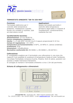
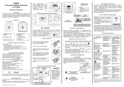
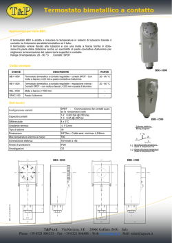
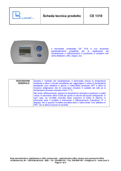
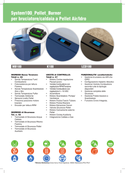
Termoregolazione - Thermoregulation
0681ML Maggio 2014 - May 2014
Termostato ambiente con sonda di temperatura e
umidità K492B
Room thermostat K492B
ISO
9001
0006/7
ISO
14001
0032A/3
OHSAS
18001
0064L/1
• Storage conditions: -20÷70 °C, 10 to 90 % rH non-cond.
• Environmental pollution: 2
• PTI of insulating materials: PCB: from 175 to 249; insulation material: PTI 275
• Software class and structure: A
• Index of protection of the case: IP20
• Category of resistance to heat and fire: D
• Classification according to protection against electric shock: to be integrated into
class 1 or 2 appliances
• Period of electrical stress across the insulating parts: long
• Immunity against voltage surges: category II
• Precision of temperature measurement: range 0÷40 °C: ±1 °C; over: ±1.5 °C
Tastiera - Keypad
K492B
Descrizione - Description
Il termostato ambiete K492B è il terminale Giacomini che, unito al modulo
di regolazione KPM30 e KPM31, permette all’utente la regolazione della
temperatura e dell’umidità di un ambiente. È dotato di sonda di temperatura
e umidità. L’alimentazione è di 230 Vac. Il termostato K492B è compatibile
con le principali scatole da incasso a muro presenti nel mercato (IT, USA, DE,
CN). L’impostazione di temperatura e umidità avviene in maniera semplice
e intuitiva grazie alla manopola frontale. La regolazione e le visualizzazioni
dipendono esclusivamente dal modulo di regolazione (KPM30 o KPM31) al
quale il termostato K492B è connesso. L’ingombro limitato e il design elegante
infine consentono una facile adattabilità a tutti i tipi di ambienti.
The K492B thermostat is the Giacomini room terminal that, together with KPM30
and KPM31 regulation module, allows the user the control the temperature and
humidity in residential environments. It is fi tted with a temperature and humidity
probe. Power supply is 230 Vac. The K492B thermostat is compatible with the main fl
ush mount distribution boxes available on the market (IT, US, DE, CN). Temperature
and humidity set is simple and intuitive, using the knob on the front panel. The type
of control and displays depend exclusively on the regulation unit (KPM30 or KPM31)
that K492B thermostat is connected to. The compact dimensions and elegant design
make it suitable for all types of rooms.
Versioni e codici - Versions and product codes
Codice
Product code
Alimentazione
Power supply
K492BY002
230 Vac
Dati tecnici - Technical data
• Alimentazione: 230 Vac (+10 …-15 %) 50/60 Hz
• Assorbimento massimo: 2 VA
• Condizioni di funzionamento: -10÷60 °C, 10...90 % U.R. non condensante
• Condizioni di immagazzinamento: -20÷70 °C, 10...90 % U.R. non condensante
• Inquinamento ambientale: 2
• PTI dei materiali di isolamento: PCB: da 175 a 249; materiale isolamento: PTI 275
• Classe e struttura del software: A
• Grado di protezione dell’involucro: IP20
• Categoria di resistenza al calore e al fuoco: D
• Classificazione secondo protezione contro scosse elettriche: da integrare in
apparecchi di classe I o II
• Periodo sollecitazioni elettriche delle parti isolanti: lungo
• Immunità contro sovratensioni: categoria II
• Precisione della misura di temperatura: range 0÷40 °C: ±1 °C; oltre: ±1,5 °C
• Power supply: 230 Vac (+10...-15%) 50/60 Hz
• Maximum current: 2 VA
• Operating conditions: -10÷60 °C, 10 to 90 % rH non-cond.
Il significato dei tasti e delle visualizzazioni può variare in funzione del modulo
di regolazione (KPM30 o KPM31) a cui il termostato K492B è collegato. Se
compare la scritta “CN” sul display significa che non c’è comunicazione con
il modulo di regolazione al quale è connesso. All’accensione del terminale è
normale la visualizzazione di “CN” per circa 30s, fino a quando non si stabilisce
la comunicazione. Nel caso poi nella parte bassa compaia la scritta “Init”
significa che il terminale è in fase di inizializzazione da parte del modulo
di regolazione. Una permanenza in questo stato superiore ai 10 minuti è
sintomo di problemi di comunicazione.
The meaning of the buttons and the displays may vary according to the regulation
unit (KPM30/KPM31) to which the K492B thermostat is connected. If “CN” is shown
on the display, it means there is no communication with the regulation unit the
terminal is connected to. On power-up, the terminal normally shows “CN” for
around 30s, until communication is established. If “Init” is shown at the bottom,
the terminal is being initialised by the regulation unit. If this process lasts more
than 10 minutes it means there are communication problems.
Tasto
Button
Descrizione
Description
Funzione
Function
Funzione
Mode
MODE
Tasto non programmato
Not programmable button
POWER
Accensione/spegnimento del K492BY002; in alcuni menù la
pressione breve rappresenta l’equivalente dell’opzione ESC.
K492BY002 device On/Off ; in some menus pressing the button
briefly is the same as choosing ESC.
Manopola regolaz. Ruotare la manopola per impostare il valore e premere per
confermare
Knob
Turn the knob to set the value and press to confirm
CLOCK
Tasto non programmato
Not programmable button
FAN
Tasto non programmato
Not programmable button
Accesso ai menù speciali: MODE + CLOCK per 3s per accedere al menù
allarmi, attivo solo se l’icona
è accesa. Gli allarmi visualizzati dipendono
dal modulo di regolazione al quale il termostato K492B è collegato.
Per accedere al menù parametri premere contemporaneamente i tasti FAN
e POWER per 3s.
Impostando password diverse è possibile accedere a menu diversi.
Con psw 22 si accede al menu parametri del K492B tra i quali “ADDR” per
l’impostazione dell’indirizzo seriale (con bus Giacomini da 128 a 143):
- “Baud” per l’impostazione del baud rate (“0”= 4800 bps, “1”= 9600 bps, “2”=
19200 bps) da impostare su “2”
- “Pcal” per calibrazione sonda.
Accessing the special menu: MODE + CLOCK for 3s to access the alarms menu,
active only if the
icon is on.
The alarms displayed depend on the regulation unit that K492B thermostat is
connected to. To access the parameters menu, press FAN and POWER together for 3s.
Diff erent passwords can be entered to access diff erent menus.
Psw 22 accesses the K492B parameters menu, which includes “ADDR” for setting the
serial address (with Giacomini bus from 128 to 143):
- “Baud” for setting the baud rate (“0”= 4800 bps, “1”= 9600 bps, “2”= 19200 bps)
to set on “2”
- “Pcal” for calibrating the probe.
1
Termoregolazione - Thermoregulation
0681ML Maggio 2014 - May 2014
Termostato ambiente con sonda di temperatura e
umidità K492B
Room thermostat K492B
Display - Display
ISO
9001
0006/7
ISO
14001
0032A/3
OHSAS
18001
0064L/1
a cerniera. Assicurarsi che i fili elettrici entrino in sede, per avere il corretto
fissaggio a scatto.
To fit the rear part of the terminal use a fl ush mount box with a min. diameter of 65
mm and a minimum depth of 31 mm.
1. detach the front from the rear of the terminal using a screwdriver (Fig. 1)
2. disconnect the 4-pin connector from the front part (Fig. 2)
3. make the electrical connections: see Fig. 3
4. fasten the rear to the fl ush mount box using the 2 screws supplied
5. plug the 4-pin connector back in
6. finally reposition the terminal, starting from the bottom tabs using a hinge
movement. Make sure that the electrical wires are in position to ensure the terminal
clicks into place.
Legenda - Legend
1
Modalità di funzionamento - Operating mode
2
Campo principale - Main field
3
Unità di misura temperatura - Temperature unit of measure
4
Set point - Set point
5
Umidità relativa - Relative humidity
6
Giorno della settimana - Day of the week
7
Campo secondario - Secondary fi eld
Nota. Note.
La visualizzazione di alcune funzioni è legata al modulo di controllo
(KPM30/KPM31).
Fig.1
Fig.3
The display of some functions is related to the control module (KPM30/
KPM31).
Avvertenza per l’installazione - Installation warnings
• Questi terminali sono stati progettati per il montaggio a incasso, con scatola
conforme alle normative vigenti;
• prima di eff ettuare qualsiasi operazione sul terminale, togliere l’alimentazione
dal dispositivo portando l’interruttore principale del quadro elettrico su OFF.
Rimuovere quindi la parte frontale del terminale e quindi quella posteriore
per eff ettuare i collegamenti elettrici;
• per la connessione seriale utilizzare un cavo tripolare schermato, AWG 2022. La lunghezza della rete non deve superare i 500 m. Per reti molto estese
aggiungere una resistenza da 120 Ohm tra RX/TX+ e RX/TX- del primo e
dell’ultimo dispositivo per evitare possibili problemi di comunicazione.
• la connessione tra i dispositivi bus deve essere necessariamente effettuata
“a catena”.
• These terminals have been designed for fl ush mount assembly, on distribution
boxes compliant with the standards in force;
• before performing any operations on the terminal, disconnect the power supply
from the device by switching the main switch on the electrical panel OFF. Then
remove the front part of the terminal from the rear to make the electrical connections;
• for the serial connection use three-wire shielded cable, AWG 20-22. The length
of the network must not exceed 500 m. For extended networks fi t a 120 Ohm
resistor between RX/TX+ and RX/TX- on the fi rst and last device, to avoid possible
communication problems.
• the connections between the devices must be “chain” shape.
Montaggio - Assembly
Per montare la parte posteriore occorre almeno una scatola a incasso Ø 65
mm e profondità 31 mm.
1. separare la parte anteriore da quella posteriore del terminale utilizzando
un cacciavite (fig.1)
2. scollegare il connettore a 4 poli dalla parte anteriore (fig.2)
3. effettuare i collegamenti elettrici: fig.3
4. fissare la parte posteriore alla scatola da incasso con le 2 viti a corredo
5. reinserire il connettore a 4 poli
6. rimontare infine il terminale, partendo dai dentini inferiori con un movimento
Fig.2
Smontaggio - Dismantling
Inserire un cacciavite nella fessura superiore (fig.1) e premere verso il basso
per estrarre il display.
Insert a screwdriver into the clot at the top (Fig. 1) and press downwards to detach
the display.
2
Termoregolazione - Thermoregulation
0681ML Maggio 2014 - May 2014
Termostato ambiente con sonda di temperatura e
umidità K492B
Room thermostat K492B
ISO
9001
0006/7
ISO
14001
0032A/3
OHSAS
18001
0064L/1
Dimensioni - Dimensions
Dimensioni termostato [mm]
Avvertenza. Warning.
Evitare l’installazione del terminale in ambienti che presentino le
seguenti caratteristiche:
• umidità relativa maggiore di quanto indicato;
• forti vibrazioni o urti;
• esposizione a getti d’acqua;
• esposizione ad atmosfere aggressive ed inquinanti (es.: gas solforici
e ammoniacali, nebbie saline, fumi) con conseguente corrosione e/o
ossidazione;
• elevate interferenze magnetiche e/o radiofrequenze (ad esempio
vicino ad antenne trasmittenti);
• esposizione all’irraggiamento solare diretto e agli agenti atmosferici
in genere;
• ampie e rapide fl uttuazioni della temperatura ambiente;
• ambienti ove sono presenti esplosivi o miscele di gas infiammabili;
• esposizione alla polvere (formazione di patina corrosiva con possibile
ossidazione e riduzione dell’isolamento).
Dimensioni elemento posteriore [mm]
Avoid installing the terminal in environments with the following
characteristics:
• relative humidity greater than the value specified;
• strong vibrations or knocks;
• exposure to water sprays;
• exposure to aggressive and polluting atmospheres(e.g.: sulphur and
ammonia fumes, saline mist, smoke) so as to avoid corrosion and/or
oxidation;
• strong magnetic and/or radio frequency interference (for example, near
transmitting antennae);
• exposure to direct sunlight or the elements in general;
• large and rapid fl uctuations in the room temperature;
• environments where explosives or mixes of fl ammable gases are present;
• exposure to dust (formation of corrosive patina with possible oxidation
and reduction of insulation).
Schemi elettrici - Electrical schemes
Testi di capitolato - Product specifications
K492B
Termostato ambiente con display retroilluminato ed interfaccia locale per il controllo della temperatura e umidità ambiente. Da utilizzare con collegamento via
bus al modulo di regolazione KPM30 o KPM31. Alimentazione 230 Vac, comunicazione Modbus RTU slave su RS485. Installazione da incasso in scatola civile tonda.
Certificazione CE.
Room thermostat with backlight display and local interface to manage the room temperature and humidity. To use in combination with regulation units KPM30 or KPM31
by bus connection. Modbus RTU slave on RS485. Wall mounting installation in round civil box. CE certification.
3
Termoregolazione - Thermoregulation
0681ML Maggio 2014 - May 2014
Termostato ambiente con sonda di temperatura e
umidità K492B
Room thermostat K492B
ISO
9001
0006/7
ISO
14001
0032A/3
OHSAS
18001
0064L/1
Altre informazioni
Per ulteriori informazioni consultare il sito www.giacomini.com o contattare il servizio tecnico: ' +39 0322 923372 6 +39 0322 923255 * [email protected]
Questa comunicazione ha valore indicativo. Giacomini S.p.A. si riserva il diritto di apportare in qualunque momento, senza preavviso, modifiche per ragioni tecniche o commerciali agli articoli
contenuti nella presente comunicazione. Le informazioni contenute in questa comunicazione tecnica non esentano l’utilizzatore dal seguire scrupolosamente le normative e le norme di
buona tecnica esistenti. Giacomini S.p.A. Via per Alzo, 39 - 28017 San Maurizio d’Opaglio (NO) Italy
Additional information
For additional information please check the website www.giacomini.com or contact the technical service: ' +39 0322 923372 6 +39 0322 923255 * [email protected]
This pamphlet is merely for information purposes. Giacomini S.p.A. retains the right to make modifications for technical or commercial reasons, without prior notice, to the items described in
this pamphlet. The information described in this technical pamphlet does not exempt the user from following carefully the existing regulations and norms on good workmanship.
Giacomini S.p.A. Via per Alzo, 39 - 28017 San Maurizio d’Opaglio (NO) Italy
4
© Copyright 2026 Paperzz