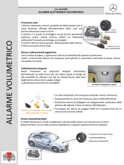
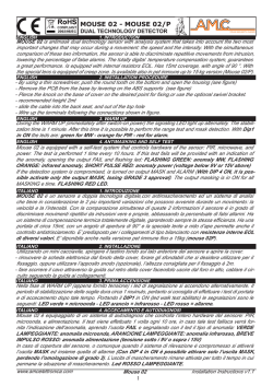
mpa
o
Per 1 elettrop
QUADRI ELETTRICI
CONTROL PANELS
For 1 electric
Serie
DRENA 1
pump
Data 31/01/’14
Mod. Q
Quadri elettrici per pompe sommergibili e di superficie.
Control panels for surface and submersible electric pumps.
ITA
ENG
Descrizione generale
General description
Quadro elettronico per 1 pompa da drenaggio.
Serie di quadri elettronici sviluppata per il
comando e la protezione di una elettropompa
sommergibile per drenaggio e svuotamento acque
reflue o fluidi particolarmente viscosi.
Electronic control panel for 1 sewage pump.
Series of electronic control panels developed to
control and protect 1 submersible single-phase
or three-phase electric pump for drainage and
emptying of dirty water or viscous liquids.
Dati tecnici -Technical data
Potenza indicativa - Approx. power
Codice
Code
Modelli
Models
01.300
01.301
01.302
01.303
01.304
DRENA 1-Mono
DRENA 1-Tri/4
DRENA 1-Tri/5,5
DRENA 1-Tri/7,5
DRENA 1-Tri/11
Trifasee 400 V
Three-phase 400 V
Monofase 230 V
Single-phase 230 V
HP 0,4÷3
kW 0,3÷2,2
HP 0,4÷5,5
HP 0,75÷7,5
HP 0,75÷10
HP 10÷15
kW 0,3÷4
kW 0,55÷5,5
kW 0,55÷7,5
kW 7,5÷11
Corrente max (A)
Max current (A)
16
8
11
15
24
A
B
P
Kg.
1,5
320 240 190
2
2,5
3
A
B
P
Caratteristiche - Feature
Descrizione
• Quadro elettronico;
• Alimentazione 1 ~ 50/60Hz 230V±10% (DRENA 1-Mono);
• Alimentazione 3 ~ 50/60Hz 400V±10% (DRENA 1-Tri);
• Ingressi e circuiti di comandi in bassa tensione;
• Ingresso normalmente aperto per comando di avviamento;
Description
• Electronic control panel;
• Power supply 1~50/60 Hz 230V ±10% (DRENA 1-Mono);
• Power supply 3~50/60 Hz 400V ±10% (DRENA 1-Tri);
• Auxiliaries contacts and circuits in low voltage;
• Normally open contact for start;
• Ingresso normalmente aperto per comando di minimo livello/pressione/ • Normally open contact for minimum level/pressure/stop contact or input for 3 level
arresto o per 3 sonde unipolari ;
probes;
• Ingresso normalmente aperto per attivazione allarme 12Vcc 200mA;
• Ingresso per clicson motore;
• Pulsanti Automatico-0/Reset-Manuale (momentaneo);
• Normally open contact for alarm activation 12Vcc 200mA ;
• Normally open contact for clicson of the motor;
• Push-buttons for selecting Auto-Off/Reset-Manual (temporary) operation;
• Selettore dip-switch per funzionamento sonde in Riempimento/Svuota• Dip-switch selector for probes operating in filling/emptying mode;
mento;
• Led verde di presenza rete;
• Led verde automatico inserito;
• Led verde motore attivo;
• Led rosso allarme livello;
• Led rosso allarme motore in sovraccarico;
• Led rosso allarme attivazione clicson motori;
• Controllo elettronico per sovraccarico motore regolabile;
• Protezione ausiliari e motore con fusibili;
• Uscita allarme (com-na-nc carico resistivo);
• Sezionatore generale bloccoporta;
• Predisposizione per condensatore di marcia (non incluso);
• Box in ABS, IP55;
• Temperatura ambiente: -5/+40 °C;
• Umidità relativa 50% a 40 °C (non condensata).
• Green led indicating mains supply;
• Green led indicating motor running;
• Green led indicating automatic operation;
• Red led indicating level alarm;
• Red led indicating motor overload;
• Red led indicating clicson alarm;
• Adjustable overload electronic protection;
• Auxiliaries and motor protection fuses;
• Alarm output (com-no-nc resistive load);
• Main switch interlocking door;
• Running capacitor can be added (not included);
• Enclosure in ABS, IP55;
• Ambient temperature: -5/+40 °C;
• Relative humidity 50% at 40 °C (not condensed).
Il costruttore si riserva il diritto di modificare le caratteristiche tecniche senza preavviso.
The manufacturer reserves the right to modify the technical features without previous notice.
Z1.a
Optional
Mod.
98.003 - AA/C
98.004 - LL/C
98.005 - DBT/C
Caratteristiche - Features
• Allarme sonoro cablato.
• Acoustic alarm wired on the panel.
Sirena 90 dB ingresso comando da galleggiante o pressostato.
Sounder 90 dB: input from float switch or pressure switch.
• Allarme visivo cablato.
• Flashing alarm wired on the panel.
Attivazione da galleggiante o pressostato..
Activation from float switch or pressure switch.
• Dispositivo per allarme con batteria in tampone.
• Wired equipment for alarm with buffer battery
(Abbinabile ai codici AA/C e LL/C) cablato.
(for items AA/C and LL/C)
Schemi di collegamento - Connection diagrams
SCHEMA COLLEGAMENTO - ELECTRONIC BOARD
DRENA 1-Mono
SCHEDA DRENA 1 MONOFASE
CONDENSATORE
AVVIAMENTO
DRENA 1 Single-phase wiring diagram
STARTING
CAPACITOR
NC
NA
U1
OUT ALARM
J3
J4
N
AVV
PE
PE
N
L
IN RETE
OUT MOTOR
USCITA MOTORE
1~N230V +/-10%
CUMULATIVE ALARM OUTPUT
USCITA ALLARME CUMULATIVO
SONDE DI LIVELLO
C
LEVEL PROBES
GALLEGGIANTE/PRESSOSTATO
COM MIN MAX COM
IN SONDE/Gmin
FLOAT/PRESSURE SWITCH
IN
G1/P1
MOTOR CLICSON
ALARM FLOAT SWITCH
GALLEGGIANTE DI ALLARME
KLIXON
T1
CLICSON MOTORE
OUT 12 Vcc
ALARM
G.A.
(MONOFASE / SINGLE-PHASE)
MOTOR OUTPUT
1~N230V +/-10%
2T1
4T2
6T3
INGRESSO
ALIMENTAZIONE
1~N230V +/-10%
MAINS SUPPLY INPUT
1~N230V +/-10%
SCHEMA COLLEGAMENTO - ELECTRONIC BOARD
DRENA 1-Tri/-
(TRIFASE / THREE-PHASE)
SCHEDA DRENA 1 TRIFASE
DRENA 1 Three-phase wiring diagram
C
NC
NA
Il costruttore si riserva il diritto di modificare le caratteristiche tecniche senza preavviso.
CUMULATIVE ALARM OUTPUT
USCITA ALLARME CUMULATIVO
OUT ALARM
LEVEL PROBES
GALLEGGIANTE/PRESSOSTATO
COM MIN MAX COM
IN SONDE/Gmin
SONDE DI LIVELLO
IN
G1/P1
FLOAT/PRESSURE SWITCH
KLIXON
T1
MOTOR CLICSON
ALARM FLOAT SWITCH
GALLEGGIANTE DI ALLARME
ALARM
G.A.
CLICSON MOTORE
OUT 12 Vcc
U1
N
AVV
PE
PE
N
L
IN RETE
OUT MOTOR
TELERUTTORE
CONTACTOR
2T1
2T1
4T2
6T3
4T2
6T3
14NO
USCITA MOTORE
3~400V +/-10%
INGRESSO
ALIMENTAZIONE
3~400V +/-10%
MOTOR OUTPUT
3~400V +/-10%
MAINS SUPPLY INPUT
3~400V +/-10%
The manufacturer reserves the right to modify the technical features without previous notice.
Timbro del rivenditore - Retailer’s stamp
AFPUMPS s.r.l.
Via dell’Artigianato n. 4
35020 PERNUMIA (PD) ITALY
Tel. (+39) 0429 778295 r.a.
Fax. (+39) 0429 763049
www.afpumps.com
Z1.b
[email protected]
© Copyright 2026 Paperzz