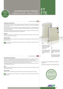
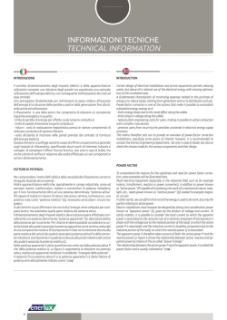
PRT
DPRT
CONDENSATORI TRIFASE
THREE-PHASE CAPACITORS
rifasamento
fisso
fixed
power-factor
TECNOLOGIA COSTRUTTIVA
I condensatori autorigenerabili serie PRT sono costituiti da tre elementi monofase realizzati in film
di polipropilene metallizzato ad alto gradiente collegati a triangolo ed inseriti in custodia cilindrica
di alluminio estruso, con codolo di fissaggio M12 x 12 mm utilizzato per la messa a terra del condensatore.
La chiusura del condensatore viene realizzata tramite la bordatura del disco in acciaio sulla custodia in alluminio, garantendo una perfetta ermeticità. Sul disco in acciaio è assemblata ermeticamente e dielettricamente la basetta in nylon rinforzato con fibra di vetro dove sono disposti i tre
terminali di fissaggio.
Si consiglia di lasciare almeno 25 mm di spazio libero al di sopra della basetta di collegamento per consentire un corretto funzionamento del dispositivo a sovrapressione.
I condensatori serie PRT possono anche essere prodotti in una versione a secco. Questi condensatori non sono prodotti standard a magazzino, ma vengono prodotti su richiesta. In caso di richiesta
il codice di ordinazione va completato con la lettera “D” davanti al codice del prodotto.
Se si richiedono tempi di scarica più bassi si devono adottare resistenze di scarica rapida (fornibili su
richiesta) che permettono al condensatore di scaricarsi in pochi secondi.
INSTALLAZIONE
L’installazione deve essere eseguita tramite il fissaggio del codolo M12 del Condensatore.
I prodotti descritti sono suscettibili in qualsiasi momento di evoluzioni o di
modifiche. Le descrizioni ed i dati a catalogo non possono pertanto avere
alcun valore contrattuale.
Technical data and descriptions in the pubblication are accurate, to the
best of our knoweledge, but no liabilities for errors, omissions or contingencies arising therefrom are accepted.
CONSTRUCTION TECHNOLOGY
The self-healing capacitors in the PRT series consist of three single-phase elements made of metallized
polypropylene film at high gradient with a delta connection and in a cylindrical casing of extruded
aluminium, with a fixing spigot M12 x 12 mm used to earth the capacitor.
The capacitor is closed with the beading of the steel disc on the aluminium casing, ensuring perfect air
and water tightness. The fibreglass-reinforced nylon strip is dielectrically assembled on the steel disc
with an airtight fit. The strip accommodates the three terminals.
consultare “GUIDA
ALLA SCELTA DEL
PRODOTTO” a pag. 20
carefully check “GUIDE TO
THE CHOISE OF THE
PRODUCT” pag 20
It is therefore recommended to leave at least 25 mm of clear space above the connecting strip to
allow the overpressure device to work properly.
PRT capacitor series can also be realized in a dry version. Dry capacitors are not standard stock items
but production is on request. In case of request the purchase order code must be completed with the
letter “D” before product code.
If lower discharge times are required, it is necessary to use fast discharge resistors (supplied on request)
that enable the capacitor to discharge in just a few seconds.
INSTALLATION
Installation must be performed by fixing the M12 spigot of the Capacitor.
24
CONDENSATORI TRIFASE
THREE-PHASE CAPACITORS
PRT-DPRT
PRT
A
µF
230
230
230
230
400
400
400
400
400
400
400
400
400
400
415
415
415
415
415
415
415
415
415
415
440
440
440
440
440
440
440
440
440
440
440
440
480
480
480
480
480
480
525
525
525
525
525
525
525
525
525
690
690
690
690
690
12.59
18.89
25.13
31.4
7.20
10.83
14.40
18.00
21.60
28.90
36.08
43,35
57,80
72,25
6.96
10.45
13.93
17.41
20.90
27.86
34.82
41.78
55.71
69.64
6.56
9.85
13.13
16.42
18.39
19.70
26.28
32.85
34.82
39.42
52.50
65.69
6.02
12.04
15.05
18.06
24.08
30.10
5.51
8.26
11.01
13.76
16.52
20.46
22.02
27.53
40.84
8.38
10.47
12.57
16.75
20.92
3 x 100.3
3 x 150.3
3 x 200.6
3 x 250.6
3 x 32.2
3 x 49.7
3 x 66.3
3 x 82.9
3 x 99.5
3 x 132.6
3 x 165.8
3 x 199,0
3 x 266,6
3 x 331.7
3 x 30.8
3 x 46.2
3 x 61.6
3 x 77.0
3 x 92.4
3 x 123.2
3 x 154.0
3 x 184.9
3 x 246.5
3 x 308.2
3 x 27.4
3 x 41.0
3 x 54.8
3 x 68.5
3 x 76.7
3 x 82.2
3 x 109.6
3 x 137.0
3 x 154
3 x 164.0
3 x 219.3
3 x 274,1
3 x 23.0
3 x 46.0
3 x 57.6
3 x 69.1
3 x 92,1
3 x 115,2
3 x 19.2
3 x 28.9
3 x 38.5
3 x 48.1
3 x 57.7
3 x 71.3
3 x 77.0
3 x 96.2
3 x 143
3 x 22.3
3 x 27.8
3 x 33.4
3 x 44.5
3 x 56.0
Ø (mm)
75
85
100
100
75
75
75
75
85
85
100
100
120
120
75
75
75
85
85
85
100
100
120
120
75
75
75
75
75
85
85
100
100
100
120
120
75
75
75
75
85
100
75
75
75
75
85
100
100
100
100
75
75
85
100
100
H (mm)
238
238
238
285
163
163
201
238
201
238
238
276
238
280
163
163
201
238
201
238
238
276
238
280
163
163
201
238
238
238
238
238
238
238
238
238
163
163
238
238
238
238
163
163
201
238
238
238
238
238
276
238
238
238
238
238
CONFEZIONE PZ.
PACKING PCS
12
12 15
15 12
12
12
12
12
12 15 15 6
6
12
12 12
12
12 12
15
15 6
6
12
12
12
12
12
12
12 15 15
15
6
6
12 12
12
12 15
15
12 12
12
12
12 15
15 15
15
12 12
12
15 15 Terminali 16 mm2
Terminals 16 mm2
30
5.0
7.5
10.0
12.5
5.0
7.5
10.0
12.5
15.0
20.0
25.0
30.0
40.0
50.0
5.0
7.5
10.0
12.5
15.0
20.0
25.0
30.0
40.0
50.0
5.0
7.5
10.0
12.5
14.0
15.0
20.0
25.0
28.1
30.0
40.0
50.0
5.0
10.0
12.5
15.0
20.0
25.0
5.0
7.5
10.0
12.5
15.0
19.0
20.0
25.0
37.1
10.0
12.5
15.0
20.0
25.0
V
÷
÷
H±2
PRT.2350
PRT.2375
PRT.2310
PRT.2312
PRT.4005
PRT.4007
PRT.4010
PRT.4012
PRT.4015
PRT.4020
PRT.4025
PRT.4030
PRT.4040
PRT.4050
PRT.4105
PRT.4107
PRT.4110
PRT.4112
PRT.4115
PRT.4120
PRT.41250
PRT.4130
PRT.4140
PRT.4150
PRT.4405
PRT.4407
PRT.4410
PRT.4412
PRT.4414
PRT.4415
PRT.4420
PRT.4425
PRT.4428
PRT.4430
PRT.4440
PRT.4450
PRT.4805
PRT.4810
PRT.4812
PRT.4815
PRT.4820
PRT.4825
PRT.5205
PRT.5207
PRT.5210
PRT.5212
PRT.5215
PRT.5219
PRT.5220
PRT.5225
PRT.5237
PRT.6910
PRT.6912
PRT.6915
PRT.6920
PRT.6925
kvar
12
CODICE
REFERENCE
DIMENSIONI / DIMENSIONS
M12
ø±1
Resistenza di scarica
Discharge resistor
15
15
ø±1
25
PRT-DPRT
CONDENSATORI TRIFASE
THREE-PHASE CAPACITORS
CARATTERISTICHE TECNICHE
Condensatore ø 120 mm
Capacitor ø 120 mm
Tensione nominale (Un)
Frequenza nominale
TECHNICAL PARTICULARS
230 - 400 - 415 - 440 - 480 - 525 - 690 V
35
Tolleranza sulla capacità
Perdite totali (ai morsetti)
Temperature class
≤ 0,2 W/kvar
Dielectric losses
≤ 0,4 W/kvar
Total losses (at the terminals)
1,5 In
Livello di isolamento
Insulation level
3/15 kV Ue ≤ 660 Vac
Massimo valore di cresta del transitorio di corrente
Prova di Tensione tra i terminali
Max. permitted current
≤ 200 In
Maximum peak value of the current transient
2,15 Un per 2’’ - 2.15 Un for 2’’
Prova di Tensione tra i terminali e la cassa
Terminali
3,6 KV per 10”
Voltage test between the terminals
Voltage test between the terminals and contanier
Fastom
Terminals
Esterne (riduzione a 75 V entro 3 min)
External (reduction to 75 V within 3 min)
Resistenze di Scarica
Discharge resistors
÷
Servizio
Continuo - Continuous
H±2
Installazione
Raffreddamento
Grado di protezione
IP 20 (75-85-100) IP00 (ø 120)
Durata vita prevista
>130.000 h (classe D) - >150.000 h (classe C)
12
Resistenza
di scarica
Discharge
resistor
ø±1
Altitude
Degree of protection
Expected life
Fixing
CEI EN 60831-1/2, IEC 60831-1/2
Reference standards
Max 5000 operazioni di manovra all’anno in accordo con norme IEC 60831-1
Max 5000 switchings per year according to IEC 60831-1
Altre caratteristiche realizzabili su richiesta.
Terminali
a Vite M10
Terminals
screw M10
Cooling
Max permissible humidity
Tramite codolo M12 in qualsiasi posizione
With M12 spigot in any position
Norme di riferimento
ø±1
Aria Naturale o forzato - Natural or forced air
≤ 2000 (m s.l.m. - m a.s.l.)
Fissaggio
M12
Installation
80%
Altitudine
Manovre
Service
Interno - Indoor
Umidità max accettabile
26
Tolerance on capacitance
- 25 ° C / + 55 ° C
Massima corrente ammessa
÷
Rated frequency
- 5% ÷ + 10%
Classe temperatura
Perdite dielettriche
Rated voltage (Un)
50 Hz (60 Hz a richiesta) - 50 Hz (60 Hz on request)
Number of switching operation
Other characteristics can be made on request.
© Copyright 2026 Paperzz