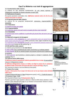
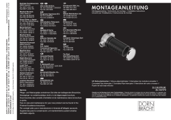
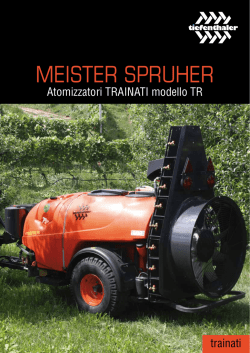
www.cembre.com
Cembre S.p.A.
Via Serenissima, 9
25135 Brescia (Italia)
Telefono: 030 36921
Telefax: 030 3365766
E-mail: [email protected]
www.cembre.it
Cembre España S.L.
Calle Verano, 6 y 8 - P.I. Las Monjas
28850 Torrejón de Ardoz - Madrid (España)
Teléfono: 91 4852580
Telefax: 91 4852581
E-mail: [email protected]
www.cembre.es
Cembre Ltd.
Dunton Park
Kingsbury Road, Curdworth - Sutton Coldfield
West Midlands B76 9EB (Great Britain)
Tel.: 01675 470440 - Fax: 01675 470220
E-mail: [email protected]
www.cembre.co.uk
Cembre AS
Fossnes Senter
N-3160 Stokke (Norway)
Phone: (47) 33361765
Telefax: (47) 33361766
E-mail: [email protected]
www.cembre.no
Cembre S.a.r.l.
22 Avenue Ferdinand de Lesseps
91420 Morangis (France)
Tél.: 01 60 49 11 90 - Fax: 01 60 49 29 10
B.P. 37 - 91421 Morangis Cédex
E-mail: [email protected]
www.cembre.fr
Cembre GmbH
Heidemannstraße 166
80939 München (Deutschland)
Telefon: 089/3580676
Telefax: 089/35806777
E-mail: [email protected]
www.cembre.de
ENGLISH
FRANÇAIS
DEUTSCH
ESPAÑOL
Certified Quality
Management System
Cembre Inc.
Raritan Center Business Park
181 Fieldcrest Avenue
Edison, New Jersey 08837 (USA)
Tel.: (732) 225-7415 - Fax: (732) 225-7414
E-mail: [email protected]
24
www.cembreinc.com
Certified Environmental
Management System
Certified Occupational
Health & Safety
Management System
ITALIANO
CLAMPING DEVICE
SUPPORT DE BLOCAGE
SCHIENENFUSSBEFESTIGUNG
DISPOSITIVO DE BLOQUEO
DISPOSITIVO DI BLOCCAGGIO
DBSN
cod. 6261062
This manual is the property of Cembre: any reproduction is forbidden without written permission.
Ce manuel est la proprieté de Cembre: toute reproduction est interdite sauf autorisation écrite.
Der Firma Cembre bleibt das Eigentumsrecht der Bedienungsanleitung vorbehalten.
Ohne vorherige schriftliche Genehmigung darf die Bedienungsanleitung weder vollständig noch teilweise vervielfältigt werden.
Este manual es propiedad de Cembre. Toda reproducción está prohibida sin autorización escrita.
Questo manuale è di proprietà della Cembre: ogni riproduzione é vietata se non autorizzata per scritto.
09 M 059
OPERATION AND MAINTENANCE MANUAL
NOTICE D'UTILISATION ET ENTRETIEN
BEDIENUNGSANLEITUNG
MANUAL DE USO Y MANTENIMIENTO
MANUALE D'USO E MANUTENZIONE
1
NOTE
WARNING - PRECAUTION D'USAGE HINWEISE - ADVERTENCIA - AVVERTENZA
––––––––––––––––––––––––––––––––––––––––––––––––––––––––––––
− For operator safety, the DBSN device for clamping the drill to flanged
rails must only be used outside the rails, not between them.
− Carefully comply with the safety provisions applicable to works carried
out on tracks involving the passage of trains.
− Pour la sécurité des opérateurs, la machine doit être placée EXTERIEUR
à la voie.
− Observer scrupuleusement les prescriptions sur la sécurité prévues pour
les travaux sur les tronçons intéressés par le passage des convois.
− Aus Sicherheitsgründen darf die Bohrmaschine bei der Verwendung mit
der Befestigung Typ DBSN nur von aussen an den Gleisen befestigt
werden. Niemals zwischen den Schienen.
− Bitte halten Sie sich gewissenhaft an die vorgegebenen Sicherheitsvor schriften bei Tätigkeiten im Gleisbereich in denen Zugverkehr
stattfindet.
− Por motivos de seguridad el taladro equipado con dispositivo de bloqueo
al pie del raíl tipo DBSN, no debe nunca ser fijado entre los dos raíles en
el interior de la vía, sino siempre en el exterior.
− Siga meticulosamente las instrucciones de seguridad previstas para
trabajos en vías por las que pasen trenes.
––––––––––––––––––––––––––––––––––––––––––––––––––––––––––––
–––––––––––––––––––––––––––––––––––––––––––––––––––––––––-------------------–––––------––––––––––––––––––––––––––––––––––––––––––
––––––––––––––––––––––––––––––––––––––––––––––––––––––––––––
––––––––––––––––––––––––––––––––––––––––––––––––––––––––––––
–––––––––––––––––––––––––––––––––––––––––––––––––––––––––-------------------–––––------––––––––––––––––––––––––––––––––––––––––––
––––––––––––––––––––––––––––––––––––––––––––––––––––––––––––
––––––––––––––––––––––––––––––––––––––––––––––––––––––––––––
− Per motivi di sicurezza, il trapano con dispositivo di bloccaggio al piede
della rotaia DBSN, non deve essere fissato mai tra le due rotaie, ma
sempre all'esterno.
− Attenersi scrupolosamente alle prescrizioni di sicurezza previste per
lavori su tratte interessate dal passaggio di convogli.
–––––––––––––––––––––––––––––––––––––––––––––––––––––––––-------------------–––––------––––––––––––––––––––––––––––––––––––––––––
––––––––––––––––––––––––––––––––––––––––––––––––––––––––––––
––––––––––––––––––––––––––––––––––––––––––––––––––––––––-----
2
23
ENGLISH
DBSN CLAMPING DEVICE
NOTE
––––––––––––––––––––––––––––––––––––––––––––––––––––––––––––
––––––––––––––––––––––––––––––––––––––––––––––––––––––––––––
–––––––––––––––––––––––––––––––––––––––––––––––––––––––––------
The DBSN clamping device has been designed to attach Cembre drill to the flange of the
rail in “Non Possession” conditions. It can therefore remain in position during the passage
of trains.
The DBSN clamping device consists of:
– Clamping unit (1)
– 2 pcs special M6 screws (9)
– 2 pcs self-locking nuts (10)
– 2 pcs M6x35 screws (13)
– Thickness plate (15)
--------------–––––------––––––––––––––––––––––––––––––––––––––––––
9
10
15
1
––––––––––––––––––––––––––––––––––––––––––––––––––––––––––––
13
––––––––––––––––––––––––––––––––––––––––––––––––––––––––––––
–––––––––––––––––––––––––––––––––––––––––––––––––––––––––-----FIG. 1
--------------–––––------––––––––––––––––––––––––––––––––––––––––––
––––––––––––––––––––––––––––––––––––––––––––––––––––––––––––
––––––––––––––––––––––––––––––––––––––––––––––––––––––––––––
–––––––––––––––––––––––––––––––––––––––––––––––––––––––––-------------------–––––------––––––––––––––––––––––––––––––––––––––––––
––––––––––––––––––––––––––––––––––––––––––––––––––––––––––––
––––––––––––––––––––––––––––––––––––––––––––––––––––––––-----
22
NOTE: drilling operation by drilling machine equipped with DBSN device requires
long type broach cutters (88 mm) eg A190L.
Fitting the dbsn clamping device to the drill (Ref. to Figs 3 ÷ 6).
The drill is clamped between the assembled positioning template (order separately) and the
clamping bar (2) of the DBSN device (see Fig. 3).
To fit the DBSN device on the drill proceed as follows:
– Select the positioning template for the type of rail to be drilled.
– Fit the positioning template on the DBSN clamping device by securing it with the two special
screws and nuts supplied (see Fig. 5).
Position the template approx. 90° to the base of the device, then screw up the two nuts
without fully tightening them
Note: Bear in mind that the small square “windows” in the lateral wings of the template
must face upwards (see Fig. 4).
– Lay the drilling machine on its side with advance lever upside, then withdraw the spindle
completely.
– Fit the thickness plate (15) on the front plate (90) of the drilling machine.
Pins (91) will facilitate correct location (see Fig. 6).
Fit the assembly of clamping unit (1) and the positioning template on the thickness plate
(15); clamp the positioning template by fully tightening the two relevant screws (13).
3
ENGLISH
Clamping the drilling machine to the rail flange (Ref. to Fig. 7)
To clamp the drill complete with the DBSN device to the rail, proceed as follows:
– Lift clevis (3) from its housing, so to manually slide the entire complete “bar (2) - screw (4)”
assembly into the “fully open” position.
– Insert the drill, keeping it slightly inclined downwards, underneath the rail flange near the
point to be drilled (see Fig. 7a).
– With the positioning template inserted between the head and flange of the rail, bring the
drill into the horizontal position: the rail flange must be parallel with the base of the DBSN
clamping device (see Fig. 7b).
– Slide the “bar-screw” assembly by hand into the “fully closed” position so that the bar (2)
is supported on the edge of the rail flange (see Fig. 7c).
If this cannot be achieved, adjust screw (4).
– Relocate clevis (3) and tighten screw (4) with a 19 mm socket/spanner, to achieve firm
clamping to the rail flange (see Fig. 8).
N.B.: To be able to locate clevis (03) in its working position, screw head (04) must lean
against the body of the DBSN device.
– To remove the drill from the rail proceed as follows:
– Slacken screw (4) just enough to release the clevis (3);
– Lift the clevis and slide the “bar (2) - screw (4)” assembly by hand into the fully open position, which enables the drill to be removed from the rail flange.
15
9
13
ATTENTION:
10
With a cutter/bit fitted and the drilling machine clamped to the rail, to avoid advance
lever interference in train area, ensure before drilling, that:
• The spindle shaft is completely withdrawn and the advance lever is parallel with the
axis of the rail, facing in the direction shown in Fig. 2.
• Check that the lever is not free to move.
1
36
14
5
8
FIG. 2 – INITIAL POSITIONING OF THE LEVER
4
21
FRANÇAIS
TABLE 1 - TABLEAU 1 - TABELLE 1 - TABLA 1 - TAVOLA 1
SUPPORT DE BLOCAGE DBSN
Le support DBSN a été réalisé pour obtenir le blocage de la perforatrice Cembre au patin
du rail dégageant le GABARIT, et pouvoir ainsi rester positionnée pendant le passage des
trains.
2
Le support DBSN se compose de:
– Armature de blocage (1)
– Vis (9) spéciale M6 (x2)
– Écrou (10) autobloquant (x2)
– Vis (13) M6x35 (x2)
– Plaque d’épaisseur (15)
6
9
10
12
3
15
1
13
FIG. 1
NOTE: perçage par perforatrice équipé de dispositif DBSN demande l’utilisation de
fraises frontales type longues (88 mm) ex. A190L.
Lubricate
Graisser
Einfetten
Engrasar
Ingrassare
4
7
11
20
Montage du support de blocage DBS sur la perforatrice (voir Fig. 3 ÷ 6)
Le blocage de la perforatrice s’effectuera entre le calibre de positionnement (à commander
séparément) et l’étrier de serrage (2) du support DBSN même (voir Fig. 3).
Pour monter le dispositif DBSN sur la perforatrice veuillez procéder comme il suit:
– Choisir le calibre de positionnement, approprié au type de rail à perforer.
– Fixer ce calibre sur le support DBSN sur l’armature de blocage (1) à l’aide des 2 vis (9) du
support (voir Fig. 5).
Positionner le calibre à 90° par rapport à la base du support même, ensuite le fixer à l’aide
de ces deux vis, sans serrer à fond les écrous autobloquants (10).
Note: assurez vous que les petites fenêtres carrées situées de chaque côté du calibre
soient bien positionnées en haut (voir Fig. 4).
– Placer la perforatrice sur le coté avec le levier de commande en haut, ensuite reculer
complètement le mandrin à l’aide du levier de commande.
– Placer la plaque d’épaisseur (15) sur la plaque frontale de la foreuse (90), les goupilles
(91) en définiront la position précise (voir Fig. 6).
Monter l’ensemble “armature de blocage + calibre” à la plaque d’épaisseur (15); bloquer
le calibre de positionnement en serrant les deux vis (13) à fond.
5
FRANÇAIS
Blocage au patin du rail (Voir Fig. 7)
Pour bloquer la perforatrice avec le DBSN au rail, procéder comme il suit:
– Tirer complètement vers le haut le cavalier (3) de manière à faire glisser l’ensemble “étrier
(2) - Vis (4)” en position reculée (complètement ouvert).
– Insérer la perforatrice en l’inclinant légèrement vers le bas sous le patin du rail, à proximité
du lieu de perforation (voir Fig. 7a).
– Le calibre de positionnement introduit entre champignon et patin du rail, placer la perforatrice
en position horizontale; le patin du rail doit être parallèle à la base du dispositif de blocage
DBSN (voir Fig. 7b).
– Repousser manuellement l’ensemble “étrier-boulon” vers l’avant (position complètement
fermée), de sorte que l’étrier (2) coince le patin du rail (voir Fig. 7c).
Au besoin ajuster en actionnant la vis (4).
– Serrer la vis (4) à l’aide d’une clé de 19 mm, jusqu’à voir apparaître le siège du logement
du cavalier (3) (partie non fileté de la vis) (voir Fig. 8).
Abaisser le cavalier dans son logement et bloquer la vis (4) avec la même clé de 19 mm,
on obtient ainsi le blocage de l’étrier (2).
La perforatrice “fait corps” avec le rail (voir Fig. 8).
– Pour dégager la perforatrice fixée au rail:
– Débloquer la vis (4) afin de décoincer le cavalier (3).
– Soulever complètement le cavalier (3) et faire glisser manuellement l’ensemble “étrie-vis”
en le tirant pour dégager le patin du rail.
– Dégager la perforatrice du rail.
ATTENTION:
La foreuse équipée de l’outillage de perçage et bloquée au rail, avant d’effectuer le
travail et pour permettre au levier de commande d’être ‘hors gabarit’ il faut:
• Que le mandrin soit complètement ramené en arrière et le levier de commande parallèle au rail selon Fig. 2 .
• Vérifier que son mouvement ne soit pas desserré.
AXE DU RAIL
36
The guarantee is void if parts used are not Cembre original spares.
La garantie perd tout effet en cas d’emploi de piéces détachées différentes des pièces d’origine Cembre.
Die Garantie verfällt, wenn nicht Originalteile aus dem Hause Cembre in das Gerät eingebaut werden.
La garantía pierde su valor si se utilizan piezas de repuesto distintas de las originales Cembre.
La garanzia decade qualora vengano utilizzate parti di ricambio non originali Cembre.
TABLE 1 - TABLEAU 1 - TABELLE 1 - TABLA 1 - TAVOLA 1
Code N°
N° code
Art.-Nr.
N° código
N° codice
Item
Pièce
Teil
Elemento
Componente
Qty
Q.tè
Menge
C.dad
Q.tà
6001276
1
WELDED BODY / EMBASE /GRUNDKÖRPER DES DBSN / CUERPO SOLDADO / CORPO
SALDATO
6001272
2
LOCKING CLAMP / ETRIER DE SERRAGE / GREIFHAKEN / ESTRIBO / STAFFA BLOCCAGGIO
1
INFERIORE
6001273
3
CLEVIS / CAVALIER / ARRETIERUNG / PLACA DE BLOQUEO / BLOCCHETTO CONTRASTO
VITE
1
6001270
4
LOWER BLOCKING SCREW / VIS DE BLOCAGE / ZUGSCHRAUBE / TORNILLO BLOQUEO
INFERIOR / VITE BLOCCAGGIO INFERIORE
1
6001271
5
CLAMP GUIDE SEAT / SIEGE D'ETRIER / GLEITSCHLITTEN / GUÍA PARA ESTRIBO / GUIDA
PER STAFFA
2
6040425
6
CHAIN LOCKING RING / ANNEAU METALLIQUE / SCHLÜSSELRING / ANILLO SUJETA
CADENILLA / ANELLO FERMA CATENA
1
6340620
7
BALL DOWEL / BILLE POSITIONNEMENT / FEDERNDES DRUCKSTÜCK / ESPIGA DE BOLA /
GRANO M8
1
6900220
8
M5x12 SCREW / VIS M5x12 / SCHRAUBE M5x12 / TORNILLO M5x12 / VITE M5x12
4
6001278
9
TEMPLATE BLOCKING SCREW / VIS FIXATION CALIBRE / SCHRAUBE / TORNILLO
BLOQUEO PLANTILLA / VITE BLOCCAGGIO MASCHERA
2
6180161
6180300
10
11
M6 NUT / ECROU M6 / SELBSTSICHERNDE MUTTER M6 / TUERCA M6 / DADO M6
M8 NUT / ECROU M8 / MUTTER M8 / TUERCA M8 / DADO M8
2
1
6760080
6900338
12
13
ELASTIC PIN / GOUPILLE / FEDERSTIFT / CLAVIJA EL ÁSTICA / SPINA ELASTICA ø3x10
M6x35 SCREW / VIS M6x35 / SCHRAUBE M6x35 / TORNILLO M6x35 / VITE M6x35
1
2
6760350
14
CYLINDRICAL PIN / GOUPILLE CYLINDRIQUE / ZYLINDRISCHER STIFT / PASADOR
CILINDRICO / SPINA CILINDRICA ø6x16
2
6003331
15
THICKNESS PLATE / PLAQUE D'ÉPAISSEUR / ZWISCHENPLATTE / PLACA DE
ESPESORAMIENTO / PIASTRA DI SPESSORAMENTO
1
FIG. 2 – POSITIONNEMENT INITIAL DU LEVIER DE COMMANDE
6
DESCRIPTION / DESIGNATION / BESCHREIBUNG /
DESCRIPCION / DESCRIZIONE
19
1
DEUTSCH
English
---------------------------------------------------------------------------------------------------------------------------
DBSN BEFESTIGUNG
When ordering spare parts always specify the following:
- spare part code
- spare part description
- clamping device model
Die Bohrvorrichtung wird am Schienenfuß zwischen den Schwellen von außen befestigt.
Dadurch kann die Bohreinheit während des Zugbetriebes an der Schiene bleiben.
Français -------------------------------------------------------------------------------------------------------------------------Lors de la commande de pièces détachées, veuillez indiquer toujours les éléments suivants:
- numéro de code article de la pièce
- désignation de la pièce
- type de support de blocage
9
Die Befestigung DBSN besteht aus:
– Schienenfußbefestigung (1)
– 2 Schrauben M6 (9)
– 2 selbstsichernden Muttern (10)
– 2 Schrauben M6x35 (13)
– Zwischenplatte (15)
10
15
1
Deutsch --------------------------------------------------------------------------------------------------------------------------Geben Sie bitte bei der Bestellung aller Ersatzteile folgende Informationen an:
- Artikelnummer des Ersatzteils
- Beschreibung des Ersatzteils
- Schienenfussbefestigung Typ
13
BILD 1
HINWEIS: Die Grundplatte muss bei 2-Takt-Bohrmaschinen mit dem Motortyp TH48D
verwendet werden. Dann ist zum Bohren die Verwendung von langen Fräsern (88 mmz.B. A190L) unbedingt notwendig.
Español --------------------------------------------------------------------------------------------------------------------------Al pedir piezas de repuesto, indicar siempre los elementos siguientes:
- número de código del elemento
- descripción del elemento
- tipo del dispositivo
Italiano ----------------------------------------------------------------------------------------------------------------------------Per ordinare parti di ricambio, specificare sempre i seguenti punti:
- numero di codice del componente
- denominazione del componente
- tipo di dispositivo
18
Hinweise für Schienenfußbefestigung DBSN (Siehe Bild 6)
Für die Befestigung des DBSN mit dem Greifhaken (2) auf der Bohrmaschine (siehe Bild 3)
ist eine Schienenprofilschablone (separat zu bestellen) notwendig. Folgende Schritte sind
zu beachten:
– Auswahl der Schieneprofilschablone.
– Die Schieneprofilschablone auf die Schienenfußbefestigung (1) montieren mit Hilfe der
zwei Schrauben M6 (9) (siehe Bild 5).
Vor dem Anziehen der Mutter ist darauf zu achten, dass das SPA Winkelfenster der Schablone nach oben zeigt und die Schablone zur Schienenfußbefestigung im Winkel von 90
Grad steht.
Hinweis: wichtig ist dass die Winkelfenster nach oben gedreht sind (siehe Bild 4).
– Bohrvorrichtung auf die Seite kippen mit Vorschubhebel oben, danach die Bohrspindel
komplett zurückfahren.
– Die Zwischenplatte (15) auf der Grundplatte (90) der Bohrvorrichtung mit Hilfe der Referenzstifte (91) positionieren (siehe Bild6).
Mit den zwei Imbusschrauben (13) die Schienenfußbefestigung (1) mit der Schieneprofilschablone und Zwischenplatte (15) montieren und fest anziehen.
7
DEUTSCH
Befestigung der komplett montierten Bohreinheit am Schienenfuß (Siehe Bild 7)
– Die Verriegelung (3) öffnen, so daß der Greifhaken (2) und die Zugschraube (4) komplett
ausgefahren sind.
– Die Bohreinheit schräg unter den Schienenfuß setzen (siehe Bild 7a).
– Wenn die Schienenprofilschablone auf dem Schienensteg richtig positioniert ist, wird die
Bohreinheit mit DBSN in die waagrechte Position gebracht (siehe Bild 7b).
– Den Greifhaken (2) an den Schienenfuß schieben und verriegeln Anschließend die Schraube
anziehen.
– Nachdem der Greifhaken verriegelt ist, die Zugschraube (4) mit einem 19 mm Sechskantschlüssel anziehen (siehe Bild 8).
Hinweis: Damit die Verriegelung (3) und die Bohreinheit sicher an der Schiene festgeklemmt
ist, muss die Zugschraube (4) fest angezogen werden.
– Demontage der Schienenfußbefestigung:
Die Zugschraube (4) mit Schlüssel lösen, so daß die Verriegelung (3) geöffnet werden
kann. Nun die Verriegelung (3) lösen die Zugschraube kann zurückgezogen werden und
die Bohreinheit vom Schienenfuß abgenommen werden.
SPARE PARTS LIST
PIECES DETACHEES
ERSATZTEILLISTE
LISTA DE PIEZAS DE REPUESTO
LISTA DEI RICAMBI
ACHTUNG:
Bei der Befestigung am Schienenfuß unbedingt darauf achten, daß der Vorschubhebel
nicht über den Schienenkopf, sondern parallel zur Schiene steht, und dass die Bohrspindel komplett zurückgezogen ist.
• Somit ist gewährleistet, daß die Bohreinheit bei Zugbetrieb nicht beschädigt wird
(siehe Bild 2).
36
SCHIENENACHSE
DBSN
FIG. 2 – POSITION DES VORSCHUBHEBELS
8
17
ESPAÑOL
DISPOSITIVO DE BLOQUEO DBSN
El dispositivo DBSN ha sido realizado para obtener el bloqueo del taladro en el patín
del carril en condiciones de “libre perfil” por eso puede permanecer colocado también
durante el paso de los trenes.
2
3
4
FIG. 7a
BILD 7a
El dispositivo DBSN está compuesto de:
– Grupo de bloqueo (1)
– 2 tornillos especiales M6 (9)
– 2 tuercas autoblocantes (10)
– 2 tonillos M6x35 (13)
– Placa de ajuste (15)
9
10
15
1
4
13
FIG. 1
FIG. 7c - BILD 7c
FIG. 7b - BILD 7b
FIG. 7 - BILD 7
NOTA: la perforación con taladro equipado de dispositivo DBSN pide el empleo de
fresas frontales tipo “largo” (88mm) ej.A190L.
3
Montaje del dispositivo de bloqueo DBSN sobre el taladro (Refer a Fig. 6)
El bloqueo del taladro ocurre entre la plantilla de colocación y el estribo de bloque (2) del
dispositivo DBSN mismo (ref. a Fig. 3).
Para montar el dispositivo DBSN sobre el taladro operar de la siguiente manera:
– Elegir la plantilla de colocación sobre la base del tipo de raíl a perforar.
– Montar la plantilla de colocación sobre el dispositivo de bloqueo DBSN fijándola desde el
interior (ref. a Fig. 5) con los dos tornillos especiales suministrados en dotación.
Colocar la plantilla a aproximadamente a 90° respecto a la base del dispositivo mismo,
entonces cerrar las dos tuercas autoblocantes de fijación sin apretarlas a fondo.
N.B: Tener presente que las ventanillas cuadradas, practicadas sobre las partes laterales
de la plantilla, deben estar vueltas hacia arriba (ref. a fig. 4);
– Posicionar el taladro en el alma con la palanca de avance hacia arriba, entonces retraer
completamente el mandril.
– Apoyar la placa de ajuste (15) sobre la placa delantera del taladro (90), las clavijas (91)
definirán la posición correcta (ref. a Fig. 6).
Montar el conjunto “DBSN + MPAF....” sobre la placa delantera del taladro; bloquear la
plantilla de colocación apretando a fondo los dos tornillos correspondientes.
4
FIG. 8 - BILD 8
16
9
ESPAÑOL
Rail drill
Perforatrice de rail
Schienenbohreinheit
Taladro de via
Trapano per rotaie
15
91
FIG. 6
BILD 6
Bloqueo del taladro en el patín del carril (Ref. a Fig. 7)
Para bloquear el taladro al carril, con el dispositivo DBSN operar de la siguiente manera:
– Levantar completamente la placa de bloqueo (3) para poder hacer deslizarse a mano la
totalidad del conjunto “estribo (2) - tornillo (4)” a la posición “todo abierto”.
– Introducir el taladro, manteniéndolo ligeramente inclinado hacia abajo, debajo del patín del
carril en proximidad del punto a perforar (Fig. 7a).
– Con la plantilla de colocación introducida entre la cabeza y el patín del carril, poner el
taladro en posición horizontal: el patín del carril debe quedar paralelo a la base del dispositivo de bloque DBSN (Fig. 7b).
– Hacer deslizar a mano el conjunto “estribo-tornillo” a la posición de “completamente cerrado”
de manera que el estribo (2) quede apoyado sobre el patín del carril (Fig. 7c).
Si no se obtuviera esta posición, operar sobre el tornillo (4).
– Volver a poner completamente abajo la placa de bloqueo (3), operar sobre el tornillo (4)
con llave de “19” para obtener el bloqueo efectivo del taladro sobre el carril (Fig. 8).
N.B.: Para colocar correctamente el bloque (3) en la posición de trabajo es necesario que
la cabeza del tornillo (4) esté a tope contra el cuerpo del dispositivo DBSN.
– Para quitar el taladro del carril operar de la manera siguiente:
– Desbloquear, sin destornillar ulteriormente, el tornillo (4) de manera que se desvincule la
placa de bloqueo (3); levantar completamente la placa de bloqueo (3).
– Hacer deslizar a mano el conjunto “estribo-tornillo” a la posición de completamente abierto;
quitar el taladro del carril.
para que la palanca de avance quede “libre de perfil”, antes de empezar la perforación,
asegurarse de que:
• El eje del mandril esté completamente retraído y la palanca de avance esté paralela
al eje del carril y con sentido como se muestra en la Fig. 2.
• El avance de la palanca sea firme.
90
ATENCIÓN:
Con el taladro equipado con la herramienta de perforación bloqueada sobre el carril,
13
EJE DEL RAÍL
1
36
FIG. 2 – COLOCACIÓN INICIAL DE LA PALANCA DE AVANCE
10
15
ITALIANO
DISPOSITIVO DI BLOCCAGGIO DBSN
Il DBSN è un dispositivo di bloccaggio che garantisce il posizionamento dei trapani forarotaie
Cembre sull’esterno del binario in condizione di “fuori sagoma”, ciò permette al trapano
di rimanere posizionato anche durante il passaggio dei treni.
9
Positioning templates
Calibre de positionnement
Schienenprofilschablone
Plantilla de colocación
Maschera di posizionamento
9
Il dispositivo DBSN é composto da:
– Gruppo di bloccaggio (1)
– 2 viti speciali M6 (9)
– 2 dadi autofrenanti (10)
– 2 viti M6x35 (13)
– Piastra di spessoramento (15)
10
10
15
1
13
A
FIG. 1
B
NOTA: La foratura con trapano equipaggiato di dispositivo DBSN richiede l'utilizzo di
frese frontali tipo "lungo" (88 mm) es. A190L.
1
Montaggio del dispositivo DBSN sul trapano (Rif. a Fig. 3 ÷ 6)
10
FIG. 5
BILD 5
14
Il bloccaggio del trapano avviene tra la maschera di posizionamento (da richiedere separatamente) e la staffa di bloccaggio (2) del dispositivo DBSN stesso (rif. a Fig. 3).
Per montare il dispositivo DBSN sul trapano operare come segue:
– Scegliere la maschera di posizionamento in base al tipo di rotaia da forare.
– Montare la maschera di posizionamento sul gruppo di bloccaggio (1) fissandola dall’interno
con le due viti speciali (9) fornite a corredo (rif. a Fig. 5).
Posizionare la maschera a 90° circa rispetto alla base del dispositivo stesso, quindi avvitare
i due dadi autofrenanti (10) senza serrarli a fondo.
N.B. Tener presente che le finestrelle quadrate, ricavate sulle fiancate laterali della maschera, devono essere rivolte verso l'alto (rif. a fig.4);
Per il fissaggio della maschera MPAFN UIC 60 si devono utilizzare i fori del dispositivo
contrassegnati con la lettera "A"; per le maschere MPAF 46UNI e MPAF 50UNI quelli
contrassegnati con la lettera "B".
– Coricare il trapano sul fianco con la leva di avanzamento in alto, quindi arretrare completamente il mandrino.
– Appoggiare la piastra di spessoramento (15) sulla piastra anteriore del trapano (90), le spine
(91) ne definiranno l'esatta posizione (rif. a Fig. 6).
Montare l'insieme gruppo di bloccaggio (1) - maschera di posizionamento, sulla piastra di
spessoramento (15), bloccare il tutto serrando a fondo le due viti M6x35 (13) fornite.
11
ITALIANO
Bloccaggio del trapano alla suola della rotaia (Rif. a Fig. 7)
Per bloccare il trapano completo del dispositivo DBSN alla rotaia, operare come segue:
– Alzare completamente il blocchetto (3) in modo da poter far scorrere a mano l'intero complesso “staffa (2) - vite (4)” nella posizione “tutto aperto”.
– Inserire il trapano, tenendolo leggermente inclinato verso il basso, sotto la suola della rotaia
in prossimità del punto da forare (rif. a Fig. 7a).
– Con la maschera di posizionamento inserita tra fungo e suola della rotaia, portare il trapano
in posizione orizzontale; la suola della rotaia deve risultare parallela alla base del dispositivo
di bloccaggio DBSN (rif. a Fig. 7b).
– Far scorrere a mano il complesso “staffa-vite” nella posizione di completamente chiuso in
modo che la staffa (2) sia appoggiata al bordo della suola della rotaia (rif. a Fig. 7c).
Se non si ottenesse questa posizione, agire sulla vite (4).
– Riportare completamente in basso il blocchetto (3), agire sulla vite (4) con chiave del “19”
per ottenere l’effettivo bloccaggio del trapano sulla rotaia (rif. a Fig. 8).
N.B. : Per posizionare correttamente il blocchetto (3) nella posizione di lavoro è necessario
che la testa della vite (4) risulti in battuta contro il corpo del dispositivo.
– Per togliere il trapano dalla rotaia operare come segue:
– Sbloccare, senza svitare ulteriormente, la vite (4) in modo da disimpegnare il blocchetto (3).
– Alzare completamente il blocchetto (3), far scorrere a mano il complesso “staffa-vite” nella
posizione di completamente aperto; rimuovere il trapano dalla suola della rotaia.
anche la leva di avanzamento (36) risulti “fuori sagoma”, prima di iniziare la foratura,
assicurarsi che:
• L'albero mandrino sia completamente arretrato e la leva di avanzamento sia parallela
all'asse della rotaia e con verso come mostrato in Fig. 2.
• Il movimento della leva non sia lasco.
2
FIG. 3
BILD 3
- Small square “windows”
facing upwards
- Encoches carrées
- SPA Winkelfenster
- Ventanillas cuadradas
vueltas hacia arriba
- Finestrelle quadrate
verso l’alto
36
▲
ATTENZIONE:
Con il trapano equipaggiato dell'utensile di foratura e bloccato sulla rotaia, affinché
Positioning templates
Calibre de positionnement
Schienenprofilschablone
Plantilla de colocación
Maschera di posizionamento
~ 90°
A
ASSE ROTAIA
B
▲
FIG. 4
BILD 4
FIG. 2 – POSIZIONE INIZIALE DELLA LEVA DI AVANZAMENTO
12
13
© Copyright 2026 Paperzz