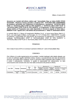
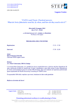
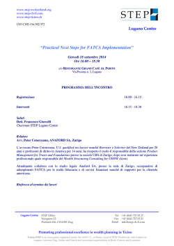
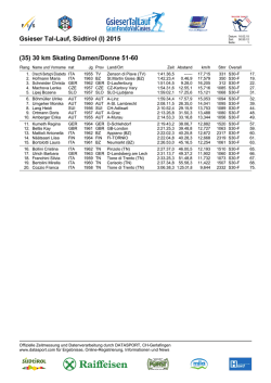
31100191
I376 I GB 0114
DCRL3 – DCRL5
DCRL3 – DCRL5
Regolatore automatico
del fattore di potenza
Automatic Power Factor
Controller
MANUALE DI INSTALLAZIONE
INSTALLATION MANUAL
ATTENZIONE!
Leggere attentamente il manuale prima dell’utilizzo e l’installazione.
Questi apparecchi devono essere installati da personale qualificato, nel
rispetto delle vigenti normative impiantistiche, allo scopo di evitare danni a
persone o cose.
Prima di qualsiasi intervento sullo strumento, togliere tensione dagli ingressi di misura e di
alimentazione e cortocircuitare i trasformatori di corrente.
Il costruttore non si assume responsabilità in merito alla sicurezza elettrica in caso di utilizzo
improprio del dispositivo.
I prodotti descritti in questo documento sono suscettibili in qualsiasi momento di evoluzioni o
di modifiche. Le descrizioni ed i dati a catalogo non possono pertanto avere alcun valore
contrattuale.
Un interruttore o disgiuntore va compreso nell’impianto elettrico dell’edificio. Esso deve
trovarsi in stretta vicinanza dell’apparecchio ed essere facilmente raggiungibile da parte
dell’operatore. Deve essere marchiato come il dispositivo di interruzione dell’apparecchio: IEC/
EN 61010-1 § 6.11.2.1.
Pulire lo strumento con panno morbido, non usare prodotti abrasivi, detergenti liquidi o
solventi.
WARNING!
x Carefully read the manual before the installation or use.
x This equipment is to be installed by qualified personnel, complying to
current standards, to avoid damages or safety hazards.
Before any maintenance operation on the device, remove all the voltages from measuring
and supply inputs and short-circuit the CT input terminals.
Products illustrated herein are subject to alteration and changes without prior notice.
Technical data and descriptions in the documentation are accurate, to the best of our
knowledge, but no liabilities for errors, omissions or contingencies arising there from are
accepted.
A circuit breaker must be included in the electrical installation of the building. It must be
installed close by the equipment and within easy reach of the operator.
It must be marked as the disconnecting device of the equipment:
IEC /EN 61010-1 § 6.11.2.1.
Clean the instrument with a soft dry cloth; do not use abrasives, liquid detergents or
solvents.
Introduzione
Introduction
Il regolatore automatico del fattore di potenza DCRL è stato progettato incorporando
lo stato dell’arte delle funzioni richieste per le applicazioni di rifasamento. Realizzato
con un contenitore dedicato, di dimensioni estremamente compatte, il DCRL unisce
il moderno design del frontale alla praticità di montaggio e alla possibilità di
espansione sul retro, dove è possibile alloggiare un modulo della serie EXP.... Il
display LCD consente una interfaccia utente chiara ed intuitiva.
The DCRL automatic power factor control unit has been designed to offer state-ofthe-art functions for power factor compensation applications. Built with dedicated
components and extremely compact, the DCRL combines the modern design of
the front panel with practical installation and the possibility of expansion from the
rear, where one EXP series module can be slotted. The LCD screen provides a
clear and intuitive user interface.
Descrizione
Description
x
x
x
x
x
x
x
x
x
x
x
x
x
x
x
x
x
x
x
x
Controllore automatico del fattore di potenza.
Montaggio a pannello, contenitore standard 96x96mm.
Display LCD retroilluminato.
Versioni:
o
DCRL3 con 3 gradini, espandibile a 5 max.
o
DCRL5 con 5 gradini, espandibile a 7 max.
4 tasti di navigazione per funzioni ed impostazioni.
Messaggi di allarme con testi in 6 lingue.
Bus di espansione con 1 slot per moduli di espansione serie EXP:
o Interfacce di comunicazione RS232, RS485, USB.
o
Uscite a relè aggiuntive
Elevata accuratezza delle misure in vero valore efficace (TRMS).
Vasta gamma di misure disponibili, inclusive di THD di tensione e di corrente
con analisi delle singole armoniche fino al 15.mo ordine.
Ingresso di misura tensione separato dalla alimentazione, utilizzabile con TV in
applicazioni di media tensione.
Alimentazione ausiliaria ad ampio range di tensione (100-440 VAC).
Interfaccia di programmazione ottica frontale, isolata galvanicamente, alta
velocità, impermeabile, compatibile con dongle USB e WiFi.
Protezione impostazioni via password a 2 livelli.
Copia di salvataggio delle impostazioni originali.
Sensore di temperatura incorporato.
Montaggio senza necessità di utensili.
Doc: MHIT200B1012.docx
x
x
x
x
x
x
x
x
x
x
x
x
Automatic power factor controller.
Flush-mount, standard 96x96mm housing.
Backlit LCD screen.
Versions:
o
DCRL3 with 3 relays, expandable to 5 max.
o
DCRL5 with 5 relays, expandable to 7 max.
4 navigation keys for function and settings.
Alarm messages in 6 languages.
Expansion bus with 1 slot for EXP series expansion modules:
o RS232, RS485, USB communications interface.
o Additional relay outputs.
High accuracy TRMS measurements.
Wide selection of electrical measures, including voltage and current THD with
harmonic analysis up to 15th order.
Voltage input separated from power supply, suitable for VT connection in
medium voltage applications.
Wide-range power supply (100-440VAC).
Front optical programming interface: galvanically isolated, high speed,
waterproof, USB and WiFi dongle compatible.
2-level password protection for settings.
Backup copy of original commissioning settings.
Built-in temperature sensor.
Tool-less panel mount.
20/01/2014
p. 1 / 8
Funzione dei tasti frontali
Front keyboard
Tasto MODE – Selezione a rotazione fra le misure disponibili. Usato anche per l’
accesso ai menu di programmazione.
Tasti e - Servono per impostare valori e selezionare gradini.
Tasto MAN-AUT- Serve per selezionare la modalità operativa fra manuale ed
automatico.
MODE Key - Used to select among available measurements. Used also to
access programming menus.
and keys - Used to set values and to select steps.
MAN-AUT key - Used to select operating mode between manual and automatic.
Indicazioni sul display
Display indications
Modo
Manuale
Induttivo /
capacitivo
Modo
Automatiico
Stato ventola
di
raffreddam.
Stato uscite
Manual
mode
Inductive /
capacitive
Automatic
mode
Cooling fan
status
Output status
Display
principale
Stato step
Main display
Step status
Barra grafica
Allarme
attivo
Bar graph
Active alarm
Display
secondario
Display
alfanumerico
Secondary
display
Alphanumeric
display
Modi operativi
Operating modes
Esistono tre possibili modi operativi, elencati di seguito:
There are three possible operating modes, listed below:
Modo TEST
TEST Mode
x Quando l’apparecchio é nuovo di fabbrica e non è mai stato programmato, entra
automaticamente nel modo TEST che consente all’installatore di attivare
manualmente le singole uscite a relè, in modo da poter verificare la correttezza
del cablaggio del quadro.
x Il modo TEST è evidenziato dalla presenza di tre trattini --- sul display principale.
x L’attivazione e la disattivazione delle uscite avviene direttamente premendo i
tasti e , ma senza considerare il tempo di riconnessione.
x La modalità TEST viene abbandonata automaticamente dopo aver effettuato la
programmazione dei parametri (vedere capitolo Impostazione dei parametri).
x When the unit is brand new and has never been programmed, it automatically
enters in TEST mode that allows the installer to manually activate the
individual relay outputs, so you can verify the correct wiring of the panel.
x The TEST mode is indicated by three dashes --- shown on the main display.
x The activation and deactivation of the outputs is done directly by pushing
and buttons, but without considering the reconnection time.
x The TEST mode is automatically left after the parameter programming is done
(see Parameter setting chapter).
Modi MAN e AUT
MAN and AUT Modes
x Le icone AUT e MAN indicano il modo di funzionamento automatico o manuale.
x Per cambiare modalità, premere il tasto MAN/AUT per 1 secondo consecutivo.
x La modalità di funzionamento rimane memorizzata anche in assenza della
tensione di alimentazione.
x The icons AUT and MAN indicate the operating mode automatic or manual.
x To change the mode, press the MAN / AUT button for 1 second in a row.
x The operating mode remains stored even after removing and reapplying the
power supply voltage.
Modo MAN
MAN Mode
x Quando l’apparecchio é in modalità manuale, é possibile selezionare uno degli
step ed inserirlo o disinserirlo manualmente.
x Oltre alla apposita icona, il display alfanumerico visualizza MAN per evidenziare
la modalità manuale. Premendo MODE è possibile scorrere le altre misure come
di consueto.
x Mentre il display alfanumerico à posizionato su MAN, è possibile
attivare/disattivare manualmente gli step. Per selezionare uno step utilizzare i
tasti o . Lo step selezionato lampeggia velocemente.
x Premere MODE per inserire o disinserire lo step selezionato.
x Se lo step selezionato non ha ancora esaurito il tempo di riconnessione, l’icona
MAN lampeggerà ad indicare che l’operazione é stata accettata e che verrà
eseguita non appena possibile.
x La configurazione manuale degli step viene mantenuta anche in assenza della
tensione di alimentazione. Quando l’apparecchio viene rialimentato, lo stato
originario dei gradini viene ripristinato.
x
Icona modo
MAN
Tot kvar
inseriti in
MAN
Seleziona step
MODE
x
x
x
x
x
When the unit is in manual mode, you can select one of the steps and
manually connected or disconnect it.
In addition to the specific icon, the alphanumeric display shows MAN in order to
highlight the manual mode condition. Press MODE to view the other
measurements as usual.
While the display shows MAN, it is possible to select the step to be switched on
or off. To select a step, use the or buttons. The selected step will flash
quickly.
Press MODE to activate or deactivate the selected step.
If the selected step has not yet exhausted the reconnection time, the MAN
icon will flash to indicate that the transaction has been accepted and will be
conducted as soon as possible.
Manual configuration of the steps is maintained even when the power supply
voltage is removed. When the power returns, the original state of the steps is
restored.
Step inseriti
MAN mode
icon
Connected
steps
Indicazione
selezione
manuale
Tot kvar
inserited in
MAN
Manual step
selection
enabled
Commuta stato step
Select step
MODE
Change step status
Modo AUT
AUT Mode
x In modalità automatico l’apparecchio calcola la configurazione di gradini ottimale
per raggiungere il cosM impostato.
x Il criterio di selezione tiene in considerazione molte variabili quali: la potenza dei
singoli gradini, il numero di manovre, il tempo totale di utilizzo, il tempo di
riconnessione, ecc.
x L’apparecchio evidenzia l’imminenza dell’inserzione o disinserzione dei gradini
con il lampeggio del loro numero identificativo. Il lampeggio potrebbe protrarsi
nei casi in cui l’inserimento di un gradino non è possibile a causa del tempo di
riconnessione (tempo di scarica del condensatore).
x In automatic mode, the controller calculates the optimum configuration of
capacitor steps in order to reach the set cos M.
x The selection criteria takes into account many variables such as: the power of
each step, the number of operations, the total time of use, the reconnection
time, etc.
x The controller displays the imminent connection or disconnection of the steps
with the flashing of their identification number (left). The flashing can last in
cases in which the insertion of a step is not possible due to the reconnection
time (discharge time of the capacitor).
Doc: MHIT200B1012.docx
20/01/2014
p. 2 / 8
Espandibilità
x Grazie al suo bus di espansione, la DCRL può essere espansa con un modulo
aggiuntivo della serie EXP….
module.
x Per inserire un modulo di espansione:
o
o
o
o
o
Expandability
x Thanks to expansion bus, the DCRL can be expanded with one EXP… series
x To insert an expansion module:
togliere l’alimentazione alla DCRL.
rimuovere il coperchio protettivo dello slot di espansione.
inserire il gancio superiore del modulo nella apposita feritoia in alto nello
slot .
ruotare il modulo verso il basso inserendo il connettore sul bus.
premere fino a che l’apposita clip sul lato inferiore del modulo si aggancia
a scatto.
x Quando una DCRL viene alimentata, riconosce automaticamente il modulo EXP
ad essa collegato.
x I moduli di espansione forniscono delle risorse aggiuntive che possono essere
sfruttate tramite gli opportuni menu di impostazione.
x I menu di impostazione che riguardano le espansioni sono disponibili anche se i
moduli non sono fisicamente presenti.
x La seguente tabella riassume i modelli di moduli di espansione supportati:
TIPO MODULO
CODICE
FUNZIONE
STEP AGGIUNTIVI
I/O DIGITALI
COMUNICAZIONE
EXP 10 06
EXP 10 03
EXP 10 10
EXP 10 11
EXP 10 12
2 STEP RELE’
2 RELE’ IN SCAMBIO
USB
RS-232
RS-485
o
o
o
o
o
remove the power supply to DCRL.
remove the protecting cover of the expansion slot.
insert the upper hook of the module into the fixing hole on the top of the
expansion slot.
rotate down the module body, inserting the connector on the bus.
push until the bottom clip snaps into its housing.
x When the DCRL is powered on, it automatically recognises the EXP module that
have been mounted.
x The expansion modules provide additional resources that can be used through
the dedicated setup menus.
x The setup menus related to the expansions are always accessible, even if the
expansion modules are not physically fitted.
x The following table indicates which models of expansion modules are supported:
MODULE TYPE
ADDITIONAL STEPS
DIGITAL I/O
COMMUNICATION
CODE
FUNCTION
EXP 10 06
EXP 10 03
EXP 10 10
EXP 10 11
EXP 10 12
2 STEP RELAYS
2 RELAY C/O
USB
RS-232
RS-485
Porta di programmazione IR
IR programming port
x La configurazione dei parametri della DCRL si può effettuare tramite la porta
ottica frontale, attraverso la chiavetta di programmazione IR-USB codice CX01
oppure la chiavetta IR-WiFi codice CX02.
x Semplicemente avvicinando una chiavetta CX.. alla porta frontale ed inserendo
le spine negli appositi fori, si otterrà il vicendevole riconoscimento dei dispositivi
evidenziato dal colore verde del LED LINK sulla chiavetta di programmazione.
x The parameters of the DCRL can be configured through the front optical port,
using the IR-USB code CX01 programming dongle, or with the IR-WiFi code
CX02 dongle.
x Simply hold the CX.. dongle up to the front panel, connecting the plugs to the
relevant connectors, and the device will be acknowledged as shown by the
LINK LED on the programming dongle flashing green.
Adattatore di programmazione WiFi cod. CX02
WiFi programming dongle code CX02
Adattatore di programmazione USB cod. CX01
USB programming dongle code CX01
Impostazione parametri da PC
Parameter setting with PC
x Mediante il software di set-up DCRG Remote control è possibile effettuare il
trasferimento dei parametri di set-up (precedentemente impostati) da DCRL al
disco del PC e viceversa.
x You can use the DCRG Remote control software to transfer (previously
programmed) set-up parameters from the DCRL to the hard drive of the PC and
vice versa.
Impostazione dei parametri (setup) dal pannello frontale
Parameter setting (setup) from front panel
Per accedere al menu di programmazione (setup):
x Per accedere alla impostazione la centralina si deve trovare in modalità TEST
(prima impostazione) oppure in modalità MAN.
x Dalla normale visualizzazione misure, premere MODE per 3 secondi per
richiamare il menu principale. Compare SET sul display principale.
x Se è stata impostata la password (P.21=ON), invece di SET compare PAS
(richiesta immissione password). Impostare la password numerica con e
To access the programming menu (setup) :
x To enter parameter programming the unit must be in TEST mode (first
programming) or in MAN mode.
x From the normal measurement display, press MODE for 3 seconds to recall the
main menu. SET is displayed on the main display.
x If you have set the password (P.21 = ON) instead of SET the display shows PAS
(password entry request). Set the numeric password using and then
Doc: MHIT200B1012.docx
20/01/2014
p. 3 / 8
poi premere MAN-AUT per confermare.
x Se la password è corretta verrà visualizzato OK U oppure OK A a seconda se la
x
x
x
x
password è di livello utente o avanzato. Le password si definiscono con P.22 e
P.23. Di default sono impostate a 001 e 002.
Se si inserisce una password errata verrà visualizzato ERR.
Dopo l’inserimento della password l’accesso è consentito fino a che
l’apparecchio non vine resettato o fino a che non trascorrono 2 minuti senza
pressioni sui tasti.
Una volta inserita la password, ripetere la procedura di accesso alle
impostazioni.
Premere per selezionare il sottomenu desiderato (BASÆ ADVÆ ALA…)
che viene visualizzato sul display alfanumerico.
x Nella seguente tabella sono elencati i sottomenu disponibili:
Cod
BAS
ADV
ALA
CMD
CUS
SAVE
EXIT
Descrizione
Accesso al menu Base
Accesso al menu Avanzato
Accesso al menu Allarmi
Accesso al menu Comandi
Accesso al menu Custom
Uscita con salvataggio delle modifiche
Uscita senza salvataggio (annulla)
x Premere MAN-AUT per accedere al sottomenu selezionato.
x Quando si è all’interno di un sottomenu, sul display principale viene visualizzato
press MAN-AUT to confirm.
x If the password is correct the unit will show OK U or OK A depending on the
x
x
x
x
x
entered password is user or the advanced level. The password can be defined
with parameters P.22 and P.23. Factory default is 001 and 002 respectively.
If the entered password is wrong the unit will show ERR.
After having entered the password, tha access is enabled until the unit is reinitialized or for 2 minutes without pressing any key.
After having entered the password, repeat the procedure to access the
parameter setting.
Press to select the desired submenu (BASÆ ADV Æ ALA ... ) that is
shown on the alphanumeric display.
The following table lists the available submenus:
Cod
BAS
ADV
ALA
CMD
CUS
SAVE
EXIT
Description
Access to Base menu
Accesso to Advanced menu
Accesso to Alarm menu
Access to Command menu
Access to Custom menu
Exits saving modifications.
Exits without saving (cancel)
x Press MAN- AUT to access the submenu.
x When you are in a submenu, the main display shows the code of the selected
il codice del parametro selezionato (es. P.01), mentre sui display numerico ed
alfanumerico in basso vengono visualizzati i valori del parametro e/o la
descrizione.
x Premere MAN-AUT per avanzare nella selezione delle voci (ad esempio
scorrere fra i parametri P.01ÆP.02Æ P.03…), oppure premere MODE per
retrocedere.
x Mentre una parametro è selezionato, con se ne può impostare il valore.
parameter (eg P.01 ), while the numeric/alphanumeric displays at the bottom of
the screen showsthe parameter value and / or description.
x Press MAN- AUT to advance in the selection of items (such as scroll through
parameters P.01 Æ P02 Æ P03… ), or press MODE to go back to the previous
parameter.
x While a parameter is selected, with you can increase/decrease its value.
x Una volta raggiunta l’ultimo parametro del menu, premendo ancora MAN-AUT si
x Once you reach the last parameter of the menu, by pressing MAN- AUT once
ritorna alla selezione dei sottomenu.
x Con selezionare SAVE per salvare le modifiche o EXIT per annullare.
x Using select SAVE to save the changes or EXIT to cancel.
x In alternativa, dall’interno della programmazione, tenendo premuto MAN-AUT
x Alternatively, from within the programming, holding MAN- AUT for three
per tre secondi, si salvano le modifiche e si esce direttamente.
x Se non vengono premuti tasti per 2 minuti consecutivi, il menu setup viene
abbandonato automaticamente e il sistema torna alla visualizzazione normale
senza salvare i parametri (come con EXIT).
x Rammentiamo che, per i soli dati di set-up modificabili da tastiera, è possibile
fare una copia di sicurezza (backup) nella memoria eeprom della DCRL. Questi
stessi dati all’occorrenza possono essere ripristinati (restore) nella memoria di
lavoro. I comandi di copia di sicurezza e ripristino dei dati sono disponibili nel
Menu comandi.
Doc: MHIT200B1012.docx
more will return you to the submenu selection.
seconds will save the changes and exit directly.
x If the user does not press any key for more than 2 minutes, the system leaves
the setup automatically and goes back to normal viewing without saving the
changes done on parameters (like EXIT).
x N.B.: a backup copy of the setup data (settings that can be modified using the
keyboard) can be saved in the eeprom memory of the DCRL. This data can be
restored when necessary in the work memory. The data backup 'copy' and
'restore' commands can be found in the Commands menu.
20/01/2014
p. 4 / 8
Tabella dei parametri
x Di seguito vengono riportati tutti i parametri di programmazione disponibili in forma
Parameter table
x Below are listed all the programming parameters in tabular form. For each parameter
tabellare. Per ogni parametro sono indicati il range di impostazione possibile ed il
default di fabbrica, oltre ad una spiegazione della funzionalità del parametro. La
descrizione del parametro visibile sul display può in qualche caso differire da
quanto riportato in tabella a causa del ridotto numero di caratteri disponibile. Il
codice del parametro vale comunque come riferimento.
x Nota: i parametri evidenziati nella tabella con uno sfondo ombreggiato sono
essenziali al funzionamento dell’impianto, rappresentano quindi la
programmazione minima indispensabile per la messa in funzione.
are indicated the possible setting range and factory default, as well as a brief
explanation of the function of the parameter. The description of the parameter shown
on the display can in some cases be different from what is reported in the table
because of the reduced number of characters available. The parameter code can be
used however as a reference.
x Note: the parameters shown in the table with a shaded background are essential to
the operation of the system, thus they represent the minimum programming required
for operation.
MENU BASE
BASE MENU
COD
P.01
P.02
P.03
DESCRIZIONE
Primario TA
Secondario TA
Fase lettura correnti TA
ACC UdM
Usr
A
Usr
A
Usr
DEF
OFF
5
L3
P.04
Verso collegamento TA
Usr
Aut
P.05
Fase lettura tensioni
Usr
L1-L2
P.06
P.07
P.08
Potenza step più piccolo
Frequenza nominale
Usr
Usr
Usr
Kvar
V
Hz
1.00
400V
Aut
P.09
P.10
P.11
Tempo di riconnessione
Sensibilità
Funzione step 1
Adv
Usr
Usr
sec
sec
60
60
OFF
P.12
P.13
P.14
P.15
P.16
P.17
P.19
Funzione step 2
Funzione step 3
Funzione step 4
Funzione step 5
Funzione step 6
Funzione step 7
Setpoint cosfi
Usr
Usr
Usr
Usr
Usr
Usr
Usr
Tensione nom. condensatori
OFF
OFF
OFF
OFF
OFF
OFF
0.95
IND
ENG
RANGE
OFF / 1...10.000
1/5
L1
L2
L3
Aut
Dir
Inv
L1-L2
L2-L3
L3-L1
L1-N
L2-N
L3-N
0.10 ... 10000
50 ... 50000
Aut
50Hz
60Hz
Var
1 … 30000
1 … 1000
OFF
1…32
ON
NOA
NCA
FAN
MAN
AUT
A01…A13
=
=
=
=
=
=
0.50 Ind – 0.50 Cap
ENG
ITA
FRA
SPA
POR
DEU
P.01 – Valore del primario dei trasformatori di corrente. Esempio: con TA 800/5 impostare 800.
Se impostato su OFF, alla messa in tensione l’apparecchio richieerà di impostare il TA e
permetterà l’accesso diretto a questo parametro.
P.02 – Valore del secondario dei trasformatori di corrente. Esempio: con TA 800/5 impostare 5.
P.03 – Definisce su quale fase l’apparecchio legge il segnale di corrente. Il collegamento degli
ingressi amperometrici deve coincidere con quanto impostato in questo parametro. Sono
supportate tutte le combinazioni con il parametro P.05.
P.04 – Lettura della polarità di collegamento dei TA.
AUT = La polarità è riconosciuta automaticamente alla messa in tensione. Utilizzabile solo
quando l’impianto non ha alcun dispositivo generatore.
Dir = Riconoscimento automatico disabilitato. Collegamento diretto.
Inv = Riconoscimento automatico disabilitato. Collegamento inverso (incrociato).
P.05 – Definisce su quali fasi l’apparecchio legge il segnale di tensione. Il collegamento degli
ingressi voltmetrici deve coincidere con quanto impostato in questo parametro. Sono
supportate tutte le combinazioni con il parametro P.03.
P.06 – Valore in kvar dello step più piccolo installato (equivalente al peso 1). Potenza di targa
del banco di condensatori erogato alla tensione di targa specificata in P.07 e riferito al totale
dei tre condensatori se in applicazione trifase.
P.07 – Tensione nominale di targa dei condensatori, alla quale viene erogata la potenza
specificata in P.06. Se i condensatori sono utilizzati ad un tensione diversa (inferiore) rispetto a
quella nominale, la potenza risultante viene ricalcolata automaticamente dall’apparecchio.
P.08 – Frequenza di lavoro dell’impianto:
Aut = selezione automatica fra 50 e 60 Hz alla messa in tensione
50 Hz = fissa a 50 Hz
60 Hz = fissa a 60 Hz
Var = variabile, misurata continuamente ed adattata.
P.20
Lingua messaggi di
allarme
Usr
Doc: MHIT200B1012.docx
COD
P.01
P.02
P.03
DESCRIPTION
CT primary
CT secondary
CT read phase
ACC UoM
Usr
A
Usr
A
Usr
DEF
OFF
5
L3
P.04
CT wiring polarity
Usr
Aut
P.05
Voltage read phase
Usr
L1-L2
P.06
P.07
P.08
Smallest step power
Rated capacitor voltage
Nominal frequency
Usr
Usr
Usr
Kvar
V
Hz
1.00
400V
Aut
P.09
P.10
P.11
Reconnection time
Sensitivity
Step 1 function
Adv
Usr
Usr
sec
sec
60
60
OFF
P.12
P.13
P.14
P.15
P.16
P.17
P.19
Step 2 function
Step 3 function
Step 4 function
Step 5 function
Step 6 function
Step 7 function
Cos-phi setpoint
Usr
Usr
Usr
Usr
Usr
Usr
Usr
OFF
OFF
OFF
OFF
OFF
OFF
0.95
IND
ENG
RANGE
OFF / 1...10.000
1/5
L1
L2
L3
Aut
Dir
Inv
L1-L2
L2-L3
L3-L1
L1-N
L2-N
L3-N
0.10 ... 10000
50 ... 50000
Aut
50Hz
60Hz
Var
1 … 30000
1 … 1000
OFF
1…32
ON
NOA
NCA
FAN
MAN
AUT
A01…A13
=
=
=
=
=
=
0.50 Ind – 0.50 Cap
ENG
ITA
FRA
SPA
POR
DEU
P.01 - The value of the primary current transformer. Example: with CT 800/5 set 800. If set to
OFF, after the power-up the device will prompt you to set the CT and allow direct access to this
parameter.
P.02 - Value of the secondary of the current transformers. Example: with CT 800/5 set 5.
P.03 – It defines on which phase the device reads the current signal. The wiring of current
inputs must match the value set for this parameter. Supports all possible combinations of
parameter P.05.
P.04 - Reading the connection polarity of the CT.
AUT = Polarity is automatically detected at power up. Can only be used when working with only
one CT and when the system has no generator device.
Dir = Automatic detection disabled. Direct connection.
Inv = Automatic detection disabled. Reverse wiring (crossover).
P.05 - Defines on which and on how many phases the device reads the voltage signal. The
wiring of voltage inputs must match the setting for this parameter. Supports all possible
combinations of parameter P.03.
P.06 - Value in kvar of the smallest step installed (equivalent to the step weight 1). Rated
power of the capacitor bank provided at the rated voltage specified in P.07 and referred to the
total of the three capacitors for three-phase applications.
P.07 - Rated plate capacitor, which is delivered in specified power P.06. If the capacitors are
used to a voltage different (lower) than nominal, the resulting power is automatically
recalculated by the device.
P.08 - Working frequency of the system:
Aut = automatic selection between 50 and 60 Hz at power on.
50Hz = fixed to 50 Hz.
60Hz = fixed to 60 Hz.
Var = variable, measured continuously and adjusted.
P.20
Alarm messages language
20/01/2014
Usr
p. 5 / 8
P.09 – Tempo minimo che deve trascorrere fra la disconnessione di uno step e la successiva
riconnessione sia in MAN che in AUT. Durante questo tempo il numero dello step sulla pagina
principale lampeggia.
P.10– Sensibilità alla connessione. Parametro che imposta la velocità di reazione della
centralina. Con valori bassi di P.10 la regolazione è veloce (maggior precisione intorno al
setpoint ma maggior numero di manovre). Con valori alti invece si hanno reazioni più lente
della regolazione, con minor numero di manovre degli step. Il tempo di ritardo alla reazione è
inversamente proporzionale alla richiesta di step per raggiungere il setpoint: tempo attesa =
(sensibilità / numero di step richiesti).
Esempio: impostando la sensibilità a 60s, se viene richiesta l’inserzione di uno step di peso 1
vengono attesi 60s (60/1 = 60) . Se invece servono un totale di 4 step verranno attesi 15s (60 /
4 = 15).
P.11 … P18 – Funzione dei relè di uscita 1…8:
OFF = Non utilizzato
1..32 = Peso dello step. A questo relè è collegato un banco di condenstaori di
potenza n volte (n=1…32) quella del più piccolo, definita con P.06.
ON = Sempre attivato.
NOA = Allarme normalmente disecctato. Il relè si eccita in presenza di un qualsiasi
allarme con la proprietà Allarme globale attiva.
NCA = Allarme normalmente eccitato. Il relè si diseccita in presenza di un qualsiasi
allarme con la proprietà Allarme globale attiva.
FAN = Relè controlla la ventola di raffreddamento.
MAN = Relè eccitato quando centralina è in MAN.
AUT = Relè eccitato quando centralina è in AUT.
A01…A13 = Il relè si eccita in presenza dell’allarme specificato.
P.19 – Setpoint (valore da raggiungere) del cosfi. Utilizato in applicazioni standard.
P.20 - Lingua dei messaggi di allarme scorrevoli.
P.09 - Minimum time that must elapse between the disconnection of one step and the
subsequent reconnection both in MAN or AUT mode. During this time the number of the step
on the main page is blinking.
P.10 - Connection sensitivity. This parameter sets the speed of reaction of the controller. With
small values of P.10 the regulation is fast (more accurate around the setpoint but with more
step swithchings). With high values instead we’ll have slower reactions of the regulation, with
fewer switchings of the steps. The delay time of the reaction is inversely proportional to the
request of steps to reach the setpoint: waiting time = (sensitivity / number of steps required).
Example: setting the sensitivity to 60s, if you request the insertion of one step of weight 1 are
expected 60s (60/1 = 60). If instead serve a total of 4 steps will be expected 15s (60/4 = 15).
P11 ... P18 - Function of output relays 1 ... 8:
OFF = Not used .
1 .. 32 = Weight of the step. This relay drives a bank of cpacitors which power is n
times (n = 1…32) the smallest power defined with parameter P.06.
ON = Always on.
NOA = Alarm normally de-energized. The relay is energized when any alarm with the
Global alarm property arises.
NCA = Alarm normally energized. The relay is de-energized when any alarm with the
Global alarm property arises.
FAN = The relay controls the cooling fan.
MAN = Relay is energized when device is in MAN mode.
AUT = Relay is energized when device is in AUT mode.
A01 ... A13 = The relay is energized when the alarm specified is active.
P.19 - Setpoint (target value) of the cosphi. Used for standard applications.
P.20 - Language of scrolling alarm messages.
.
NOTE: Per i successivi menù vedi manuale completo
scaricabile dal sito
NOTE: For the other menus, refer to the complete instructions
manual available on the website.
Sottocompensazione
Sovracompensazione
Corrente impianto troppo bassa
Corrente impianto troppo alta
Tensione impianto troppo bassa
Tensione impianto troppo alta
Sovraccarico corrente condensatori
Temperatura troppo alta
Microinterruzione
THD tensione troppo alto
THD corrente impianto troppo alto
Richiesta manutenzione
Step difettoso
15 min
120 s
5s
120 s
5s
15 min
180 s
30 s
0s
120 s
120 s
0s
15 min
Installazione
x DCRL è destinata al montaggio da incasso. Con il corretto montaggio garantisce
una protezione frontale IP54.
x Dall’interno del quadro, per ciascuna delle quattro clips di fissaggio, posizionare la
clip in una delle due guide laterali, premendo successivamente sullo spigolo della
clip in modo da agganciare a scatto anche la seconda guida.
x Spingere la clip in avanti facendo pressione sulle sue pareti laterali e facendole
scorrere sulle guide fino che le apposite alette deformabili premono al massimo
possibile contro la superficie interna del pannello
Doc: MHIT200B1012.docx
A01
A02
A03
A04
A05
A06
A07
A08
A09
A10
A11
A12
A13
Delay
Disconnection
Undercompensation
Overcompensation
Current too low
Current too high
Voltage too low
Voltage too high
Capacitor current overload
Temperature too high
No-Voltage release
Voltage THD too high
Current THD too high
Maintenance requested
Step failure
Alarm relay
Cod.
Description
Enable
A01
A02
A03
A04
A05
A06
A07
A08
A09
A10
A11
A12
A13
Descrizione
Ritardo interv.
Default alarm properties
Disconness.
Proprietà di default allarmi
Relè allarme
x When an alarm is generated , the display will show an alarm icon, the code and the
description of the alarm in the language selected.
x If the navigation keys in the pages are pressed, the scrolling message showing the
alarm indications will disappear momentarily, to reappear again after 30 seconds.
x Alarms are automatically resetted as soon as the alarm conditions that have
generated them disappear.
x In the case of one or more alarms, the behaviour of the DCRL depends on the
properties settings of the active alarms.
Abilitazione
Alarms
x Al sorgere di un allarme, il display mostra una icona di allarme, un codice
identificativo e la descrizione dell’allarme nella lingua selezionata.
x Se vengono premuti i tasti di navigazione delle pagine, la scritta scorrevole con le
indicazioni di allarme scompare per poi ricomparire dopo 30 secondi.
x Il reset degli allarmi è automatico quando scompaiono le condizioni che li hanno
generati.
x In seguito al verificarsi di uno o più allarmi, la DCRL ha un comportamento
dipendente dalla impostazione delle proprietà degli allarmi attivi.
Cod.
Allarmi
15 min
120 s
5s
120 s
5s
15 min
180 s
30 s
0s
120 s
120 s
0s
15 min
Installation
x DCRL is designed for flush-mount installation. With proper mounting, it guarantees
IP54 front protection.
x From inside the panel, for each four of the fixing clips, position the clip in one of the
two sliding guide, then press on the clip corner until the second guide snaps in.
x Push the clip forward pressing on its side and making it slide on the guides until it
presses completely on the internal surface of the panel.
20/01/2014
p. 6 / 8
x Per i collegamenti elettrici fare riferimento agli schemi di connessione riportati
nell’apposito capitolo e alle prescrizioni riportate nella tabella delle caratteristiche
tecniche.
Schemi di collegamento
x For the electrical connection see the wiring diagrams in the dedicated chapter and
the requirements reported in the technical characteristics table.
Wiring diagrams
ATTENZIONE!!
WARNING!
Togliere sempre tensione quando si opera sui morsetti.
Inserzione trifase standard
Disconnect the line and the supply when operating on terminals.
Standard Three-phase wiring
NOTES
NOTE
x Per inserzione trifase, l’ingresso voltmetrico deve essere connesso tra due fasi; il T.A. di
linea deve essere inserito sulla rimanente fase.
x La polarità dell’ingresso amperometrico è ininfluente.
Disposizione morsetti
x For three-phase connection, the voltage input must be connected phase to phase; the current transformer
must be connected on the remaining phase.
x The polarity of the current/voltage input is indifferent,
Terminals position
13
12
3
11
10
1
Aux supply
9
8
2
100-440V~
50/60Hz
3,5 W
9,5 VA
2
7
3
4
1
V Input
6
100-600V~
50/60Hz
COM
MAX
10A
Dimensioni meccaniche e foratura pannello (mm)
Doc: MHIT200B1012.docx
5
S1
14
S2
13
12
5
11
10
4
1
Aux supply
2
100-440V~
50/60Hz
3,5 W
9,5 VA
9
3
8
2
7
3
4
1
V Input
6
100-600V~
50/60Hz
COM
MAX
10A
B300 / 250V~ 5A AC1 / 1,5A 440V~ AC15 (NO CONTACT)
14
S2
Current 0,025-5A~
S1
B300 / 250V~ 5A AC1 / 1,5A 440V~ AC15 (NO CONTACT)
DCRL5
Current 0,025-5A~
DCRL3
5
Mechanical dimensions and front panel cutout (mm)
20/01/2014
p. 7 / 8
Caratteristiche tecniche
Technical characteristics
Alimentazione
Tensione nominale Us n
100 - 440V~
110 - 250V=
90 - 484V~
93,5 - 300V=
45 - 66Hz
3,5W – 9,5VA
>= 8ms
<= 25ms
F1A (rapidi)
Limiti di funzionamento
Frequenza
Potenza assorbita/dissipata
Rilascio relè alla micronterruzione
Tempo di immunità alla microinterruzione
Fusibili raccomandati
Ingresso voltmetrico
Tensione nominale Ue max
Campo di misura
Campo di frequenza
Tipo di misura
Impedenza dell’ingresso di misura
Modalità di collegamento
Accuratezza misura
Fusibili raccomandati
Ingressi amperometrici
Corrente nominale Ie
Campo di misura
Tipo di ingresso
Tipo di misura
Limite termico permanente
Limite termico di breve durata
Accuratezza misura
Autoconsumo
Precisione misure
Tensione di linea
Uscite a relè: DCRL3 OUT 1 - 2 / DCRL5 OUT 1 - 4
Tipo di contatto
DCRL3
DCRL5
Dati d’impiego UL
Massima tensione d’impiego
Portata nominale
Corrente massima al terminale comune dei contatti
Durata meccanica / elettrica
Uscite a relè: DCRL3 OUT 3 / DCRL5 OUT 5
Tipo di contatto
Dati d’impiego UL
Massima tensione d’impiego
Portata nominale
Durata meccanica / elettrica
Tensione di isolamento
Tensione nominale d’isolamento Ui
Tensione nomi. di tenuta a impulso Uimp
Tensione di tenuta a frequenza d’esercizio
Condizioni ambientali di funzionamento
Temperatura d’impiego
Temperatura di stoccaggio
Umidità relativa
Inquinamento ambiente massimo
Categoria di sovratensione
Categoria di misura
Sequenza climatica
Resistenza agli urti
Resistenza alle vibrazioni
Connessioni
Tipo di morsetti
Sezione conduttori (min e max)
Dati d’impiego UL
Sezione conduttori (min e max)
Coppia di serraggio
Contenitore
Esecuzione
Materiale
Grado di protezione frontale
Peso
Omologazioni e conformità
cULus
Conformità a norme
UL « Marking »
600VAC L-L (346VAC L-N)
50…720V L-L (415VAC L-N)
45…65Hz
Vero valore efficace (TRMS)
> 0.55M: L-N
> 1,10M: L-L
Linea monofase, bifase, trifase con o senza
neutro e trifase bilanciato
±1% ±0,5 digit
F1A (rapidi)
1A~ o 5A~
Per scala 5A: 0,025 - 6A~
Per scala 1A: 0,025 – 1,2A~
Shunt alimentati mediante trasformatore di
corrente esterno (bassa tensione) 5A max.
Vero valore efficace (RMS)
+20% Ie
50A per 1 secondo
± 1% (0,1…1,2In) ±0,5 digit
0,6VA
r0,5% f.s. r1digit
2 x 1 NO + comune contatti
4 x 1 NO + comune contatti
B300
30V= 1A Servizio ausiliario
440V~
AC1-5A 250V~ AC15-1,5A 440V~ (solo NO)
10A
1x10⁷ / 1x10⁵ operazioni
1 contatto scambio
B300 / 30V= 1A servizio ausiliario
440V~
AC1-5A 250V~ AC15-1,5A 440V~ (solo NO)
1x10⁷ / 1x10⁵ operazioni
600V~
9,5kV
5,2kV
-20 - +60°C
-30 - +80°C
80% (IEC/EN 60068-2-78)
Grado 2
3
III
Z/ABDM (IEC/EN 60068-2-61)
15g (IEC/EN 60068-2-27)
0.7g (IEC/EN 60068-2-6)
Estraibili
0,2...2,5 mmq (24y12 AWG)
0,75...2.5 mm² (18-12 AWG)
0,56 Nm (5 LBin)
Da incasso
Policarbonato
IP54 sul fronte – IP20 sui morsetti
320g
In corso
IEC/EN 61010-1, IEC/EN 61000-6-2
IEC/ EN 61000-6-4 UL508 e CSA C22.2-N°14
Use 60°C/75°C copper (CU) conductor only
AWG Range: 18 - 12 AWG stranded or solid
Field Wiring Terminals Tightening Torque:
4.5lb.in
Flat panel mounting on a Type 1 enclosure
n Alimentazione ausiliaria prelevata da un sistema con tensione fase-neutro 300V
Cronologia revisioni manuale
Rev
Data
00
20/01/2014
Note
x
Prima versione
Doc: MHIT200B1012.docx
Supply
Rated voltage Us n
100 - 440V~
110 - 250V=
90 - 484V~
93,5 - 300V=
45 - 66Hz
3.5W – 9.5VA
>= 8ms
<= 25ms
F1A (fast)
Operating voltage range
Frequency
Power consumption/dissipation
No-voltage release
Immunity time for microbreakings
Recommended fuses
Voltage inputs
Maximum rated voltage Ue
Measuring range
Frequency range
Measuring method
Measuring input impedance
600VAC L-L (346VAC L-N)
50…720V L-L (415VAC L-N)
45…65Hz
True RMS
> 0.55M: L-N
> 1,10M: L-L
Single-phase, two-phase, three-phase with or
without neutral or balanced three-phase system.
Wiring mode
Accuracy of measurement
Recommended fuses
Current inputs
Rated current Ie
Measuring range
1% ±0,5 digit
F1A (fast)
1A~ or 5A~
For 5A scale: 0.025 - 6A~
For 1A scale: 0.025 – 1.2A~
Shunt supplied by an external current
transformer (low voltage). Max. 5A
True RMS
+20% Ie
50A for 1 second
± 1% (0,1…1,2In) ±0,5 digit
0.6VA
Type of input
Measuring method
Overload capacity
Overload peak
Accuracy of measurement
Power consumption
Measuring accuracy
Line voltage
Relay output: DCRL3 OUT 1 - 2 / DCRL5 OUT 1 - 4
Contact type
DCRL3
DCRL5
UL Rating
r0.5% f.s. r1digit
2 x 1 NO + contact common
4 x 1 NO + contact common
B300
30V= 1A Pilot Duty
440V~
AC1-5A 250V~ AC15-1,5A 440V~ (NO only)
10A
1x10⁷ / 1x10⁵ ops
Max rated voltage
Rated current
Maximum current at contact common
Mechanical / electrical endurance
Relay output: DCRL3 OUT 3 / DCRL5 OUT 5
Contact type
1 changeover
UL Rating
B300 / 30V= 1A pilot duty
Max rated voltage
440V~
Rated current
AC1-5A 250V~ AC15-1,5A 440V~ (NO only)
Mechanical / electrical endurance
1x10⁷ / 1x10⁵ ops
Insulation voltage
Rated insulation voltage Ui
600V~
Rated impulse withstand voltage Uimp
9.5kV
Power frequency withstand voltage
5,2kV
Ambient operating conditions
Operating temperature
-20 - +60°C
Storage temperature
-30 - +80°C
Relative humidity
80% (IEC/EN 60068-2-78)
Maximum pollution degree
2
Overvoltage category
3
Measurement category
III
Climatic sequence
Z/ABDM (IEC/EN 60068-2-61)
Shock resistance
15g (IEC/EN 60068-2-27)
Vibration resistance
0.7g (IEC/EN 60068-2-6)
Connections
Terminal type
Plug-in / removable
Cable cross section (min… max)
0.2…2.5 mm² (24…12 AWG)
UL Rating
0,75…2.5 mm² (18…12 AWG)
Cable cross section (min… max)
Tightening torque
0.56 Nm (5 LBin)
Housing
Version
Flush mount
Material
Polycarbonate
Degree of protection
IP54 on front - IP20 terminals
Weight
320g
Certifications and compliance
cULus
Pending
IEC/EN 61010-1, IEC/EN 61000-6-2
Reference standards
IEC/ EN 61000-6-3 UL508 and CSA C22.2-N°14
UL Marking
Use 60°C/75°C copper (CU) conductor only
AWG Range: 18 - 12 AWG stranded or solid
Field Wiring Terminals Tightening Torque:
4.5lb.in
Flat panel mounting on a Type 1 enclosure
n Auxiliary supply connected to a line with a phase-neutral voltage 300V
Manual revision history
Rev
Date
00
20/01/2014
20/01/2014
Notes
x
First release
p. 8 / 8
© Copyright 2026 Paperzz