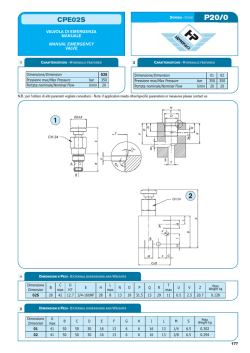
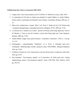
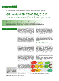
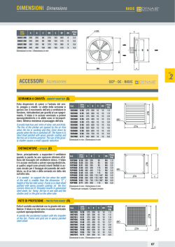
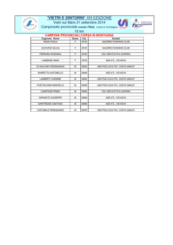
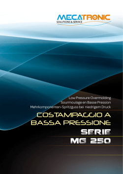
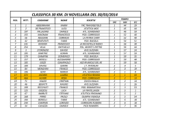
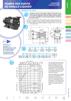
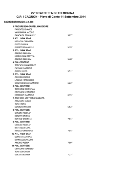
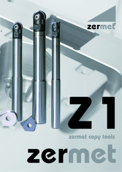
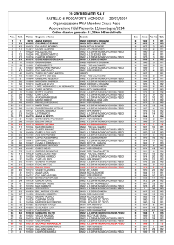
DUCT-BD
Ventilatore assiale intubato a trasmissione
Belt driven axial fan
APPLICAZIONI
APPLICATIONS
La serie DUCT-BD è stata progettata per tutte le applicazioni
nelle quali è necessario tenere il motore fuori dal flusso dell'aria ricca di
fumi, polveri e umidità.
La temperatura, dell'aria convogliata, massima ammessa
è di 60°C in servizio continuo. Le prestazioni sono corrispondenti
a quelle della serie DUCT-M con una riduzione del 5% in portata.
DUCT-BD line has been designed for all applications where
it is necessary to keep the motor outside the airflow, because of
smoke, dusts and humidity.
The maximun admitted temperature of the conveyed air is 60°C in
continuous service.
Performances correspond to those of DUCT-M line with a reduction
of 5% in capacity.
GAMMA
RANGE
La serie è costituita da 7 grandezze dal diametro 500 al 1000.
This line consists of 7 sizes with impeller diameter from
500 up to 1000 mm.
COSTRUZIONE
Convogliatore in lamiera d’acciaio protetto con verniciatura
epoxy.
Flange dimensionate a norma UNI ISO 6580.
CONSTRUCTION
Casing in steel sheet epoxy painted. Fixing flanges
according to UNI-ISO 6580 EUROVENT 1-2.
High efficiency impeller with airfoil blades in plastic material
and hub in die-cast aluminum alloy, variable pitch angle in still
position.
Balancing according to UNI ISO 1940.
Asynchronous three phase or single phase electric motor,
mounting type B3, protection IP 55, Class F insulated, service
S1, construction according to IEC/EEC (UNEL MEC) standards.
Monobloc assembled with free maintenance ball bearings.
Arrangement 9 (belt driven with impeller in throw position and
motor supported by the casing in position O)
Girante ad alto rendimento con pale a profilo alare, ad angolo
di calettamento variabile da fermo in tecnopolimero e mozzo
in fusione d’alluminio. Equilibratura secondo norme UNI ISO
1940.
Motore elettrico asincrono a corrente alternata, trifase o
monofase, forma B3, protezione IP 55, isolamento classe F,
servizio S1 costruzione conforme alle norme IEC/EEC (UNEL MEC).
Monoblocco montato con cuscinetti a sfera esenti manutenzione.
Esecuzione 9 (accoppiamento a cinghie con girante a sbalzo
e motore sostenuto dalla cassa in posizione 0)
TECHNICAL SPECIFICATIONS
SPECIFICHE TECNICHE
DUCT-BD standard
Conveyed air: clean or slightly dusty, not abrasive.
Temperature of conveyed air: -20°C / +60°C.
Voltage:
Three phase version (T) 400V-3Ph.-50Hz
single phase version (M) 230V-1Ph-50Hz.
Airflow from monobloc to impeller position A (FMG)..
DUCT-BD standard
Aria convogliata: pulita o leggermente polverosa, non abrasiva.
Temperatura aria convogliata: -20°C / +60°C.
Tensione d’alimentazione:
versione trifase (T) 400V-3Ph-50Hz.
versione monofase (M) 230V-1Ph-50Hz.
ACCESSORIES
Flusso dell'aria da monoblocco a girante, posizione A (FMG).
Same as DUCT-M series.
ACCESSORI
ON REQUEST
Gli stessi della serie DUCT-M.
Die- cast aluminum blades.
A RICHIESTA
Giranti completamente in alluminio.
55
DUCT-BD
Dimensioni
Dimensions
ØD
ØA
B
50
56
63
71
80
90
100
510
570
640
710
810
910
1010
450
450
500
600
600
700
800
G
Model
ØA
n° E Ø F
ØC
ØD
560 595
620 655
690 725
770 805
860 900
970 1010
1070 1110
n° E
ØF
12
12
12
16
16
16
16
12
12
12
12
12
16
16
Dimensioni in mm/Dimensions in mm
B
ØC
4
6
9
2
1
9
5
3
1 - Girante/Impeller
2 - Monoblocco/Monoblock
3 - Convogliatore/Casing
4 - Motore/Motor
5 - Puleggia condotta/Driven pulley
6 - Puleggia conduttrice/Driving pulley
7 - Cinghia/Belt
8 - Pannelli di protezione/Protection carters
9 - Rete di protezione (accessorio) - Obbligatorio per l’utilizzo a bocca libera
Protection grid (accessory) mandatory for free air
56
7
8
SIL SILP
Silenziatori circolari
Circular silencers
SIL-DU
SILP-DU
SILENZIATORI CIRCOLARI SIL-DU/SILP-DU
CIRCULAR SILENCERS SIL-DU/SILP-DU
I silenziatori cilindrici SIL-DU sono disponibili in due versioni, senza ogiva (SIL) e con
ogiva (SILP), la presenza dell’ogiva permette una maggiore attenuazione della
rumorosità ma genera una perdita di carico nell’impianto (vedi diagramma). Entrambe
le versioni possono essere fissate alla flangia del DUCT corrispondente sia in
aspirazione sia in mandata. Esistono 3 tipologie con lunghezza di 1, 1,5 e 2 volte il
diametro (A). Questi silenziatori sono costruiti completamente in lamiera zincata, la
parte interna e l’ogiva in lamiera forata e il materiale fonoassorbente in lana minerale.
La temperatura d’esercizio è compresa fra –40 e +150°C e la massima pressione
1000 mm/H2O.
The cylindrical silencers CCs are available in two versions, without pod (SIL) and with
pod (SILP) , the presence of the pod allows a greater attenuation of the noise but produces
a load loss in the plant. Both the versions can be fixed to the corresponding flange of the
DUCT in inlet and outlet.
It is possible to provide 3 versions with length of 1, 1,5 and 2 times diameter (A). These
silencers are manufactured completely in galvanized steel. The internal part and the pod
in punctured sheet and mineral wool. The working temperature is included from -40 and
+150°C and the maximum pressure corresponds to 1000 mm/H2O.
SIL senza ogiva/without pod
125
1
0
0
1
0
0
1
1
3
3
3
3
3
31
35
40
45
50
56
63
71
80
90
100
112
125
250
3
3
4
4
4
4
5
5
7
7
8
8
9
G = 1xØ
500 1k
8 14
9 14
10 13
12 12
13 11
14 11
14 10
12 9
9
8
13 8
12 8
13 7
13 7
2k 4k 8k 125 250
9 8 7
2 5
10 8 6
0 5
8 8 5
1 5
9 6 6
1 6
9 6 5
1 6
8 5 4
2 7
9 5 5
2 7
7 5 5
2 7
6 5 4
5 10
6 5 4
5 11
4 4 4
5 12
5 4 3
5 12
4 4 3
6 12
SILP
(peso/weight)
(peso/weight)
senza ogiva/without pod con ogiva/with pod
kg
kg
4k
13
12
12
10
11
10
10
8
9
7
7
6
6
8k
9
10
9
8
8
7
7
8
7
6
6
6
5
Model
31
35
40
45
50
56
63
71
80
90
100
112
125
G = 1xØ G = 1,5xØ G = 2xØ
G = 1xØ
G = 1,5xØ G = 2xØ
9
12
15
19
22
25
32
36
47
62
74
91
110
13
16
20
25
29
34
43
52
66
86
104
129
160
17
22
28
33
39
46
57
71
90
116
141
175
214
12
16
20
25
30
35
43
49
65
83
98
124
148
15
20
25
31
38
44
54
64
83
104
126
158
188
ØC
31
35
40
45
50
56
63
71
80
90
100
112
125
G = 1xØ
500 1k
9 16
11 22
11 20
14 21
13 20
15 21
15 19
15 20
12 17
15 16
20 24
20 21
18 19
2k
17
21
18
19
16
17
16
18
15
11
21
14
10
4k
13
15
14
13
11
11
10
12
9
8
14
8
6
8k 125 250
10 4 5
12 1 7
11 2 6
9
2 7
8
3 7
8
3 9
8
2 9
10 3 11
8
6 13
7
5 12
10 10 22
7 10 19
6 10 18
G = 1,5xØ
500 1k 2k
13 23 26
15 33 32
15 31 27
19 31 28
19 29 24
22 32 27
22 29 23
22 31 25
18 26 22
20 24 16
30 37 29
29 33 20
26 29 14
35
40 45
50
56
63 71 80
90
112
100
125
Dp (mm/H2O)
30
20
15
10
9
8
7
6
5
4
3
2
1.5
1
1.5
2
3
5
4
7
6
9
8
15
10
20
30
40
50
70
60
90
80
8k 125 250
12 6 7
17 2 8
14 2 9
12 3 10
10 3 10
11 2 12
10 3 11
11 5 14
11 6 16
9
7 17
12 13 28
10 14 26
7 13 25
G = 2xØ
500 1k 2k
17 32 33
19 40 39
20 37 35
23 39 36
24 38 32
27 41 35
27 37 29
29 41 32
29 35 26
30 34 20
39 47 38
36 42 24
35 37 17
Silenziatori circolari
Circular silencers
Perdite di carico dei silenziatori SILP-DU
Silencers SILP-DU pressure Loss
31
4k
18
22
19
18
14
15
14
13
12
10
16
11
9
150
100
Q x 1000 (m3/h)
N.B. Versione senza ogiva SIL perdita di carico irrilevante
Note : Silencer without pod SIL loss charge insignifican
MODEL
31
35
40
45
50
56
63
71
80
90
100
112
125
ØA
ØB
315
455
355
495
400
540
450
610
500
660
560
720
630
790
710
870
800 1000
900 1100
1000 1200
1120 1320
1250 1450
Dimensioni in mm/Dimensions in mm
61
4k
22
27
23
21
18
18
15
18
15
12
19
13
11
8k
17
20
16
15
12
12
12
15
12
11
13
11
9
ØA
250
4
4
4
6
5
6
6
7
9
8
14
13
12
ØF
125
1
0
1
1
2
1
1
2
3
4
8
6
7
n°D ØE
Attenuazione in dB per banda di ottava (Hz)
Spectrum (Hz ) of noise attenuation in dB
SILP con ogiva/with pod
Model
21
27
35
41
50
57
72
89
114
145
177
222
268
ØB
Model
SIL
Attenuazione in dB per banda di ottava (Hz)
Spectrum (Hz ) of noise attenuation in dB
G = 1,5xØ
G = 2xØ
500 1k 2k 4k 8k 125 250 500 1k 2k
12 19 13 11 8
6 6 16 26 17
12 21 13 11 9
2 6 15 25 16
14 19 12 10 8
2 7 18 24 15
17 17 13 9 8
1 7 21 21 15
18 17 12 9 7
2 8 23 21 14
20 15 11 8 5
1 9 24 19 14
20 14 12 8 6
2 9 25 17 14
18 11 9 6 7
4 9 24 14 11
13 12 9 7 7
6 13 22 14 10
16 11 7 7 5
6 14 23 13 9
17 10 6 6 5
6 16 23 12 7
18 8
6 5 4
6 15 23 10 7
17 8
5 5 4
8 17 22 10 6
G
OGIVA/pod
Dimensioni
Dimensions
ØC
355
395
450
500
560
620
690
770
860
970
1070
1190
1320
D
8
8
8
8
12
12
12
16
16
16
16
20
20
ØE ØF (SILP)
M8
150
M8
150
M10
195
M10
195
M10
250
M10
250
M10
300
M10
380
M10
380
M12
380
M12
655
M12
655
M12
655
G 1xØ
G 1,5xØ
G 2xØ
315
350
400
450
500
560
630
710
800
900
1000
1120
1250
470
525
600
675
750
840
945
1065
1200
1350
1500
1680
1875
630
700
800
900
1000
1120
1260
1420
1600
1800
2000
2240
2500
DUCT
Accessori
Accessories
BOCCAGLIO (IN-DU)
INLET CONE (IN-DU)
Permette un maggior rendimento del ventilatore nel caso di bocche non
canalizzate. Costruito in lamiera di acciaio, con flangia realizzata a
norme UNI ISO6580 – EUROVENT1/2, per fissaggio alla cassa e una
flangia raggiata. Protetto contro gli agenti atmosferici.
It improves the fan efficiency in case of free inlet or outlet. Manufactured
in steel sheet, one flange is designed to be fixed with the fan flange
according to UNI ISO6580 – EUROVENT1/2 standards, and the other
flange is round shaped. Protected against the atmospheric agents.
A
ØB
n°E ØF
ØC
Model
A
ØB
ØC
E
ØF
kg
IN-DU 31
IN-DU 35
IN-DU 40
IN-DU 45
IN-DU 50
IN-DU 56
IN-DU 63
IN-DU 71
IN-DU 80
IN-DU 90
IN-DU 100
IN-DU 112
IN-DU 125
135
135
150
160
160
160
160
180
200
250
250
250
250
310
360
410
460
510
570
640
710
810
910
1010
1130
1260
355
395
450
500
560
620
690
770
860
970
1070
1190
1320
8
8
8
8
12
12
12
16
16
16
16
20
20
10
10
12
12
12
12
12
12
12
16
16
16
16
2
3
4
5
6
6.5
7
11
13
18
20
23
25
Dimensione in mm/Dimensions in mm
RETE DI PROTEZIONE (FPG-DU)
PROTECTION GUARD (FPG-DU)
Salvaguardano dal contatto accidentale con le parti in movimento del
ventilatore. Realizzate in filo d’acciaio a norme UNI9219-EUROVENT1/3
e protette contro gli agenti atmosferici
(Necessaria nell’utilizzo a bocca libera).
They preserve from the casual contact with the rotating parts of the
fan. Manufactured in steel rod according to UNI9219-EUROVENT1/3
standards and protected against the atmospheric agents (Necessary
for use in free air)
ØA
FPG - DU - Versione piana per DUCT-M
Safety grid for DUCT-Mm
Model
ØA
kg
FPG-DU 31
FPG-DU 35
FPG-DU 40
FPG-DU 45
FPG-DU 50
FPG-DU 56
FPG-DU 63
FPG-DU 71
FPG-DU 80
FPG-DU 90
FPG-DU 100
FPG-DU 112
FPG-DU 125
355
395
450
500
560
620
690
770
860
970
1070
1190
1320
0.6
0.6
0.8
1
1.3
1.6
1.9
2.2
3
3.4
3.5
4
4.5
Dimensione in mm/Dimensions in mm
PIEDI DI FISSAGGIO (FF-DU)
FIXING FEET (FF-DU)
Consentono l’ancoraggio del ventilatore. Realizzate in lamiera d’acciaio
e protette contro gli agenti atmosferici.
They allow the fan fixing. Manufactured in steel sheet and protected
against the atmospheric agents.
40
C
24
n°
D
ØE
B
h
A
62
Model
A
B
C
D
ØE
h
kg
FF-DU 31
FF-DU 35
FF-DU 40
FF-DU 45
FF-DU 50
FF-DU 56
FF-DU 63
FF-DU 71
FF-DU 80
FF-DU 90
FF-DU 100
FF-DU 112
FF-DU 125
350
350
350
350
500
560
630
700
800
900
900
1120
1250
100
100
100
100
200
215
230
200
215
230
230
326
330
250
250
250
250
200
230
240
275
330
370
370
460
525
2
2
2
2
3
3
3
3
3
3
3
3
3
10
10
10
10
12
12
12
12
12
12
12
12
12
235
260
285
310
380
410
450
490
540
600
650
710
770
1
1
1
1
1.8
2
2.2
2.5
3
4
4
10
10
Dimensione in mm/Dimensions in mm
DUCT
Accessori
Accessories
CONTROFLANGIA (CF-DU)
COUNTER FLANGE (CF-DU)
ØA
n°C ØD
ØB
E
Model
ØA
ØB
C
ØD
E
kg
CF-DU 31
CF-DU 35
CF-DU 40
CF-DU 45
CF-DU 50
CF-DU 56
CF-DU 63
CF-DU 71
CF-DU 80
CF-DU 90
CF-DU 100
CF-DU 112
CF-DU 125
310
360
410
460
510
570
640
710
810
910
1010
1130
1260
355
395
450
500
560
620
690
770
860
970
1070
1190
1320
8
8
8
8
12
12
12
16
16
16
16
20
20
10
10
12
12
12
12
12
12
12
16
16
16
16
80
80
80
80
80
80
80
80
80
100
100
100
100
1.2
1.5
1.7
1.9
2.1
2.4
2.7
3.3
3.7
4.7
5.2
6.5
8
Dimensione in mm/Dimensions in mm
SUPPORTI ANTIVIBRANTI (AV)
AV MOUNTS (AV)
Sono montati sotto ai piedi di sostegno per impedire la trasmissione di
vibrazioni e rumori delle strutture. Sono in metallo-gomma speciale. Sono
disponibili altri modelli e tipologie di AV in funzione delle applicazioni.
Idonee solo per sollecitazioni di compressione.
They are fitted under the support brackets to avoid the transmission of
vibrations and rumors of the structures. Made in special metal-rubber.
Other models and types of AV mounts are available upon request according
to the different applications. Suitable for compression strains only.
B
M
Model
Carico x 1 supporto
Load for 1 support
A
B
M
AV 20
AV 30
AV 40
AV 50
10÷20 kg
21÷50 kg
51÷65 kg
66÷130 kg
20
30
40
50
15
20
30
30
6
8
8
10
Dimensione in mm/Dimensions in mm
M
ØA
GIUNTO ANTIVIBRANTE (FC-DU)
FLEX CONNECTION (FC-DU)
Impedisce la propagazione delle vibrazioni sulla canalizzazione. Temperature
d’utilizzo -30°C + 80°C. Parti in lamiera protette contro gli agenti atmosferici.
Per temperature diverse sono previste costruzioni speciali.
Designed to prevent the propagation of the vibrations along the duct.
Working temperature -30°C + 80°C. Components in steel sheet protected
against the atmospheric agents. For different temperatures are foreseen
special constructions.
Model
FC-DU 31
FC-DU 35
FC-DU 40
FC-DU 45
FC-DU 50
FC-DU 56
FC-DU 63
FC-DU 71
FC-DU 80
FC-DU 90
FC-DU 100
FC-DU 112
FC-DU 125
ØA
ØE
n° C ØD
F
ØB
A
B
C
D
E
F
310
360
410
460
510
570
640
710
810
910
1010
1130
1260
355
395
450
500
560
620
690
770
860
970
1070
1190
1320
8
8
8
8
12
12
12
16
16
16
16
20
20
10
10
12
12
12
12
12
12
12
16
16
16
16
395
466
496
546
598
658
730
810
910
1030
1130
1250
1380
200
200
200
200
200
200
200
200
200
220
220
220
220
Dimensione in mm/Dimensions in mm
63
© Copyright 2026 Paperzz