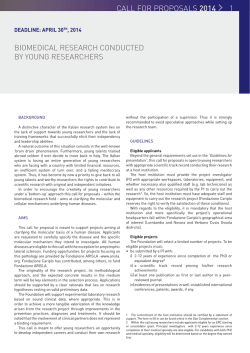
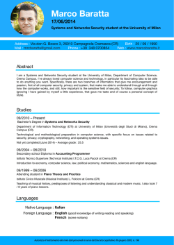
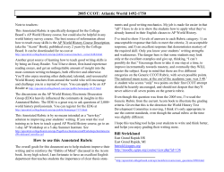
1 Introduction to VME bus Elettronicaa e acquisizione dati: VME Dottorato XXIX ciclo 20014 Industrial bus introduced in 1981 and became standard IEEE 1014-1987 Extensions: VME64 (1995), (1995) VME64x (1998) (1998), VME320 (1999) VITA - VMEbus VMEb International I t ti l Trade T d Association A i ti (www.vita.com): no-profit orgnization between HW SW producers and users of real-time real time HW-SW embedded computing, defines the VME standards Material taken from M.Joos lecture 2 Why VMEbus? Elettronicaa e acquisizione dati: VME Dottorato XXIX ciclo 20014 Complex p DAQ systems y usuallyy require q custom built electronics modules which have to be: ◦ ◦ ◦ ◦ Housed Powered Configured Read out VMEbus has traditionallyy been the technology gy of choice in manyy HEP experiments and accelerator control systems because it offers features such as: ◦ A well proven open standard that includes mechanical, electrical and protocol i sections ◦ Suitable card sizes ◦ A data transfer protocol that is relatively easy to implement ◦ An “ecosystem” of third party products (crates, processors, I/O modules, etc.) which are supported by the manufacturers for long durations Currently there are more than 1000 VMEbus systems at CERN (accelerator & experiments) VMEbus mechanics 3 VMEbus cards exist in 3 standard heights: g 3U, 6U and 9U (1U = 1.75 inch) and 2 depths: 160 mm (3U, (3U 6U) and 340 mm (9U) All cards are 0.8 inch (20.3 mm) wide 3U Dottorrato XXIX ciclo 2014 Elettronicaa e acquisizione dati: VME 9U 6U 160 mm 160 mm 340 mm 4 VMEbus mechanics Backplane p P1 3U module P2 J2 6U module 6U transition module P0 J0 ◦ various card sizes ◦ rear transition modules p ◦ backplane Backplane P1 J1 P0 J0 P2 J2 9U module P3 J3 9U ttransition module Elettronicaa e acquisizione dati: VME Dottorato XXIX ciclo 20014 P1 J1 Sectional view: 5 VMEbus mechanics Example: 6U VME64x module Elettronicaa e acquisizione dati: VME Dottorato XXIX ciclo 20014 Alignment pin Incompatible with certain old crates 5 row P1 connector 160 pins used for VMEbus 40 kg Insertion force (415 pins * 1 N) P0 connector Used for PMC I/O Incompatible with certain crates (Jaux, VME64xP) Injector / extractor handles Push button Discharge strip 5 row P2 connector 32 pins used for VMEbus Other pins user defined (e.g. for transition modules) 6 VMEbus crates Elettronicaa e acquisizione dati: VME Dottorato XXIX ciclo 20014 21 slot 9U crate (with 6U section) for 19” racks 21 slot 6U crate for 19” racks There are different types of power supplies (5V, +/ 12V, 12V 33.3V, 3V 48V) mounted locally or remotely +/The fan-tray unit allows to monitor parameters like voltages, currents, fan speeds, temperatures ((Some)) crates can be remotelyy controlled e.g. g byy a field bus (CAN) 7 VMEbus basics Classes of modules (logical) Elettronicaa e acquisizione dati: VME Dottorato XXIX ciclo 20014 ◦ Master A module that can initiate data transfers ◦ Slave A module that responds to a master ◦ Interrupter A module that can send an interrupt (usually a slave) ◦ Interrupt handler d l that h can receive ((and d hhandle) dl ) interrupts (usually ( ll a SSingle l A module Board Computer) ◦ Arbiter A piece of electronics (usually included in the SBC) that arbitrates bus access and monitors the status of the bus. It should always be installed in slot 1 of the VMEbus crate if interrupts are used 8 VMEbus basics Elettronicaa e acquisizione dati: VME Dottorato XXIX ciclo 20014 Electrical properties p p ◦ ◦ ◦ ◦ ◦ All lines use TTL levels Low = 0 ... 0.6 V High = 2.4 2 4 ... 5 V Address, address modifier and data lines are active high Protocol lines (e.g. AM, LWORD, DS0/1) are active low Protocol ◦ Asynchronous with 4-edge handshaking ◦ The duration of a VMEbus cycle depends on the speed of the master and the slave Byte ordering ◦ VMEbus is big endian. endian It stores the most significant byte of a 32-bit word at the lowest byte address (0x0) ◦ PCI and Intel CPUs are little endian. They store the most significant byte of a 32 32-bit bit word at the highest byte address (0x3) ◦ Most (but not all) VMEbus masters (e.g.VP110) have automatic byte swapping logic 9 VMEbus basics Main types yp of data transfers ◦ Single cycles Dottorato XXIX ciclo 20014 Transfer 8, 16 or 32 bits of data (typically) under the control of the CPU on the master Mnemonic: D8, D16 and D32 Typical T i l duration: d ti 1 µs + S/W overhead h d ◦ Block transfers (DMA = Direct Memory Access) Transfer any amount of data (usually 32 or 64 bit at a time) under the control of a DMA controller (CPU independent) Mnemonic: D32BLT and D64MBLT Data is transferred in bursts of up to 256 (D32) or 2048 (D64) bytes Typical duration: 150 ns per data word Elettronicaa e acquisizione dati: VME ◦ Interrupts Used typically by slaves to signal a condition (e.g. data available, internal error, etc.) Can (in principle) have 7 priorities The interrupter provides an 8-bit vector on request of the interrupt handler to identify it lf itself ROAK (Release on Acknowledge) or RORA (Release On Register Access) VMEbus addresses ◦ Either 16 16, 24 or 32 valid bits. bits Mnemonic: A16 A16, A24 or A32 ◦ A40 and A64 defined but very rarely used Signals Elettronicaa e acquisizione dati: VME Dottorato XXIX ciclo 20014 10 Name Description BBSY* Bus Busy. B B Once O a master t has h been b granted t d the th bbus it ddrives i BBSY* BBSY*. A As llong as BBSY* is i asserted no other master can get the bus A[31..1] Address lines (can carry data in D64 multiplexed transfers). A00 does not exist D[31 0] D[31..0] D t li Data lines AM[5..0] Address modifier. Defines the number of valid address bits and the cycle type DS0* and DS1* Data strobes. Tell the slave when the master is ready. Also encode the number of bytes to be transferred LWORD* Contributes to the definition of the transfer size and carries data in multiplexed block transfers AS* Address Strobe. Tells the slaves when the address on the bus is valid WRITE* D fi h di i off the h data d transfer f Defines the direction DTACK* Data acknowledge. Used by a slave to tell the master that it has read / written the data BERR* Bus error. Used by slaves or arbiters to signal errors IRQ1* .. IRQ7* Interrupt request lines. Asserted by the interrupter IACK* Interrupt acknowledge. Used by the interrupt handler to retrieve an interrupt vector from the interrupter * means ACTIVE LOW 11 Addressing Elettronicaa e acquisizione dati: VME Dottorato XXIX ciclo 20014 The VMEbus backplane has 31 address lines: A01..A31 There is no A00 address line on the backplane. This information is encoded in the DS0/1 protocol lines A slave is selected by two criteria: ◦ Address (usually 16, 24 or 32 valid bits) ◦ Address modifier (6 bits). bits) It defines: The number of valid address bits The access mode (user/supervisor, program/data, CR/CSR) The transfer type (single cycle or block transfer) Typically slaves respond to only one address width (A16, A24 or A32; read the manual of the slave) but may allow b h single both i l cycles l and d bl blockk transfers f The base address of a slave can be set: ◦ Mechanically: on-board Jumpers, Jumpers DIP switches ◦ By S/W:VME64x geographical addressing, CR/CSR 12 Data transfer: single write The number of bytes to AS* S be transferred (1, 2 or 4) 6 1 is encoded in the DS0, undefined defined undefined Addr/AM DS1 and LWORD pprotocol lines undefined undefined defined Data Remember that some 2 slaves support only certain DS* data widths ((e.g. g D8 and 5 3 4 D16 but not D32) DTACK* The VMEbus address should be aligned to the BERR* data size 1: Master drives address and AM code. Then it asserts AS 2: 2M Master puts d data on the h bus. b Then Th it i asserts DS 3: Slave latches data and drives DTACK 4: Master removes DS 5: Slave removes DTACK 6: Master releases Address, AM and data lines. Then it releases AS Elettronicaa e acquisizione dati: VME Dottorato XXIX ciclo 20014 Block Transfers 13 AS Elettronicaa e acquisizione dati: VME Dottorato XXIX ciclo 20014 Address/AM Data undefined d fi d undefined undefined defined defined defined defined defined undefined DS DTACK Th Bl f protocoll is i bbased d on the h single i l cycle l protocoll The Blockk transfer The address lines on the backplane do not change state during the transfer. Both master and slave use internal counters to keep track of the address dd As the address lines are not used they can carry data: 64-bit multiplexed DMA In this case the slave uses DTACK for two purposes: ◦ Directly after the assertion of AS to acknowledge the address ◦ After each assertion of DS to acknowledge the data 14 Performances Being a handshaked, handshaked asynchronous protocol there is no fixed transfer rate. The timing parameters (see pp limit. VMEbus standard)) however set an upper Single cycles: Typical performance = 1 µs per transfer Elettronicaa e acquisizione dati: VME Dottorato XXIX ciclo 20014 ◦ D8 = 1 MB/s ◦ D16 = 2 MB/s ◦ D32 = 4 MB/s Block transfers ◦ D32 = 20..25 MB/s (theoretical: 40 MB/s) ◦ D64 = 40..50 MB/s (theoretical: 80 MB/s) Can we go faster??? Extensions 2eVME & 2eSST Elettronicaa e acquisizione dati: VME Dottorato XXIX ciclo 20014 15 2eVME ◦ Transfer on both edges (DDR) ◦ Wait the acknowledge, still asynchronous ◦ Double the speed: up to 160 MB/s 2 SST 2eSST ◦ No acknowledge, synchronous transfer ◦ The sender provides the clock (DS1 for write write, DTACK for read) ◦ 3 speed defined:160, 267 and 320 MB/s (50, 30, 25 ns strobe width)
© Copyright 2026 Paperzz