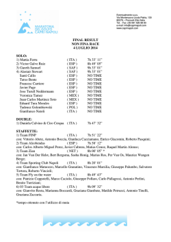
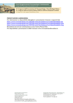
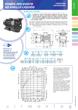
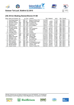
BSF 20x02-xx - 230 V BSF 40x12-xx - 24 V Pairing ENG rmBUS sysBUS Fuse Error DEU Power Pump Boiler Cool H% Master NO 1 2 3 4 FRA NDL ITA Pairing rmBUS sysBUS Fuse Error ESP Power Pump Boiler Cool H% Master NO 1 MAC 125592.1404 2 3 4 Inhalt DEU ENG FRA NDL ITA ESP 2 1 Sicherheit ......................................................................................................................3 1.1 Verwendete Signalwörter und Warnhinweise ....................................................3 1.2 Bestimmungsgemäße Verwendung.....................................................................3 1.3 Allgemeine Sicherheitshinweise ..........................................................................3 1.4 Personelle Voraussetzungen ................................................................................4 1.5 Einschränkungen für die Bedienung ...................................................................4 1.6 Konformität ..........................................................................................................4 2 Ausführungen ..............................................................................................................5 2.1 Lieferumfang ........................................................................................................5 2.2 Anzeigen und Bedienelemente ...........................................................................5 2.3 Anschlüsse .............................................................................................................6 2.4 Technische Daten ..................................................................................................7 3 Installation ....................................................................................................................8 3.1 Montage ................................................................................................................8 3.2 Elektrischer Anschluss ...........................................................................................9 3.2.1 Externes Change Over-Signal ......................................................................9 3.2.2 Anschluss Pumpe/Kessel ...............................................................................9 3.2.3 Anschluss Pumpe/Kessel .............................................................................10 3.2.5 Pilot-Funktion für Change Over Heizen/Kühlen ......................................10 3.2.4 Optionaler Feuchtefühler ..........................................................................10 3.2.6 Externe Schaltuhr anschließen ..................................................................10 3.2.7 Verwendung eines Sicherheitstemperaturbegrenzers.............................11 3.2.8 Anschluss Ethernet-Varianten ...................................................................11 4 Inbetriebnahme ..........................................................................................................12 4.1 Erstinbetriebnahme ............................................................................................12 4.2 Raumbediengerät einer Heizzone zuordnen (Pairing) ....................................12 4.3 Funktest durchführen .........................................................................................12 4.4 Basisstationen koppeln (Pairing) .......................................................................13 5[UVGOMQPƂIWTCVKQP ..........................................................................................13 5[UVGOMQPƂIWTCVKQPOKV/KETQ5&-CTVG ..................................................13 -QPƂIWTCVKQPOKV4CWODGFKGPIGTÀV(WPM&KURNC[ .................................14 4.6 Werkseinstellungen wiederherstellen ...............................................................16 5 Schutzfunktionen und Notbetrieb ............................................................................17 5.1 Schutzfunktionen ...............................................................................................17 5.1.1 Pumpenschutzfunktion..............................................................................17 5.1.2 Ventilschutzfunktion..................................................................................17 5.1.3 Frostschutzfunktion ...................................................................................17 5.1.4 Taupunktüberwachung .............................................................................17 5.1.5 Sicherheitstemperaturbegrenzer ..............................................................17 5.2 Notbetrieb .....................................................................................................17 6 Problembehebung und Reinigung ............................................................................18 6.1 Fehleranzeigen und -behebung ........................................................................18 6.2 Sicherung wechseln ............................................................................................19 6.3 Reinigung ............................................................................................................19 7 Außerbetriebnahme...................................................................................................20 7.1 Außerbetriebnahme ...........................................................................................20 7.2 Entsorgung ..........................................................................................................20 1 Sicherheit 1.1 Verwendete Signalwörter und Warnhinweise Folgende Symbole zeigen Ihnen, dass ¾ Sie etwas tun müssen. 9 eine Voraussetzung erfüllt sein muss. Warnung Lebensgefahr durch elektrische Spannung. Vor elektrischer Spannung wird durch nebenstehendes Symbol gewarnt. Warnhinweise sind durch horizontale Linien abgesetzt. 1.2 Bestimmungsgemäße Verwendung Die Basisstationen Funk 24 V und 230 V des Typs BSF x0xx2-xx dienen 9 dem Aufbau einer Einzelraumregelung (Nachregelung) mit bis zu 12 Zonen (abhängig vom verwendeten Typ) für Heiz- und Kühlsysteme, 9 dem Anschluss von bis zu 18 Stellantrieben und 12 Raumbediengeräten (abhängig vom verwendeten Typ), einer Pumpe, einem CO-Signalgeber, DEU einem Feuchtefühler mit potentialfreiem Kontakt sowie einer externen Schaltuhr. ENG 9 der ortsfesten Installationen. FRA Jegliche andere Verwendung gilt als nicht bestimmungsgemäß, für die der Hersteller nicht haftet. NDL ITA Änderungen und Umbauten sind ausdrücklich untersagt und führen zu Gefahren, für die der Hersteller nicht haftet. ESP 1.3 Allgemeine Sicherheitshinweise Warnung Lebensgefahr durch elektrische Spannung Basisstation steht unter Spannung. ¾ Vor dem Öffnen stets vom Netz trennen und gegen versehentliches Wiedereinschalten sichern. ¾ Am Pumpen- und Kesselkontakt anliegende Fremdspannungen freischalten und gegen versehentliches Wiedereinschalten sichern. Notfall ¾ Im Notfall gesamte Einzelraumregelung spannungsfrei schalten. Bewahren Sie die Anleitung auf und geben Sie sie an nachfolgende Nutzer weiter. 3 1.4 Personelle Voraussetzungen Autorisierte Fachkräfte Die Elektroinstallationen sind nach den aktuellen VDE-Bestimmungen sowie den Vorschriften Ihres örtlichen EVU auszuführen. Diese Anleitung setzt Fachkenntnisse voraus, die einem staatlich anerkannten Ausbildungsabschluss in einem der folgenden Berufe entsprechen: 3 Elektroanlagenmonteur/in oder Elektroniker/in entsprechend den in der Bundesrepublik Deutschland amtlich bekanntgemachten Berufsbezeichnungen sowie den vergleichbaren Berufsabschlüssen im europäischen Gemeinschaftsrecht. 1.5 Einschränkungen für die Bedienung Dieses Gerät ist nicht dafür bestimmt, durch Personen (einschließlich Kinder) mit eingeschränkten physischen, sensorischen oder geistigen Fähigkeiten oder mangels Erfahrung und/oder mangels Wissen benutzt zu werden, es sei denn, sie werden durch eine für ihre Sicherheit zuständige Person beaufsichtigt oder DEU erhielten von ihr Anweisungen, wie das Gerät zu benutzen ist. ENG Kinder sollten beaufsichtigt werden, um sicherzustellen, dass sie nicht mit dem FRA Gerät spielen. NDL 1.6 Konformität ITA ESP Dieses Produkt ist mit dem CE-Zeichen gekennzeichnet und entspricht damit den Anforderungen aus den Richtlinien: 9 2004/108/EG mit Änderungen „Richtlinie des Rates zur Angleichung der Rechtvorschriften der Mitgliedsstaaten über die elektromagnetische Verträglichkeit“ 9 2006/95/EG mit Änderungen „Richtlinie des Rates zur Angleichung der Rechtsvorschriften der Mitgliedstaaten betreffend elektrischer Betriebsmittel innerhalb bestimmter Spannungsgrenzen“ 9 Gesetz über Funkanlagen und Telekommunikationsendeinrichtungen (FTEG) und Richtlinie 1999/5/EG (R&TTE)“ Für die Gesamtinstallation können weitergehende Schutzanforderungen bestehen, für deren Einhaltung der Installateur verantwortlich ist. 4 2 Ausführungen 2.1 Lieferumfang Fuse 1 x* Error syBUS (nur BSF 40x12-xx) Pairing rmBUS 1x 1x Power Pump Boiler Cool H% Master 1 NO 2 3 4 1 x* * optional 2.2 Anzeigen und Bedienelemente 3 Fuse Error 4 5 6 7 8 9 Power Pump Boiler Cool H% Master NO rmBUS 2 syBUS 1 Pairing 10 1 2 3 4 DEU ENG 12 11 FRA 1 Name Fuse LED rot Funktion Leuchtet bei Defekt der Sicherung NDL 2 syBUS gelb 3 4 Error Power rot grün Zeigt Aktivität des syBUS, blinkt bei Schreibzugriff auf MicroSD-Card Leuchtet/Blinkt bei Systemfehlern Leuchtet, wenn Basisstation betriebsbereit ESP 5 6 Pump Boiler grün grün 7 Cool H% blau 8 Master gelb 9 NO gelb 10 Heizzonen 1 - x grün 11 rmBUS Taster 12 syBUS Taster - ITA Leuchtet bei aktiver Pumpenansteuerung Leuchtet bei aktiver Kesselansteuerung bei Verwendung des Boiler-Relais zur Kesselsteuerung. Leuchtet bei aktiviertem Kühlbetrieb. Blinkt, wenn Betauung festgestellt wird. .GWEJVGV)GTÀVKUV/CUVGT'KPJGKVMQPƂIWTKGTV $NKPMGP)GTÀVKUV5NCXG'KPJGKVMQPƂIWTKGTV Leuchtet, wenn Anlage für NO-Antriebe (stromlos-auf) parametriert ist. Zeigt jeweilige Aktivität der Heiz-/Kühlzonen Bedientaster für rmBUS-Funktionalität Bedientaster für syBUS-Funktionalität 5 2.3 Anschlüsse 230 V T2A T4AH 24 V L1 L2 L1‘ L2‘ TB 1 2 3 p pump boiler 1 1 1 N L N 4 2 2 ECO 1 2 CO 1 H% 2 1 2 HZ 1 1 2 1 HZ 2 2 1 2 1 2 HZ 3 HZ 4 1 1 2 2 L TB 5 6 7 8 9 10 11 12 13 14 15 16 1 DEU Anschluss Netztrafo 2 Ausgang 24 V 5 Netzanschluss N/L ITA 6 Ausgang 230 V ESP 8 9 Funktion Nur 24-V-Version: Anschluss für Systemtrafo Nur 24-V-Version: Ausgang für die Versorgung z.B. einer Sicherheitstemperaturbegrenzers (bauseitige Bereitstellung) 3/7 Temperaturbegren- Anschluss für bauseitig bereitgestellten Temperaturbegrenzer zer \WO5EJWV\GORƂPFNKEJGT1DGTƃÀEJGP(optional) 4 Schutzleiter 1 u. 2 Nur 230-V-Version: Anschlüsse für den Schutzleiter ENG FRA NDL 10 11 12 13 14 15 16 6 Nur 230-V-Version: Anschluss für die Netzversorgung Nur 230-V-Version: Optionale Belegung zur direkten Energieversorgung der Pumpe Pumpe Anschluss zur Ansteuerung der Pumpe Kessel Anschluss zur Ansteuerung des Kessels bzw. Ausgang für CO Pilot-Funktion ECO Potentialfreier Eingang für Anschluss externer Schaltuhr Change Over Potentialfreier Eingang (gemäß SELV) für externes Change Over-Signal Taupunktsensor Potentialfreier Eingang (gemäß SELV) für Taupunktsensor Stellantriebe 6 bis 18 Anschlüsse für thermische Stellantriebe RJ45-Anschluss Ethernet-Schnittstelle zur Integration der Basisstation ins (optional) Heimnetzwerk RJ12-Anschluss Anschluss für aktive Antenne MicroSD-Kartenslot Ermöglicht das Einspielen von Firmware-Updates und individuellen Systemeinstellungen. BSF BSF BSF BSF BSF BSF BSF BSF BSF BSF BSF BSF 20102-04 20202-04 20102-08 20202-08 20102-12 20202-12 40112-04 40212-04 40112-08 40212-08 40112-12 40212-12 Ethernet x x x x x x Anzahl Heizzonen 4 8 12 4 8 12 Anzahl Antriebe 2x2 + 2x1 4x2 + 4x1 6x2 + 6x1 2x2 + 2x1 4x2 + 4x1 6x2 + 6x1 Max. Nennlast 24 W aller Antriebe Schaltleist. je HZ max. 1 A Betriebsspannung 230 V / ±15% / 50 Hz 24 V / ±20% / 50 Hz Netzanschluss Klemmen NYM-Anschluss 3 x 1,5 mm² Systemtrafo mit Netzstecker Leistungsaufn. 50 W 50 W (durch Systemtrafo begrenzt) (ohne Pumpe) 0,3 W / 1,1 W / 0,3 W / 1,1 W / 0,3 W / 1,1 W / Leistungsaufn. im 1,5 W 2,4 W 1,5 W 2,4 W 1,5 W 2,4 W Leerlauf/mit Trafo 0,6 W 1,4 W 0,6 W 1,4 W 0,6 W 1,4 W Schutzklasse II Schutzgrad/ÜberIP20 / III spannungskateg. Sicherung 5 x 20 mm, T4AH 5 x 20 mm, T2A Umgebungstemp. 0 °C - 60 °C Lagertemperatur -25 °C bis +70 °C Luftfeuchtigkeit 5 - 80 % nicht kondensierend Abmessungen 225 x 52 x 75 mm 290 x 52 x 75 mm 355x 52 x 75 mm 305 x 52 x 75 mm 370 x 52 x 75 mm 435 x 52 x 75 mm Material PC+ABS Regelgenauigkeit ±1 K vom Sollwert: Regelschwingen ±0,2 K Modulation FSK Trägerfrequenz 868 MHz, bidirektional Reichweite 25 m in Gebäuden / 250 m im Freifeld Sendeleistung max. 10 mW 2.4 Technische Daten 7 DEU ENG FRA NDL ITA ESP 3 Installation 3.1 Montage Warnung Lebensgefahr durch elektrische Spannung Alle Installationsarbeiten sind in spannungsfreiem Zustand durchzuführen. DEU 1 2a 3 4 230 V 2b 24 V 5a 230 V ENG FRA NDL elektr. Anschluss, siehe Kap. 3.2 ITA ESP 5b 24 V elektr. Anschluss, siehe Kap. 3.2 8 3.2 Elektrischer Anschluss Warnung Lebensgefahr durch elektrische Spannung Alle Installationsarbeiten sind in spannungsfreiem Zustand durchzuführen. Die Verschaltung einer Einzelraumregelung hängt von individuellen Faktoren ab und muss sorgsam vom Installateur geplant und realisiert werden. Für die Steck-/Klemmanschlüsse sind nachfolgende Querschnitte verwendbar: 9 massive Leitung: 0,5 – 1,5 mm² 9 ƃGZKDNG.GKVWPIsOO 9 Leitungsenden 8 - 9 mm abisoliert 9 Leitungen der Antriebe können mit den ab Werk montierten Aderendhülsen verwendet werden. 24 V T T 230 V N L N pump boiler 1 1 2 ECO 2 1 2 CO 1 H% 2 1 2 L1 L2 L TB L1‘ L2‘ pump boiler 1 1 2 ECO 2 1 CO 2 1 H% 2 1 2 DEU TB ENG L L1 L2 3.2.1 Externes Change Over-Signal N L N pump boiler 1 1 2 2 ECO 1 2 CO 1 1 2 1 NDL 3.2.2 Anschluss Pumpe/Kessel 230 V 24 V H H% 2 FRA 2 L TB ITA 230 V T4AH N N L N pump boiler 1 1 2 2 ECO 1 2 CO 1 ESP H% 2 1 2 L TB N L Wärmeerzeuger Kühlen Heizen N L Bei Nutzung eines externen Change Over Signals schaltet die Gesamtanlage entsprechend dieses Signals zwischen Heizen und Kühlen um. Der Anschluss Boiler (Kessel) ermöglicht die Steuerung eines Wärmeerzeugers. Zusätzlich kann eine Pumpe direkt versorgt und gesteuert werden. 9 3.2.3 Anschluss Pumpe/Kessel L1‘ L2‘ pump boiler 1 1 2 ECO 2 1 2 CO 1 230 V T4AH 24 V T2A L1 L2 3.2.4 Optionaler Feuchtefühler H% 2 1 2 TB N L N pump boiler 1 1 2 ECO 2 1 2 CO 1 H% 2 1 2 L TB L N H N Feuchtefühler L Wärmeerzeuger Der Anschluss Boiler (Kessel) ermöglicht die Steuerung eines Wärmeerzeugers. Zusätzlich kann eine Pumpe gesteuert werden. DEU 3.2.5 Pilot-Funktion für Change Over Heizen/Kühlen 230 V T4AH FRA NDL ITA 3.2.6 Externe Schaltuhr anschließen N L N pump boiler 1 1 2 2 ECO 1 2 CO 1 H% 2 1 2 L TB N L N N N L L L N 230 V T4AH ENG ESP Bauseitig bereitzustellende Feuchtefühler dienen dem Schutz vor Betauung im Modus Kühlen. pump boiler 1 1 2 2 ECO 1 2 CO 1 H% 2 1 2 L TB Heizen Kühlen Steht kein externes Change OverSignal zur Verfügung, kann die interne Pilot-Funktion der Basisstation zur Umschaltung der Gesamtanlage zwischen den Betriebsmodi Heizen und Kühlen verwendet werden. Hierbei kommt ein von der Basisstation zur Umschaltung genutzes Relais zum Einsatz. 10 Die Basisstation verfügt über einen ECO-Eingang für den Anschluss einer externen Schaltuhr, wenn die interne Uhr des Raumbediengeräts Funk Display nicht genutzt werden soll. Bei Aktivierung des Eingangs durch die Schaltuhr werden die Heizzonen in den Nachtbetrieb geschaltet. 3.2.7 Verwendung eines Sicherheitstemperaturbegrenzers N L N pump boiler 1 1 2 2 ECO 1 2 CO 1 24 V T2A T4AH 230 V H% 2 1 2 L TB L1 L2 L1‘ L2‘ pump boiler 1 1 2 ECO 2 1 2 TB L N L 1 1 N Anschluss eines bauseitig bereitgestellten Sicherheitstemperaturbegrenzers (1). Dieser schaltet die Pumpe aus und schaltet den Eingang TB, wenn zu hohe Vorlauftemperaturen der Fußbodenheizung erkannt werden. Wird der TB-Eingang geschaltet fährt die Basisstation alle Antriebe automatisch zu. DEU ENG FRA NDL 3.2.8 Anschluss Ethernet-Varianten Die Basisstationen BSF xx2xx-xx verfügen über eine RJ45-Schnittstelle und einen KPVGITKGTVGP9GD5GTXGT\WT5VGWGTWPIWPF-QPƂIWTCVKQPFGU5[UVGOURGT2% Laptop und über das Internet. ¾ Basisstation per Netzwerkkabel ins Heimnetzwerk integrieren oder direkt mit PC/Laptop verbinden. Einrichtung im Heimnetzwerk: ¾ Menü des Routers (siehe Handbuch des jeweiligen Geräts) über die Adresszeile im Web-Browser (Internet Explorer, Firefox, …) aufrufen. ¾ ¸DGTUKEJVCNNGTKO0GV\YGTMDGƂPFNKEJGP)GTÀVGCP\GKIGPNCUUGP ¾ Einen Abgleich der MAC-Adresse (siehe Typenschild) durchführen, um die der Basisstation zugeordnete IP-Adresse herauszubekommen. ¾ IP-Adresse der Basisstation notieren und in die Adresszeile des Web-Browsers eingeben, um das Webinterface zu öffnen. Direkter Anschluss an PC/Laptop: ¾ Netzwerkeinstellungen im PC/Laptop aufrufen und dem PC manuell die IPAdresse 192.168.100.1 sowie die Subnetzmaske 255.255.0.0 zuweisen. ¾ Durch Eingabe der IP-Adresse 192.168.100.100 in die Adresszeile Ihres WebBrowsers erhalten Sie Zugriff auf das Webinterface. Weitere Informationen zur Einrichtung sowie zum weltweiten Zugriff über das Internet erhalten Sie unter www.ezr-home.de. 11 ITA ESP 4 Inbetriebnahme 4.1 Erstinbetriebnahme ¾ Netzspannung einschalten 9 Ist die Basisstation für NC-Antriebe parametriert, werden alle Heizzonen für 5 Minuten angesteuert, um die First-Open Funktion von NC-Antrieben zu entriegeln. 9 LED Power (Betriebsanzeige) leuchtet dauerhaft. 4.2 Raumbediengerät einer Heizzone zuordnen (Pairing) ¾ rmBUS-Taster der Basisstation Funk für 3 Sek. gedrückt halten, um den Pairing-Modus zu starten. 9 Die LED „Heizzone 1“ blinkt. ¾ Durch erneutes, kurzes Drücken die gewünschte Heizzone auswählen. 9 Angewählte Heizzone ist für 3 Minuten bereit, das Pairing-Signal eines Raumbediengeräts zu empfangen. ¾ Pairing-Funktion am Raumbediengerät aktivieren (siehe Handbuch Raumbediengerät). 9 Pairing-Modus wird verlassen, sobald eine erfolgreiche Zuordnung erfolgt. 9 Die LED der zuvor angewählten Heizzone leuchtet dauerhaft für 1 Minute. ¾ Für die Zuordnung weiterer Raumbediengeräte Vorgang wiederholen. DEU ENG FRA Tipp NDL ITA Ein Raumbediengerät kann mehreren Heizzonen zugeordnet werden. Die Zuordnung mehrerer Raumbediengeräte zu einer Zone ist nicht möglich. 4.3 Funktest durchführen ESP Das Testen der Funkübertragung erfolgt stets vom geplanten Montageort des Raumbediengeräts. 9 &KG$CUKUUVCVKQPFCTHUKEJPKEJVKO2CKTKPI/QFWUDGƂPFGP ¾ Starten Sie den Funktest am Raumbediengerät (siehe Anleitung RBG). 9 Die dem Raumbediengerät zugeordnete Heizzone wird für 1 Minute angesteuert und damit je nach Betriebszustand ein- oder ausgeschaltet. 9 Erfolgt keine Ansteuerung, sind die Empfangsbedingungen ungünstig. Verfahren Sie wie folgt: ¾ Verändern Sie unter Berücksichtigung der Montagebedingungen des Raumbediengerätes die Montageposition, bis Sie ein Empfangssignal erhalten oder ¾ Nutzen Sie das optionale Zubehör „Aktive Antenne“ oder „Repeater“ zur Verstärkung des Funksignals. Zur Installation siehe jeweiliges Handbuch. 12 4.4 Basisstationen koppeln (Pairing) Beim Einsatz mehrerer Basisstationen in einem Heizsystem können bis zu drei Geräte für den Austausch globaler Systemparameter per Funk miteinander gekoppelt werden. Die Kommunikation erfolgt Slave nach dem Master-/Slave-Prinzip. Anforderungen und Status-Meldungen werden per Funk zwischen den Einheiten ausgetauscht. Die Master-Einheit steuert Slave zentral die direkt verbundenen Funktionen/Komponenten: Master • CO Ein-/Ausgang (bei aktivierter Pilot-Funktion) • Kessel-Ausgang • Pumpen-Ausgang Hinweis: Die Basisstation, an der zuletzt eine Basisstation angemeldet wurde, wird automatisch als Master festgelegt. Die Kopplung der Basisstationen erfolgt folgendermaßen: ¾ syBUS-Taster der Basisstation Funk für 3 Sek. gedrückt halten, um den Pairing-Modus zu starten. 9 Die LED „syBUS“ blinkt. 9 Pairing-Modus ist für 3 Minuten bereit, das Pairing-Signal einer anderen Basisstation zu empfangen. ¾ syBUS-Taster an der zweiten Basisstation drücken, um den Pairing-Modus ebenfalls zu aktivieren. 9 Pairing-Modus wird verlassen, sobald eine erfolgreiche Zuordnung erfolgt. 9 Die LED „Master“ leuchtet dauerhaft an der Master-Einheit 9 Die LED „Master“ blinktYGPP$CUKUUVCVKQPCNU5NCXGMQPƂIWTKGTVYWTFG ¾ Für die Zuordnung einer weiteren Basisstation Vorgang wiederholen. 5[UVGOMQPƂIWTCVKQP &KG-QPƂIWTCVKQPFGT$CUKUUVCVKQPGTHQNIVYCJNYGKUGØDGT/KETQ5&-CTVGFKG 5QHVYCTGQDGTƃÀEJGFGT'VJGTPGV8CTKCPVGQFGTFKGService-Ebene des Raumbediengeräts Funk Display. 5[UVGOMQPƂIWTCVKQPOKV/KETQ5&-CTVG Über den EZR Manager SD Card unter www.ezr-home.de können indivuelle Einstellungen seitens des Kunden vorgenommen werden und per MicroSD-Karte (FAT16-Format zwingend erforderlich, max. 2GB) in die Basisstation übertragen werden. ¾ Öffnen Sie www.ezr-home.de über den Web-Browser Ihres PCs, wählen Sie EZR Manager SD Card und folgen Sie den Anweisungen online. ¾ Stecken Sie die MicroSD-Karte mit den aktualisierten Daten in Ihre Basisstation, der Boot-Vorgang startet automatisch 13 DEU ENG FRA NDL ITA ESP 5[UVGOMQPƂIWTCVKQPOKV/KETQ5&-CTVG (QTVU Achtung! Basisstation während des Boot-Vorgangs niemals vom Netz trennen/ MicroSD Karte niemals vor Ende des Boot-Vorgangs aus dem Gerät entfernen. 9 Während des Boot-Vorgang (ca. 2 min.) blinken die LEDs Power/Error abwechselnd. 9 Bei erfolgreicher Datenübertragung erlischt die LED Error, Power leuchtet dauerhaft 9 Bei fehlerhafter Übertragung erlischt die LED Power, Error leuchtet dauerhaft. Wenden Sie sich an den Kunden-Service. -QPƂIWTCVKQPOKV4CWODGFKGPIGTÀV(WPM&KURNC[ Die Service-Ebene des Raumbediengerätes Funk Display ist durch einen PINCode geschützt und darf ausschließlich von autorisierten Fachkräften genutzt werden. Achtung! (GJNGTJCHVG-QPƂIWTCVKQPGPHØJTGP\W(GJNGTPWPF#PNCIGPUEJÀFGP ¾ Drehknopf drücken. DEU ¾ Menü „Service-Ebene“ auswählen und durch Drücken aktivieren. ¾ 4-stellige PIN (Standard: 1234) durch Drehen und Drücken eingeben. ENG ¾ Parameter (PAr) durch erneutes Drücken auswählen und Nummer-Code des gewünschten Parameters (siehe folgende Tabelle) eingeben. FRA ¾ Parameter nach Bedarf ändern und durch Drücken bestätigen. NDL ITA Nr. Parameter Beschreibung Einheit 010 verwendetes Heizsystem je Heizzone einstellbar: Fußbodenheizung (FBH) Standard / FBH Niedrigenergie / Radiator / Konvektor passiv / Konvektor aktiv FBH St.=0 FBH NE=1 RAD=2 KON pas.=3 KON akt.=4 020 Heizen-/Kühlensperren 030 Bediensperre (Kindersicherung) Aufheben der Bediensperre passwortgeschützt ausführen Deaktiviert=0 Aktiviert=1 031 Passwort Bediensperre PIN festlegen, wenn Par. 30 auf aktiviert gesetzt 0000..9999 040 Externer Sensor am RBG angeschlossen Anmelden eines zus. Sensors zur Erfassung der Fußbodentemperatur (FBH), der Raumtemperatur oder des Taupunktes kein Sensor=0 Taupunktsen.=1 Temp FBH=2 Temp Raum=3 060 Korrektur Ist-Wert Erfassung Erfassung der Isttemperatur mit einem Korrekturfaktor versehen -2,0...+2,0 K in 0,1-Schritten ESP 14 Sperren der Schaltausgänge in Abhängigkeit des aktivierten Betriebsmodus (Heizen/Kühlen) normal=0 Heizen Sperre=1 Kühlen Sperre=2 -QPƂIWTCVKQPOKV4CWODGFKGPIGTÀV(WPM&KURNC[ (QTVU Nr. Parameter 110 Wirksinn Schaltausgang 115 Verwendung Absenkeingang 120 Beschreibung Umschaltung NC und NO Antrieben (nur global) Umschaltung zwischen Nutzung des ECO-Eingangs zur Absenkung oder der Urlaubsfunktion des RBG. Über Raumbediengerät kann die Urlaubsfunktion nicht mehr aktiviert werden, wenn Parameter auf 1 gesetzt wurde. Einheit Temperaturanzeige Umstellung der Anzeige zwischen Grad Celsius und Grad Fahrenheit Einheit NC=0 / NO=1 ECO=0 Urlaub=1 °C=0 °F=1 -QPƂIWTCVKQP2WORG 130 Pumpenausgang 131 Pumpenart 132 Vorlaufzeit der Pumpe Steuerung einer lokalen (im HKV) oder globalen (Heizungsanlage) Umwälzpumpe verwenden. lokal=0 global=1 Auswahl der verwendeten Pumpe: Konventionelle Pumpe / HQEJGHƂ\GP\Pumpe KP=0 HP=1 Zeit, die vom Zeitpunkt einer Anforderung eines Schaltausgangs bis zum Einschalten der Pumpe vergeht. [min] [min] 133 Nachlaufzeit der Pumpe Zeit, die vom Zeitpunkt des Ausschaltens der Schaltausgänge bis zum Ausschalten der Pumpe vergeht. 134 Wirksinn Schaltausgang Bei Verwendung des Pumpenrelais als Steuerausgang kann der Wirksinn invertiert werden 135 Mindestlaufzeit 136 Mindeststillstandszeit DEU ENG FRA NDL normal=0 invertiert=1 ITA Die Mindestlaufzeit gibt an wie lange die HP laufen muss bis sie wieder ausgeschaltet werden darf [min] ESP *QEJGHƂ\GP\RWORG&KG2WORGFCTHPWTCDIGschaltet werden wenn eine Mindeststillstandszeit gewährleistet werden kann. [min] -QPƂIWTCVKQP%JCPIG1XGT(WPMVKQPCNKVÀV-GUUGNTGNCKU 140 Funktion Relais Kessel / CO-Ausgang 141 Vorlaufzeit 142 Nachlaufzeit 143 Wirksinn Schaltausgang 160 Frostschutzfunktion 161 Frostschutztemperatur Auswahl ob der Schaltausgang zur Ansteuerung eines Pumpenrelais oder als CO-Pilot dienen soll Boiler=0 CO-Pilot=1 Vorlaufzeit Kesselrelais bei konv. Pumpe [min] Nachlaufzeit Kesselrelais bei konv. Pumpe [min] Bei Verwendung als Steuerausgang kann die RelaisFunktion invertiert werden. Ansteuerung der Schaltausgänge bei Tist<x°C Grenzwert für die Frostschutzfunktion normal=0 invertiert=1 Deaktiviert=0 Aktiviert=1 [°C] 15 -QPƂIWTCVKQPOKV4CWODGFKGPIGTÀV(WPM&KURNC[ (QTVU Nr. Parameter 170 Smart Start Beschreibung Anlernen des Temperaturverhaltens der einzelnen Heizzonen Einheit Deaktiviert=0 Aktiviert=1 Notbetrieb 180 Dauer bis Aktivierung Dauer bis Aktivierung der Notbetriebroutine [min] 181 PWM Zyklusdauer im Notbetrieb Dauer eines PWM-Zyklus im Notbetrieb [min] 182 Einschaltdauer PWM Heizen Ansteuerdauer im Heiz-Betrieb [%] 183 Ansteuerdauer im Kühl-Betrieb [%] [d] Einschaltdauer PWM Kühlen Ventilschutzfunktion 190 Dauer bis Aktivierung Startzeit nach letzter Ansteuerung 191 Ventilansteuerdauer Ventilansteuerdauer (0= Funktion deaktiviert) DEU Pumpenschutzfunktion ENG 200 Dauer bis Aktivierung 201 Ansteuerdauer 210 220 FRA NDL ITA ESP Startzeit nach letzter Ansteuerung [min] [d] Ansteuerdauer (0=Funktion deaktiviert) [min] First-Open-Funktion (FO) Ansteuerung aller Schaltausgänge bei Einschalten der Spannungsversorgung [min] Aus=0 Automatische Sommer-/ Winterzeitumstellung Bei aktivierter Umstellung erfolgt die Zeitanpassung automatisch nach MEZ-Richtlinien 230 Absenkdifferenztemperatur Bei Aktivierung der Absenkung über den externen Eingang Deaktiviert=0 Aktiviert=1 [K] 4.6 Werkseinstellungen wiederherstellen Achtung! Sämtliche Nutzer-Einstellungen gehen verloren. ¾ Falls vorhanden, MicroSD-Card der Basisstation entnehmen und die UserParameter-Datei am PC löschen. ¾ rmBUS-Taster der Basisstation Funk für 3 Sek. gedrückt halten, um den Pairing-Modus zu starten. 9 Die LED „Heizzone 1“ blinkt. ¾ rmBUS-Taster erneut drücken und für 10 Sekunden gedrückt halten. 9 Alle Heizzonen-LEDs blinken gleichzeitig, fangen nach weiteren 5 Sekunden gedrückt halten an, gleichzeitig zu leuchten und erlöschen im Anschluss. 9 Die Basisstation ist auf Werkeinstellung zurückgesetzt und verhält sich wie bei der Erstinbetriebnahme (siehe Kapitel 4). Hinweis! Zuvor zugeordnete Raumbediengeräte müssen neu angelernt werden. 16 5 Schutzfunktionen und Notbetrieb 5.1 Schutzfunktionen Die Basisstation verfügt über zahlreiche Schutzmaßnahmen zur Vermeidung von Schäden am Gesamtsystem. 5.1.1 Pumpenschutzfunktion Zur Vermeidung von Schäden durch längeren Stillstand wird die Pumpe innerhalb XQTFGƂPKGTVGT<GKVTÀWOGCPIGUVGWGTV9ÀJTGPFFKGUGU<GKVTCWOGUNGWEJVGVFKG.'& „Pumpe“. 5.1.2 Ventilschutzfunktion In Zeiträumen ohne Ventilansteuerung (beispielsweise außerhalb der Heizperiode), werden alle Heizzonen mit angemeldetem Raumbediengerät zyklisch angesteuert, um dem Festsetzen der Ventile vorzubeugen. 5.1.3 Frostschutzfunktion Jeder Schaltausgang verfügt über eine Frostschutzfunktion, unabhängig davon, ob er aktiviert oder deaktiviert ist und unabhängig vom Betriebsmodus. Sobald eine \WXQTRCTCOGVTKGTVG6GORGTCVWT |%WPVGTUEJTKVVGPKUVYGTFGPFKG8GPVKNG der zugeordneten Heizzone zu 100 % angesteuert, um Frostschäden zu verhindern. 5.1.4 Taupunktüberwachung DEU ENG FRA NDL ITA Ist die Anlage mit einem Taupunktsensor (bauseitige Bereitstellung) ausgestattet, werden bei Feststellung von Betauung die Ventile aller Heizzonen zugefahren, um Schäden durch Feuchtigkeit zu vermeiden. Die Auswertung vom Eingang des Taupunktsensors erfolgt nur im Kühl-Betrieb. 5.1.5 Sicherheitstemperaturbegrenzer Beim Einsatz eines optionalen Sicherheitstemperaturbegrenzers, werden beim Überschreiten einer kritischen Temperatur alle Ventile zugefahren, um Schäden an GORƂPFNKEJGP$QFGPDGNÀIGP\WXGTOGKFGP 5.2 Notbetrieb Kann die Basisstation nach Ablauf einer zuvor eingestellten Zeit keine Verbindung mehr zum der Heizzone zugeordneten Raumbediengerät herstellen, wird automatisch der Notbetrieb aktiviert. Im Notbetrieb werden die Schaltausgänge an FGT$CUKUWPCDJÀPIKIXQO*GK\U[UVGOOKVGKPGTOQFKƂ\KGTVGP29/<[MNWUFCWGT (Parameter 181) angesteuert, um das Auskühlen der Räume (im Betrieb Heizen) bzw. eine Betauung (im Betrieb Kühlen) zu vermeiden. 17 ESP 6 Problembehebung und Reinigung Fuse Pairing rmBUS Error syBUS 6.1 Fehleranzeigen und -behebung Power Pump Signalisierung der LEDs Fuse 0 Fuse Dauer in Sek. 2 3 Boiler Cool H% Master NO Bedeutung Pump Error DEU FRA NDL 0 Cool Heizzone ITA ESP HZ aus HZ an 0 HZ aus HZ an Heizzone HZ 0 18 Behebung ¾ Sicherung wechseln (siehe Kap. 6.2) 4 9 Normaler Regelbetrieb wird automatisch nach Unterschreiten der kritischen Temperatur aktiviert 4 Betauung festgestellt, Ventile werden zugefahren 9 Normaler Regelbetrieb wird automatisch aktiviert, wenn keine Betauung mehr festgestellt wird. Dauer in Sek. 1 2 3 4 Schlechte Funkverbindung zum Raumbediengerät ¾ Position des Raumbediengeräts verändern, bzw. Repeater oder aktive Antenne einsetzen. Dauer in Sek. 2 3 4 Niedrige Batteriekapazität am Raumbediengerät 1 Dauer in Sek. 2 3 Dauer in Sek. 1 2 3 1 Dauer in Sek. 1 2 3 4 Notbetrieb aktiv LED an LED aus 4 Sicherheitstemperaturbegrenzer aktiv, Ventile werden zugefahren Heizzone 0 3 Sicherung defekt „Cool H%“ (nur Kühlbetrieb) ENG 2 4 1 Error / Pump 0 1 ¾ Batterien am Raumbediengerät wechseln ¾ Batterien am Raumbediengerät wechseln ¾ Funktest durchführen. ¾ Raumbediengerät, falls erforderlich, neu positionieren. ¾ Defektes Raumbediengerät austauschen. 6.2 Sicherung wechseln Warnung Lebensgefahr durch elektrische Spannung Basisstation steht unter Spannung. ¾ Vor dem Öffnen Basisstation stets vom Netz trennen und gegen versehentliches Wiedereinschalten sichern. 1 2 3 DEU 4 5 6 ENG FRA NDL ITA ESP 6.3 Reinigung Zum Reinigen nur ein trockenes, lösungsmittelfreies, weiches Tuch verwenden. 19 7 Außerbetriebnahme 7.1 Außerbetriebnahme Warnung Lebensgefahr durch elektrische Spannung Basisstation steht unter Spannung. ¾ Vor dem Öffnen stets vom Netz trennen und gegen versehentliches Wiedereinschalten sichern. ¾ Am Pumpen- und Kesselkontakt anliegende Fremdspannungen freischalten und gegen versehentliches Wiedereinschalten sichern. ¾ Netzstecker ziehen und gesamte Anlage spannungsfrei schalten. ¾ Verkabelung zu allen extern verbundenen Komponenten wie Pumpe, Kessel und Antrieben lösen. ¾ Gerät demontieren und ordnungsgemäß entsorgen. 7.2 Entsorgung DEU Die Basisstationen dürfen nicht mit dem Hausmüll entsorgt werden. Der $GVTGKDGTKUVFC\WXGTRƃKEJVGVFKG)GTÀVGCPGPVURTGEJGPFGP4ØEMPCJmestellen abzugeben. Die getrennte Sammlung und ordnungsgemäße Entsorgung der Materialien trägt zur Erhaltung der natürlichen Ressourcen bei und garantiert eine Wiederverwertung, die die Gesundheit des Menschen schützt und die Umwelt schont. Informationen, wo Sie RückPCJOGUVGNNGPHØT+JTG)GTÀVGƂPFGPGTJCNVGP5KGDGK+JTGT5VCFVXGTYCNtung oder den örtlichen Müllentsorgungsbetrieben. ENG FRA NDL ITA ESP Made in Germany Dieses Handbuch ist urheberrechtlich geschützt. Alle Rechte vorbehalten. Es darf weder ganz noch teilweise ohne vorheriges Einverständnis des Herstellers kopiert, reproduziert, gekürzt oder in irgendeiner Form übertragen werden, weder mechanisch noch elektronisch. © 2014 20 BSF 20x02-xx - 230 V BSF 40x12-xx - 24 V Pairing ENG rmBUS sysBUS Fuse Error DEU Power Pump Boiler Cool H% Master NO 1 2 3 4 FRA NDL ITA Pairing rmBUS sysBUS Fuse Error ESP Power Pump Boiler Cool H% Master NO 1 125592.1404 2 3 4 Contents DEU ENG FRA NDL ITA ESP 22 1 Safety ..........................................................................................................................23 1.1 Used signal words and notes .............................................................................23 1.2 Intended use .......................................................................................................23 1.3 General safety notes ...........................................................................................23 1.4 Personnel-related preconditions........................................................................24 1.5 Limitations for the operation ............................................................................24 1.6 Conformity ..........................................................................................................24 2 Versions.......................................................................................................................25 2.1 Scope of supply ...................................................................................................25 2.2 Indications and operating elements ..................................................................25 2.3 Connections.........................................................................................................26 2.4 Technical data .....................................................................................................27 3 Installation ..................................................................................................................28 3.1 Assembly..............................................................................................................28 3.2 Electric connection..............................................................................................29 3.2.1 External change-over signal ......................................................................29 3.2.2 Connection of pump/boiler .......................................................................29 3.2.3 Connection of pump/boiler .......................................................................30 3.2.4 Optional humidity sensor ..........................................................................30 3.2.5 Pilot function for change-over heating/cooling.......................................30 3.2.6 Connection of external timer ....................................................................30 3.2.7 Use of a safety temperature limiter ..........................................................31 3.2.8 Connection of Ethernet variants ...............................................................31 4 Commissioning ...........................................................................................................32 4.1 First commissioning ............................................................................................32 4.2 Allocation of a room control unit to a heating zone (pairing) .......................32 4.3 Performing the radio test...................................................................................32 4.4 Coupling the base stations (pairing) .................................................................33 5[UVGOEQPƂIWTCVKQP..........................................................................................33 5[UVGOEQPƂIWTCVKQPYKVJ/KETQ5&ECTF .................................................33 %QPƂIWTCVKQPYKVJTQQOEQPVTQNWPKV9KTGNGUU&KURNC[ ..........................34 4.6 Resetting the factory settings ............................................................................36 5 Protection functions and emergency operation ......................................................37 5.1 Protection functions ...........................................................................................37 5.1.1 Pump protection function .........................................................................37 5.1.2 Valve protection function ..........................................................................37 5.1.3 Antifreeze protection function .................................................................37 5.1.4 Dew point monitoring ...............................................................................37 5.1.5 Safety temperature limiter ........................................................................37 5.2 Emergency operation .........................................................................................37 6 Troubleshooting and cleaning...................................................................................38 6.1 Error indication and elimination of errors ........................................................38 6.2 Fuse change.........................................................................................................39 6.3 Cleaning ..............................................................................................................39 7 Decommissioning .......................................................................................................40 7.1 Decommissioning ................................................................................................40 7.2 Disposal ...............................................................................................................40 1 Safety 1.1 Used signal words and notes The following symbols show you, that ¾ you must do something. 9 a precondition must be met. Warning Electrical voltage! Danger to life! The shown symbol warns against electrical voltage. Warning notes are highlighted with horizontal lines. 1.2 Intended use The base stations Radio 24 V and 230 V of the type BSF x0xx02-xx serve 9 for the arrangement of a single room regulation system (readjustment) with a maximum of 12 zones (depending on the type used) for heating and cooling systems, 9 the connection of a maximum of 18 actuators and 12 room control units (depending on the type used), a pump, a CO signalling unit, a humidity sensor with potential-free contact as well as an external timer, 9 VJGƂZGFKPUVCNNCVKQPU DEU ENG Every other use is considered as not intended; the manufacturer cannot be held liable for this. FRA NDL ITA /QFKƂECVKQPUCPFEQPXGTUKQPUCTGGZRTGUUKXGN[HQTDKFFGPCPFNGCFVQFCPIGTU the manufacturer cannot be held liable for. ESP 1.3 General safety notes Warning Electrical voltage! Danger to life! The base station is live. ¾ Always disconnect from the mains network and secure against unintended activation before opening it. ¾ Disconnect external voltages existing at the pump and the boiler contact and secure against unintended activation. Emergency ¾ In case of emergency, disconnect the complete single room control system. Retain this manual and provide it to future owners. 23 1.4 Personnel-related preconditions Authorised specialists The electrical installations must be performed according to the current VDE regulations as well as according to the regulations of your local electric power utility company. These instructions require special knowledge corresponding to CPQHƂEKCNN[CEMPQYNGFIGFdegree in one of the following professions: 3 Electrical Equipment Installer or Electronics Engineer CEEQTFKPIVQVJGRTQHGUUKQPFGUKIPCVKQPUQHƂEKCNN[CPPQWPEGFKPVJG(GFGTCN Republic of Germany, as well as according to comparable professions within the European Community Law. 1.5 Limitations for the operation DEU ENG This unit is not intended to be used by people (including children) with restricted physical, sensory or mental skills or who lack experience or knowledge, except if they are supervised by a person responsible for their safety or have received instructions on how to use this unit. Children must be monitored in order to ensure that they do not play with the device. FRA 1.6 Conformity NDL ITA This product is labelled with the CE Marking and thus is in compliance with the requirements from the guidelines: ESP 9 2004/108/EG with amendments “Council Directive on the approximation of the laws of the Member States relating to Electromagnetic Compatibility” 9 2006/95/EG with amendments “Council for Coordination of the Regulations of EU Member Countries regarding the electrical equipment for use within certain voltage limits” 9 “Radio and Telecommunications Terminal Equipment Act (FTEG) and Guideline 1999/5/EG (R&TTE)” Increased protection requirements may exist for the overall installation, the compliance of which is the responsibility of the installer. 24 2 Versions 2.1 Scope of supply 1 x* Error syBUS Fuse Pairing rmBUS 1x 1x (only BSF 40x12-xx) Power Pump Boiler Cool H% Master 1 NO 2 3 4 1 x* * optional 2.2 Indications and operating elements 3 Fuse 4 5 6 7 8 9 Power Pump Boiler Cool H% Master NO Error rmBUS 2 syBUS 1 Pairing 10 1 2 3 4 DEU ENG 12 11 1 Designation Fuse 2 syBUS FRA LED red Function Lights up when fuse has blown NDL ITA yellow 5JQYUU[$75CEVKXKV[ƃCUJGUFWTKPIYTKVKPI access on microSD card 3 Error red .KIJVUWRƃCUJGUKPECUGQHU[UVGOGTTQTU 4 Power green Lights up if the base station is ready for operation 5 Pump green Lights up when the pump control is active 6 Boiler green Lights up when boiler control is active if the boiler relay is used for boiler control. 7 Cool H% blue Lights up when cooling operation is active. Flashes if the dew point sensor shows condensation. 8 Master yellow .KIJVUWR7PKVKUEQPƂIWTGFCUOCUVGT (NCUJGU7PKVKUEQPƂIWTGFCUUNCXG 9 NO yellow Lights up if the installation is parametrized for NO actuators (normally open). 10 Heating zones 1 - x green Shows the respective activity of the heating/ cooling zones. 11 rmBUS pushbutton Pushbutton for the rmBUS functionality 12 syBUS pushbutton Push-button for the syBUS functionality ESP 25 2.3 Connections 230 V T2A T4AH 24 V L1 L2 L1‘ L2‘ TB 1 2 3 p pump boiler 1 1 1 N L N 4 2 2 ECO 1 2 CO 1 H% 2 1 2 HZ 1 1 2 1 HZ 2 2 1 2 1 2 HZ 3 HZ 4 1 1 2 2 L TB 5 6 7 8 9 10 11 12 13 14 15 16 1 DEU ENG FRA NDL ITA ESP 2 Connections Function Output 24 V Only 24 V version: Output for the supply of e. g. a safety temperature limiter (to be provided by the customer) Connections for temperature limiter for the protection of sensitive surfaces, to be provided by the customer (optional) Only 230 V version: Protective conductor connections Mains transformer Only 24 V version: Connection for system transformer 3/7 Temperature limiter 4 Protective conductor 1 and 2 5 Mains connection N/L 6 Output 230 V 8 9 10 11 Pump Boiler ECO Change over 12 Dew point sensor 13 Actuators 14 RJ45 connection (optional) 15 RJ12 connection 16 MicroSD card slot 26 Only 230 V version: Connection for mains supply Only 230 V version: Optional assignment for a direct energy supply of the pump Pump activation connection Boiler control connection, or output for CO pilot function Potential-free input for the connection of an external timer Potential-free input (according to SELV) for an external change-over signal Potential-free input (according to SELV) for dew point sensor 6 to 18 connections for thermal actuators Ethernet interface for the Integration of the base station into the home network Connection for active antenna #NNQYUVJGKPVTQFWEVKQPQHƂTOYCTGWRFCVGUCPFKPFKXKFWCN system settings. Carrier frequency Coverage Radiated power Ethernet Number of heating zones Number of actuators Max. nominal load of all actuators Switching power per heating zone Operating voltage Mains connection Power consumption (without pump) Power consumption in idle operation/with transformer Protection class Protection degree/ overvoltage category Fuse Environment temperature Storage temperature Humidity Dimensions Material Controlling precision of the target value: Hunting Modulation 2.4 W /- 225 x 52 x 75 mm 1.5 W /- 4x2 + 4x1 2x2 + 2x1 2.4 W /- 290 x 52 x 75 mm 5 x 20 mm, T4AH 1.5 W /- 50 W 12 0 °C – 60 °C IP20 / III II 0.3 W / 0.6 W 4x2 + 4x1 2x2 + 2x1 1.1 W / 1.4 W 868 MHz, bidirectional 25 m in buildings / 250 m in open air max. 10 mW ±0.2 K FSK ±1 K 1.1 W / 1.4 W 370 x 52 x 75 mm 5 x 20 mm, T2A 0.3 W / 0.6 W 12 435 x 52 x 75 mm 0.3 W / 0.6 W 1.1 W / 1.4 W 6x2 + 6x1 50 W (limited by the system transformer) 24 V / ±20% / 50 Hz System transformer with mains plug 8 4 -25 °C to +70 °C 5 to 80%, not condensing 355x 52 x 75 mm 305 x 52 x 75 mm PC+ABS 1.5 W /- max. 1 A 24 W 2.4 W /- 6x2 + 6x1 230 V / ±15% / 50 Hz NYM connection terminals 3 x 1.5 mm² 8 4 BSF BSF BSF BSF BSF BSF BSF BSF BSF BSF BSF BSF 20102-04 20202-04 20102-08 20202-08 20102-12 20202-12 40112-04 40212-04 40112-08 40212-08 40112-12 40212-12 x x x x x x 2.4 Technical data 27 DEU ENG FRA NDL ITA ESP 3 Installation 3.1 Assembly Warning Electrical voltage! Danger to life! All installation work must be performed under the absence of voltage. DEU 1 2a 3 4 230 V 2b 24 V 5a 230 V ENG FRA NDL electric connection, see section 3.2 ITA ESP 5b 24 V electric connection, see section 3.2 28 6 7 3.2 Electric connection Warning Electrical voltage! Danger to life! All installation work must be performed under the absence of voltage. The wiring of a single room control system depends on several factors and must be planned and carried through carefully by the installer. The following cross-sections are applicable for the plug-in/clamping connections: 9 solid wire: 0.5 – 1.5 mm² 9 ƃGZKDNGYKTGsOO 9 8 - 9 mm insulation stripped off the wire 9 The wires of the actuators can be used with factory-mounted end sleeves. 24 V T T 230 V pump boiler 1 1 2 ECO 2 1 2 CO 1 H% 2 1 2 pump boiler 1 1 2 ECO 2 1 CO 2 1 H% 2 1 2 DEU N L N L1 L2 L TB L1‘ L2‘ TB ENG L 3.2.1 External change-over signal N L N pump boiler 1 1 2 2 ECO 1 2 CO 1 1 FRA 3.2.2 Connection of pump/boiler NDL 230 V 24 V H H% 2 L1 L2 2 1 230 V T4AH N 2 L TB N L N pump boiler 1 1 2 2 ECO 1 2 CO 1 ESP H% 2 1 2 L TB N L boiler Cooling Heating N L If an external change-over signal is used, the overall installation switches accordingly between heating and cooling. ITA The boiler connection allows the control of a heat generator. Additionally, a pump can be controlled directly. 29 3.2.3 Connection of pump/boiler L1‘ L2‘ pump boiler 1 1 2 ECO 2 1 2 CO 1 230 V T4AH 24 V T2A L1 L2 3.2.4 Optional humidity sensor H% 2 1 2 TB N L N pump boiler 1 1 2 ECO 2 1 2 CO 1 H% 2 1 2 L TB L N H N Humidity Sensor L Wärme- boiler erzeuger The boiler connection allows the control of a heat generator. Additionally, a pump can be supplied and controlled directly. DEU 3.2.6 Connection of external timer 3.2.5 Pilot function for changeover heating/cooling 230 V T4AH FRA NDL ITA N L N pump boiler 1 1 2 2 ECO 1 2 CO 1 H% 2 1 2 L TB N L N N N L L L N 230 V T4AH ENG ESP Humidity sensors (to be provided by the customer) serve for dewing protection in the cooling mode. pump boiler 1 1 2 2 ECO 1 2 CO 1 H% 2 1 2 L TB Heating Cooling If no external change-over signal is available, the internal pilot function of the base station can be used for switching the overall installation between the operating modes Heating and Cooling. A relay used by the base station for switching over is used for this. 30 The base station is equipped with an ECO input for connecting an external timer, if the internal clock of the room control unit Radio Display shall not be used. When the input is activated by the timer, the heating zones are switched to night operation. 3.2.7 Use of a safety temperature limiter N L N pump boiler 1 1 2 2 ECO 1 2 CO 1 24 V T2A T4AH 230 V H% 2 1 2 L TB L1 L2 L1‘ L2‘ pump boiler 1 1 2 ECO 2 1 2 TB L N L 1 1 N DEU Connection of a customer-supplied safety temperature limiter (1). This device UYKVEJGUQHHVJGRWORCPFUGVUVJGKPRWVVQ6.KHVQQJKIJƃQYVGORGTCVWTGU HQTVJGƃQQTJGCVKPICTGFGVGEVGF+HVJG6.KPRWVKUUYKVEJGFVJGDCUGUVCVKQP shuts down all actuators automatically. ENG FRA 3.2.8 Connection of Ethernet variants NDL The base stations BSF xx2xx-xx are equipped with a RJ45 interface and an inteITCVGFYGDUGTXGTHQTVJGEQPVTQNCPFVJGEQPƂIWTCVKQPQHVJGU[UVGOXKC2% laptop and over the Internet. ¾ Integration of the base station into the network via network cable, or direct connection to PV/laptop Set-up in the home network ¾ Open the router menu (see manual of the respective device) via the address bar in the web browser (Internet Explorer, Firefox, …). ¾ Open an overview of all devices in the network. ¾ %QORCTGVQVJG/#%CFFTGUU UGGV[RGUKIPKPQTFGTVQƂPFQWVVJG+2CFdress allocated to the base station. ¾ Note the IP address of the base station and enter it into the address bar of the web browser in order to open the web interface. Direct connection to PC/laptop: ¾ Open the network settings in the PC/laptop and assign the IP address 192.168.100.1 as well as the subnet mask 255.255.0.0 manually to the PC. ¾ By entering the IP address 192.168.100.100 in the address bar of your web browser you will gain access to the web interface. ;QWECPƂPFHWTVJGTKPHQTOCVKQPQPVJGUGVWRCUYGNNQPYQTNFYKFGCEEGUUXKC the Internet under www.ezr-home.de. 31 ITA ESP 4 Commissioning 4.1 First commissioning ¾ Switch on the mains voltage. 9 If the base station is parameterized for NC actuators, all heating zones CTGCEVKXCVGFHQTCFWTCVKQPQHOKPWVGUKPQTFGTVQWPNQEMVJGƂTUVQRGP function of the NC actuators. 9 The power LED (operation display) lights up continuously. 4.2 Allocation of a room control unit to a heating zone (pairing) ¾ Press the rmBUS button of the base station Radio for three seconds in order to start the pairing mode. 9 6JG.'&p*GCVKPI\QPGqƃCUJGU ¾ Select the desired heating zone by pressing shortly again. 9 For three minutes, the selected heating zone is ready to receive the pairing signal of a room control unit. ¾ Activate the pairing function at the room control unit (see Room Control Unit Manual). 9 The pairing mode is left after establishing a successful allocation. 9 The LED of the heating zone previously selected will light up continuously for 1 minute. ¾ Repeat the process for allocating more room control units. DEU ENG FRA NDL Tip ITA One Room Control Unit can be allocated to various heating zones. The allocation of several room control units to one zone is impossible. 4.3 Performing the radio test ESP The radio transmission test must always be carried through at the planned installation location of the room control unit. 9 The base station must not be in pairing mode for this. ¾ Start the radio transmission test at the room control unit (see RBG manual). 9 The heating zone allocated to the room control unit is activated for one minute, thus it is switched off or on depending on the status of operation. 9 If there is no activation, the reception conditions are unfavourable. Proceed as follows: ¾ Taking into account the installation conditions of the room control unit, change the installation position until you have a reception signal, or ¾ Use the optional accessories “Active antenna” or “Repeater” in order VQCORNKH[VJGTCFKQUKIPCN;QWECPƂPFKPHQTOCVKQPQPVJGKPUVCNNCVKQP in the respective manual. 32 4.4 Coupling the base stations (pairing) If several base stations are used in one heating system, a maximum of three units can be coupled for the exchange of global system parameters via radio. Communication is done according to the Master/ Slave principle. Requirements and status messages are exchanged between the units via radio. The master unit centrally controls the directly connected functions/components. • CO input/output (if the pilot function is activated) • Boiler output • Pump output Note: The base station to which a base station was logged on lastly is automatically set as master. Slave Slave Master The base stations are coupled as follows: ¾ Press the syBUS button of the base station Radio for three seconds in order to start the pairing mode. 9 6JG.'&pU[$75qƃCUJGU 9 For three minutes, the pairing mode is ready to receive the pairing signal of another room control unit. ¾ Press the syBUS pushbutton at the second base station in order to activate the pairing mode there, too. 9 The pairing mode is left after establishing a successful allocation. 9 The LED “Master” lights up permanently at the master unit 9 The LED “Master” ƃCUJGUKHVJGDCUGUVCVKQPJCUDGGPEQPƂIWTGFCUUNCXG ¾ Repeat the process for allocating another base station. 5[UVGOEQPƂIWTCVKQP 6JGEQPƂIWTCVKQPQHVJGDCUGUVCVKQPKUFQPGQRVKQPCNN[XKCVJG/KETQ5&VJG software interface of the Ethernet variant or the Service level of the room control unit Wireless Display. 5[UVGOEQPƂIWTCVKQPYKVJ/KETQ5&ECTF The customer can perform individual settings via the EZR Manager SD Card under www.ezr-home.de and transfer these to the base station via the MicroSD card (FAT16 format is absolutely necessary, max. 2GB). ¾ Open www.ezr-home.de in the web browser of your PC, select EZR Manager SD Card and follow the instructions on-line. ¾ Insert the MicroSD card with the updated data into your base station; the boot process will start automatically. 33 DEU ENG FRA NDL ITA ESP 5[UVGOEQPƂIWTCVKQPYKVJ/KETQ5&ECTF EQPVKPWGF Attention! Never separate the base station from the mains during the boot process/never remove the MicroSD card from the device before the end of the boot process. 9 6JG.'&U2QYGT'TTQTƃCUJCNVGTPCVGN[FWTKPIVJGDQQVRTQEGUU CRRTQZ minutes). 9 After a successful data transmission, the LED Error goes out; the LED Power remains on continuously. 9 In case of faulty data transmission, the LED Power goes out and the LED Error remains on continuously. Contact the customer service. %QPƂIWTCVKQPYKVJTQQOEQPVTQNWPKV9KTGNGUU&KURNC[ The Service level of the base station Wireless Display is protected with a PIN code and may only be used by authorized specialists. Attention! (CWNV[EQPƂIWTCVKQPNGCFUVQGTTQTUCPFFCOCIGVQKPUVCNNCVKQPU ¾ Press the rotary control. DEU ¾ Select the menu “Service Level” and activate by pressing. ¾ Enter the 4-digit PIN (standard: 1234) by rotating and pressing. ENG ¾ Select parameters (PAr) by pressing again and enter the number code of the desired parameter (see following table). FRA ¾ %JCPIGRCTCOGVGTUCUTGSWKTGFCPFEQPƂTOD[RTGUUKPI NDL ITA No. 010 Parameters Used heating system Description Adjustable per heating zone: Floor heating (FBH) standard / FBH low energy / radiator / convector passive / convector active 020 Heating/cooling block Blocking the switching outputs depending on the activated operating mode (heating/cooling) ESP 030 Operation lock Unlocking the operating lock with password (child safety lock) protection 031 Operating lock password Determine PIN if parameter 30 is set to active 040 External sensor connected Logging on an additional sensor for the registration to the RBG QHVJGƃQQTVGORGTCVWTG ($*VJGTQQOVGORGTCture or the dew point 060 Correction of actual value Registration of the actual temperature with a corregistration rection factor 34 Unit FBH St.=0 FBH NE=1 RAD=2 KON pas.=3 KON act.=4 normal=0 Heating block=1 Cooling block=2 Deactivated=0 Activated=1 0000..9999 no sensor=0 Dew point sen.=1 Temp FBH=2 Temp room=3 -2.0...+2.0 K in 0.1 increments %QPƂIWTCVKQPYKVJTQQOEQPVTQNWPKV9KTGNGUU&KURNC[ EQPVKPWGF No. 110 Description Switchover of NC and NO actuators (only globally) Unit NC=0 / NO=1 Change-over between use of the ECO input for setback or holiday function of the room control unit. The holiday function cannot be activated any longer via the room control unit if the parameter has been set to 1. Toggle function of the display between degree Celsius and degree Fahrenheit ECO=0 Holiday=1 Use the control of a local recirculation pump (in the heating circuit distributor) or a global recirculation pump (heating installation). 131 Pump type Selection of the used pump: Conventional Pump / HKIJGHƂEKGPE[Pump 132 Pump line-up time Time elapsing from the moment of the command from a switching output until the pump is actually switched on. 133 Pump follow-up time Time elapsing from the moment of switching off the switching outputs until the pump is actually switched off. 134 Control direction switch- The control direction can be inverted if the pump ing output relay is used as control output 135 Minimum running time The minimum running time indicates how long the HP must run until it may be switched off again 136 Minimum standstill time *KIJGHƂEKGPE[RWOR6JGRWOROC[QPN[DG switched off if a minimum standstill time can be ensured. %QPƂIWTCVKQPQHEJCPIGQXGTHWPEVKQPCNKV[DQKNGTTGNC[ 140 Function of relay boiler / Selection whether the switching output shall serve CO output for controlling a pump relay, or as CO pilot 141 Line-up time Boiler relay line-up time for conventional pump 142 Follow-up time Boiler relay follow-up time for conventional pump 143 Control direction switch- The relay function can be inverted if used as a ing outputs control output. 160 Antifreeze protection Activation of control outputs for Tactual <x °C local=0 global=1 115 Parameters Control direction switching outputs Use as setback input 120 Unit of temperature display 2WOREQPƂIWTCVKQP 130 Pump output 161 Antifreeze temperature Antifreeze function limit value °C=0 °F=1 CP=0 HP=1 [min] DEU ENG FRA [min] NDL ITA normal=0 inverted=1 [min] ESP [min] Boiler=0 CO pilot=1 [min] [min] normal=0 inverted=1 Deactivated=0 Activated=1 [°C] 35 %QPƂIWTCVKQPYKVJTQQOEQPVTQNWPKV9KTGNGUU&KURNC[ EQPVKPWGF No. 170 Parameters Smart Start Description Learning-in of the temperature behaviour of the individual heating zones Emergency operation 180 Duration until activation Duration until the activation of the emergency operation routine 181 PWM cycle duration in Duration of a PWM cycle in emergency operation emergency operation 182 Cycle duration PWM Control duration in heating operation heating 183 Cycle duration PWM Control duration in cooling operation cooling Valve protection function DEU ENG FRA NDL 190 Duration until activation 191 Valve activation duration Pump protection function 200 Duration until activation 201 Activation duration 210 220 ITA ESP 230 [min] [min] [%] [%] Starting time after last activation Valve activation duration (0= function deactivated) [d] [min] Starting time after last activation Activation duration (0 = function deactivated) [d] [min] First open function (FO) Activation of all switching outputs at power-up Automatic switching between summer and winter time Setback difference temperature Unit Deactivated=0 Activated=1 If the conversion is activated, time adaptation is performed automatically according to CET guidelines In case of activation of the setback via the external input [min] Off=0 Deactivated=0 Activated=1 [K] 4.6 Resetting the factory settings Attention! All user settings will be lost. ¾ If present, remove the MicroSD Card from the base station and delete the WUGTRCTCOGVGTƂNGCVVJG2% ¾ Press the rmBUS button of the base station Radio for three seconds in order to start the pairing mode. 9 6JG.'&p*GCVKPI\QPGqƃCUJGU ¾ Press the rmBUS pushbutton again for a duration of 10 seconds. 9 #NNJGCVKPI\QPG.'&UƃCUJUKOWNVCPGQWUN[CHVGTCPQVJGTUGEQPFUQH pressing the pushbutton they light up simultaneously, and go out after that. 9 Now the base station is reset to factory settings and behaves as it did durKPIVJGƂTUVEQOOKUUKQPKPI UGGUGEVKQP Note! Previously allocated room control units must be learned-in newly. 36 5 Protection functions and emergency operation 5.1 Protection functions The base station is equipped with many protection functions for avoiding damage to the overall system. 5.1.1 Pump protection function In order to avoid damage by longer standstill times, the pump is activated within RTGFGƂPGFRGTKQFU6JG.'&pRWORqNKIJVUWRFWTKPIVJGUGRGTKQFU 5.1.2 Valve protection function During periods without valve activation (e. g. outside the heating period) all heating zones with logged-in room control unit are activated in a cyclic way in order to avoid clogging of the valves. 5.1.3 Antifreeze protection function DEU Every switching output, independent whether activated or deactivated, and independent from the operating mode, has an antifreeze function. As soon as a previQWUN[UGVVGORGTCVWTG %KUHCNNGPUJQTVQHVJGXCNXGUQHVJGCNNQECVGFJGCVing zone are activated to 100 % in order to avoid frost damage. ENG FRA NDL 5.1.4 Dew point monitoring If the installation is equipped with a dew point sensor (provided by the customer), the valves of all heating zones are closed if dewing is detected in order to avoid damages due to humidity. The dew point sensor input is only used during cooling operation. 5.1.5 Safety temperature limiter If an optional safety temperature limiter is used, all valves are closed when a critical VGORGTCVWTGKUGZEGGFGFKPQTFGTVQCXQKFFCOCIGVQUGPUKVKXGƃQQTEQXGTKPIU 5.2 Emergency operation If the base station is unable to establish a radio connection to the room control unit allocated to the heating zone after a set time has elapsed, emergency operation is activated automatically. In emergency operation, the switching outputs at the base CTGCEVKXCVGFYKVJCOQFKƂGF29/E[ENGFWTCVKQP RCTCOGVGTKPFGRGPFGPV from the heating system in order to avoid complete cooling of the rooms (in heating operation) or dewing (in cooling operation). 37 ITA ESP 6 Troubleshooting and cleaning Fuse Pairing rmBUS Error syBUS 6.1 Error indication and elimination of errors Power Pump Signalling of the LEDs Fuse 0 Fuse Duration in seconds 1 2 3 4 Boiler Cool H% Master NO Meaning Fuse defective Error / Pump Pump Error DEU ENG ITA ESP Cool Duration in seconds 1 2 3 4 Heating zone Duration in seconds 0 1 2 3 4 HZ on HZ an Heating zone Duration in seconds 0 1 2 3 4 HZ on HZ off LED on LED off 38 4 Elimination ¾ Change the fuse (see section 6.2) Dewing detected, valves are closed 9 The normal control operation is activated automatically if no condensation is sensed any more. Bad radio connection to the room control unit ¾ Change the position of the room control unit or use a repeater or an active antenna. Low battery capacity of the room control unit ¾ Change the batteries in the room control unit Emergency operation active ¾ Change the batteries in the room control unit ¾ Perform a radio test ¾ If necessary, reposition the room control unit. ¾ Replace a defective room control unit Heating zone Duration in seconds 0 1 2 3 4 HZ 3 9 The normal control operation is activated automatically after falling short of the critical temperature „Cool H%“ (only cooling 0 2 Safety temperature limiter active, valves are closed operation) FRA NDL 0 Duration in seconds 1 2 3 4 1 6.2 Fuse change Warning Electrical voltage! Danger to life! The base station is live. ¾ Always disconnect from the mains network and secure against unintended activation before opening the base station. 1 2 3 DEU 4 5 6 ENG FRA NDL ITA ESP 6.3 Cleaning Only use a dry and solvent-free, soft cloth for cleaning. 39 7 Decommissioning 7.1 Decommissioning Warning Electrical voltage! Danger to life! The base station is live. ¾ Always disconnect from the mains network and secure against unintended activation before opening it. ¾ Disconnect external voltages existing at the pump and the boiler contact and secure against unintended activation. ¾ Pull the mains plug and and disconnect the entire installation. ¾ Remove the wiring to all externally connected components as e. g. pump, boiler and actuators. ¾ Uninstall the device and dispose of properly. 7.2 Disposal DEU The base stations must not be disposed of with domestic waste. The operator has the duty to hand the devices to appropriate collection points. The separate collection and orderly disposal of all materials will help to conserve natural resources and ensure a recycling in a manner that protects human health and the environment. If you need information about collection points for your devices, please contact your local municipality or your local waste disposal services. ENG FRA NDL ITA ESP Made in Germany This manual is protected by copyright. All rights reserved. It may not be copied, reproduced, abbreviated or transmitted, neither in whole nor in parts, in any form, neither mechanically nor electronically, without the previous consent of the manufacturer. © 2014 40 BSF 20x02-xx - 230 V BSF 40x12-xx - 24 V Pairing ENG rmBUS sysBUS Fuse Error DEU Power Pump Boiler Cool H% Master NO 1 2 3 4 FRA NDL ITA Pairing rmBUS sysBUS Fuse Error ESP Power Pump Boiler Cool H% Master NO 1 125592.1404 2 3 4 41 Table des matières 1 Table des matières......................................................................................................43 1.1 Mots et symboles utilisés ....................................................................................43 1.2 Utilisation conforme ...........................................................................................43 1.3 Consignes générales de sécurité ........................................................................43 1.4 Exigences à satisfaire par le personnel ..............................................................44 1.5 Limitations d’utilisation......................................................................................44 1.6 Conformité ..........................................................................................................44 2 Modèles ......................................................................................................................45 2.1 Etendue de fourniture........................................................................................45 #HƂEJCIGUGVEQOOCPFGU ..................................................................................45 2.3 Connecteurs ........................................................................................................46 5RÅEKƂECVKQPUVGEJPKSWGU ...................................................................................47 3 Installation ..................................................................................................................48 3.1 Montage ..............................................................................................................48 3.2 Branchement électrique .....................................................................................49 3.2.1 Signal change-over externe .......................................................................49 3.2.2 Connecteur pompe/chaudière ...................................................................49 3.2.3 Connecteur pompe/chaudière ...................................................................50 3.2.4 Capteur d’humidité en option ..................................................................50 3.2.5 Fonction Pilot à la place du change-over chauffage/refroidissement ....50 3.2.6 Branchement d’un minuteur externe .......................................................50 3.2.7 Utilisation d’un limiteur de température de sécurité (TB) ......................51 3.2.8 Branchement des variantes Ethernet ........................................................51 4 Mise en service ...........................................................................................................52 4.1 Première mise en service ....................................................................................52 4.2 Associer la commande de température ambiante à une zone de chauffage (pairing – couplage)..................................................................................................52 4.3 Tester la liaison radio ..........................................................................................52 4.4 Coupler les stations de base (pairing) ...............................................................53 %QPƂIWTCVKQPU[UVÄOG .......................................................................................53 %QPƂIWTCVKQPU[UVÄOGCXGEECTVG/KETQ5& ..............................................53 %QPƂIWTCVKQPCXGENCEQOOCPFGFGVGORÅTCVWTGCODKCPVGRCTTCFKQ HTÅSWGPEGCXGECHƂEJGWT ....................................................................................54 4.6 Restaurer les réglages d’usine............................................................................56 5 Fonctions de protection et mode de secours ...........................................................57 5.1 Fonctions de protection .....................................................................................57 5.1.1 Fonction de protection de la pompe ........................................................57 5.1.2 Fonction de protection des vannes ...........................................................57 5.1.3 Fonction antigel .........................................................................................57 5.1.4 Monitorage du point de rosée ..................................................................57 5.1.5 Limiteur de température de sécurité ........................................................57 5.2 Mode de secours ...........................................................................................57 6 Dépannage et nettoyage...........................................................................................58 #HƂEJCIGUFoGTTGWTGVFÅRCPPCIG.....................................................................58 6.2 Changer le fusible ...............................................................................................59 6.3 Nettoyage............................................................................................................59 7 Mise hors service ........................................................................................................60 7.1 Mise hors service .................................................................................................60 7.2 Elimination ..........................................................................................................60 DEU ENG FRA NDL ITA ESP 42 1 Table des matières 1.1 Mots et symboles utilisés Les symboles suivants vous indiquent que ¾ vous devez faire quelque chose 9 une condition doit être satisfaite. Avertissement Danger de mort par tension électrique. Ce symbole prévient de la présence de tension électrique. Les avertissements sont placés entre deux lignes horizontales. 1.2 Utilisation conforme .GUUVCVKQPUFGDCUGUCPUƂN8GV8FGV[RG$5(ZZZZZRGTOGVVGPV 9 la mise en place d’une régulation (réajustement) pour systèmes de chauffage et de refroidissement de pièces indépendantes prévoyant jusqu’à 12 zones (suivant le type utilisé) ; 9 le raccordement au maximum de 18 actionneurs et de 12 commandes de température ambiante (suivant le type utilisé), d’une pompe, d’un générateur de signaux CO, d’un capteur d’humidité à contact sec ainsi que d’un minuteur externe ; 9 FGUKPUVCNNCVKQPUƂZGU DEU ENG FRA Toute autre utilisation est à considérer comme non conforme et dégage le fabriNDL cant de toute responsabilité. ITA +NGUVHQTOGNNGOGPVKPVGTFKVFoCRRQTVGTFGUOQFKƂECVKQPUGVVTCPUHQTOCVKQPU celles-ci étant à l’origine de dangers qui n’entraînent pas la responsabilité du fabricant. ESP 1.3 Consignes générales de sécurité Avertissement Danger de mort par tension électrique. La station de base se trouve sous tension. ¾ Avant d’ouvrir, toujours couper du réseau électrique et protéger contre un redémarrage intempestif. ¾ Déconnecter les tensions parasites au contact de la pompe et de la chaudière et protéger contre toute remise sous tension intempestive. Cas d’urgence ¾ En cas d’urgence, mettre hors tension toute la régulation indépendante des pièces. Conservez la notice et, le cas échéant, remettez-la au nouveau propriétaire.weiter. 43 1.4 Exigences à satisfaire par le personnel 2GTUQPPGNSWCNKƂÅCITÅÅ Les installations électriques doivent être réalisées en conformité avec les dispositions VDE en vigueur ainsi qu’avec les directives publiées par votre compagnie distributrice. La présente notice requiert des connaissances dont disposent les personnes ayant obtenu un titre de formation professionnelle reconnu par l’Etat tel que : 3 monteur d’installations électriques ou électronicien EQPHQTOÅOGPVCWZPQOUQHƂEKGNUFGOÅVKGTSWKGZKUVGPVGP4ÅRWDNKSWGHÅFÅTCNG d’Allemagne ou aux titres équivalents discernés dans les autres pays de l’Union européenne. 1.5 Limitations d’utilisation Cet appareil n’est pas destiné à être utilisé par des personnes (y compris les enfants) avec des capacités physiques, sensorielles et intellectuelles limitées, ou par des personnes non expérimentées et/ou n’ayant pas les connaissances DEU requises, à moins qu’elles ne soient sous la surveillance d’une personne responsable de leur sécurité ou qu’elles aient reçu de cette personne des directives ENG concernant l’utilisation de l’appareil. FRA Les enfants doivent être surveillés pour s’assurer qu’ils ne s’amusent pas avec NDL l’appareil. ITA ESP 1.6 Conformité Ce produit porte le label CE conformément aux dispositions des directives suivantes : 9 %'OQFKƂÅGRCTNC&KTGEVKXGFW%QPUGKN'WTQRÅGPRQWTNoJCTOQnisation des législations des Etats membres en matière de compatibilité électromagnétique » 9 %'OQFKƂÅGRCTNC&KTGEVKXGFW%QPUGKN'WTQRÅGPRQWTNoJCTOQPKsation des législations des Etats membres en matière de matériel électrique destiné à être employé dans certaines limites de tension » 9 NCNQKUWTNGUÅSWKRGOGPVUTCFKQGVVGTOKPCWZFGVÅNÅEQOOWPKECVKQP (FTEG) et la directive dite ‘R&TTE’ (Radio And Terminal Telecommunication Equipement) » L’installation dans son entièreté peut comporter des exigences de protection supplémentaires qu’il revient à l’installateur de respecter. 44 2 Modèles Fuse 1 x* Error syBUS 1x 1x (uniquement BSF 40x12-xx) Pairing rmBUS 2.1 Etendue de fourniture Power Pump Boiler Cool H% Master 1 NO 2 3 4 1 x* * en option #HƂEJCIGUGVEQOOCPFGU 3 Fuse Error 4 5 6 7 8 9 Power Pump Boiler Cool H% Master NO rmBUS 2 syBUS 1 Pairing 10 1 2 3 4 DEU ENG 12 11 FRA 1 Nom Fuse LED rouge Fonction s’allume en cas de défaut du fusible 2 syBUS jaune 3 4 Error Power rouge vert 5 6 Pump Boiler vert vert 7 Cool H% bleu 8 Master jaune 9 NO jaune #HƂEJGNoCEVKXKVÅFWU[$75ENKIPQVGGPECUFoÅETKVWTGUWT la carte MicroSD-Card s’allume/clignote en cas d’erreurs système s’allume quand la station de base est prête à fonctionner s’allume quand la commande de la pompe est active s’allume quand la commande de la chaudière est active et qu’un relais de chaudière est utilisé pour la commande de celle-ci. s’allume quand le mode de refroidissement est activé s’allume quand de la rosée est constatée UoCNNWOGSWCPVNoCRRCTGKNGUVEQPƂIWTÅEQOOGOCÊVTG ENKIPQVGSWCPFNoCRRCTGKNGUVEQPƂIWTÅEQOOGGUENCXG s’allume quand l’installation est paramétrée pour actionneurs NO (sans courant-ouvert). indique l’activité des différentes zones de chauffage/ refroidissement touche de commande pour la fonctionnalité rmBUS Touche de commande pour fonctionnalité syBUS 10 Zones de chauf- vert fage de 1 à x 11 Touche rmBUS 12 Touche syBUS - NDL 45 ITA ESP 2.3 Connecteurs 230 V T2A T4AH 24 V L1 L2 L1‘ L2‘ TB 1 2 3 p pump boiler 1 1 1 N L N 4 2 2 ECO 1 2 CO 1 H% 2 1 2 HZ 1 1 2 1 HZ 2 2 1 2 1 2 HZ 3 HZ 4 1 1 2 2 L TB 5 6 7 8 9 10 11 12 13 14 15 16 Connecteur DEU ENG FRA NDL ITA ESP 1 Fonction uniquement version 24 V : connecteur pour transformateur système 2 uniquement version 24 V : sortie pour l’alimentation par ex. d’un limiteur de température de sécurité (il revient au client de le fournir) 3/7 Limiteur de tempé- connecteur pour limiteur de température fourni par le client, rature destiné à protéger les surfaces délicates (en option) 4 Conducteurs de uniquement version 230 V : connecteurs pour le conducteur de protection 1 et 2 protection 5 Branchement sec- uniquement version 230 V : connecteur pour l’alimentation teur N/L secteur 6 Sortie 230 V uniquement version 230 V : utilisable en option pour approvisionner directement la pompe en énergie électrique 8 Pompe connecteur pour la commande de la pompe 9 Chaudière connecteur pour la commande de la chaudière ou sortie pour la fonction CO Pilot 10 ECO Entrée sans potentiel pour un minuteur externe 11 Change-over Entrée sans potentiel (selon SELV) pour signal change over externe 12 Capteur du point Entrée sans potentiel (selon SELV) pour capteur du point de de rosée rosée 13 Actionneurs de 6 à 18 connecteurs pour actionneurs thermiques 14 Connecteur RJ45 Interface Ethernet pour intégrer la station de base dans le (en option) réseau domestique 15 Connecteur RJ12 Raccord pour antenne active 16 Slot de carte RGTOGVNGVÅNÅEJCTIGOGPVFGUOKUGU¼LQWTFWƂTOYCTGGVNC MicroSD personnalisation des paramètres système. 46 Transformateur secteur Sortie 24 V Fréquence porteuse Portée Puissance de transmission Ethernet Nbr zones de chauffage Nbr d’actionneurs Charge nom. maxi de tous les actionneurs Capacité de coupure par HZ Tension de service Branchement secteur Puiss. absorbée (sans pompe) Puiss. absorbée en marche à vide/avec transformateur Classe de protection Indice de protection/catég. de surtension Fusible Temp. ambiante Temp. de stockage Humidité de l’air Dimensions Matériau Précision de réglage de la valeur de consigne : Oscillation de régulation Modulation 2,4 W 2,4 W 290 x 52 x 75 mm 5 x 20 mm, T4AH 1,5 W 50 W 12 IP20 / III II 0,3 W / 0,6 W 4x2 + 4x1 2x2 + 2x1 1,1 W / 1,4 W max. 10 mW 868 MHz, bidirectionnel 25 m dans les bâtiments / 250 m à l’extérieur FSK ±0,2 K ±1 K 1,1 W / 1,4 W 370 x 52 x 75 mm 5 x 20 mm, T2A 0,3 W / 0,6 W 435 x 52 x 75 mm 0,3 W / 0,6 W 50 W (limité par le transformateur système) 1,1 W / 1,4 W 6x2 + 6x1 12 VTCPUHQTOCVGWTU[UVÄOGCXGEƂEJGFoCNKOGPVCVKQP 24 V / ±20% / 50 Hz 8 4 de 0°C à 60°C de -25°C à +70°C de 5 à 80 %, non condensant 355x 52 x 75 mm 305 x 52 x 75 mm PC+ABS 1,5 W 24 W max. 1 A 2,4 W 6x2 + 6x1 bornes de connexion NYM 3 x 1,5 mm² 225 x 52 x 75 mm 1,5 W 4x2 + 4x1 2x2 + 2x1 230 V / ±15% / 50 Hz 8 4 BSF BSF BSF BSF BSF BSF BSF BSF BSF BSF BSF BSF 20102-04 20202-04 20102-08 20202-08 20102-12 20202-12 40112-04 40212-04 40112-08 40212-08 40112-12 40212-12 x x x x x x 5RÅEKƂECVKQPUVGEJPKSWGU DEU 47 ENG FRA NDL ITA ESP 3 Installation 3.1 Montage Avertissement Danger de mort par tension électrique. Tous les travaux d’installation doivent être exécutés en l’absence de tension. DEU 1 2a 3 4 230 V 2b 24 V 5a 230 V ENG FRA NDL branchement électr., voir chap. 3.2 ITA ESP 5b 24 V branchement électr., voir chap. 3.2 48 6 7 3.2 Branchement électrique Avertissement Danger de mort par tension électrique. Tous les travaux d’installation doivent être exécutés en l’absence de tension. Le câblage d’une régulation indépendante des pièces dépend de facteurs indiviFWGNUGVFQKVÆVTGRNCPKƂÅGVTÅCNKUÅCXGEUQKPRCTNoKPUVCNNCVGWT .GUUGEVKQPUUWKXCPVGURGWXGPVÆVTGWVKNKUÅGURQWTNGUEQPPGEVGWTU¼ƂEJGDQTPG 9 conducteur massif : de 0,5 à 1,5 mm² 9 EQPFWEVGWTƃGZKDNGFG¼OO 9 Extrémités de câble 8 - 9 mm isolées 9 Les conducteurs des actionneurs peuvent être utilisés avec les embouts montés en usine. 24 V T T 230 V pump boiler 1 1 2 ECO 2 1 2 CO 1 H% 2 1 2 pump boiler 1 1 2 ECO 2 1 CO 2 1 H% 2 1 2 DEU N L N L1 L2 L TB L1‘ L2‘ TB ENG L L1 L2 3.2.2 Connecteur pompe/chaudière NDL 3.2.1 Signal change-over externe N L N pump boiler 1 1 2 2 ECO 1 2 CO 1 230 V 24 V H H% 2 1 2 FRA 1 230 V T4AH N 2 L TB N L N pump boiler 1 1 2 2 ECO 1 2 CO 1 H% 2 1 2 L TB N L Génér. de chaleur Refroid. Chauffage N L En cas d’utilisation d’un signal changeover externe, l’ensemble de l’installation bascule entre chauffage et refroidissement en fonction de ce signal. Le connecteur Boiler (chaudière) permet la commande d’un générateur de chaleur. De plus, il est possible d’alimenter et de commander directement une pompe. 49 ITA ESP 3.2.3 Connecteur pompe/ chaudière 3.2.4 Capteur d’humidité en option L1 L2 L1‘ L2‘ pump boiler 1 1 2 ECO 2 1 2 CO 1 230 V T4AH T2A 24 V H% 2 1 2 TB N L N pump boiler 1 1 2 ECO 2 1 2 CO 1 H% 2 1 2 L TB L N H N Capteur d’humidité L WärmeGénér. de chaleur erzeuger Le connecteur Boiler (chaudière) permet la commande d’un générateur de chaleur. De plus, il est possible et de commander directement une pompe. DEU En mode refroidissement, les capteurs d’humidité fournis par le client protègent de la rosée. 3.2.5 Fonction Pilot à la place du change-over chauffage/refroidissement 230 V T4AH FRA NDL 3.2.6 Branchement d’un minuteur externe pump boiler 1 1 2 2 ECO 1 2 CO 1 230 V T4AH ENG H% 2 1 2 pump boiler 1 1 2 2 ECO 1 2 CO 1 H% 2 1 2 ITA N L N L TB N L N L TB ESP N N L L L N Chauffage Refroid. En l’absence d’un signal change-over externe, il est possible d’utiliser la fonction Pilot interne de la station de base pour faire basculer l’ensemble de l’installation entre les modes de fonctionnement Chauffage et Refroidissement. Pour ce faire, la station de base se sert d’un relais. 50 La station de base est équipée d’une entrée ECO pour le branchement d’un minuteur externe, s’il ne faut pas utiliUGTNGOKPWVGWTKPVGTPGFGNoCHƂEJCIG radio de la commande de température ambiante. L’activation de l’entrée par le minuteur fait basculer les zones de chauffage en mode Nuit. 3.2.7 Utilisation d’un limiteur de température de sécurité (TB) N L N pump boiler 1 1 2 2 ECO 1 2 CO 1 24 V T2A T4AH 230 V H% 2 1 2 L TB L1 L2 L1‘ L2‘ pump boiler 1 1 2 ECO 2 1 2 TB L N L 1 1 N Raccordement d’un limiteur de température de sécurité mis à disposition par le client (1). Ce limiteur arrête la pompe et active l’entrée TB dès que l’appareil détecte que les températures montantes du sol chauffant sont trop élevées. Dès activation de l’entrée TB, la station de base arrête automatiquement tous les actionneurs. 3.2.8 Branchement des variantes Ethernet DEU ENG FRA NDL Les stations de base BSF xx2xx-xx sont équipées d’une interface RJ45 et d’un serXGWTYGDKPVÅITÅRQWTEQOOCPFGTGVEQPƂIWTGTNGU[UVÄOGUWT2%QTFKPCVGWT portable et via Internet. ¾ Intégrer la station de base dans le réseau en utilisant un câble réseau ou la relier directement au PC/à l’ordinateur portable. Installation au réseau : ¾ Ouvrir le menu du routeur (voir manuel de l’appareil respectif) en saisissant son url dans la barre d’adresse du navigateur web (Internet Explorer, Firefox, ...). ¾ #HƂEJGTWPGXWGFoGPUGODNGFGVQWUNGUCRRCTGKNURTÅUGPVUFCPUNGTÅUGCW ¾ Via l’adresse MAC (voir la plaque signalétique), trouver l’adresse IP associée à la station de base. ¾ Noter l’adresse IP de la station de base puis la saisir dans la barre d’adresse du navigateur web pour accéder à l’interface web. Branchement direct au PC/à l’ordinateur portable : ¾ Ouvrir les paramétrages de réseau sur le PC/l’ordinateur portable et lui attribuer manuellement l’adresse IP 192.168.100.1 et le masque du sous réseau 255.255.0.0. ¾ En saisissant l’adresse IP 192.168.100.100 dans la barre d’adresse de votre navigateur web, vous avez accès à l’interface web. D’autres informations concernant l’installation et l’accès mondial via Internet vous sont fournies sous www.ezr-home.de. 51 ITA ESP 4 Mise en service 4.1 Première mise en service ¾ Connecter la tension de réseau 9 Si la station de base est paramétrée pour les actionneurs NC, toutes les zones de chauffage seront activées pendant 5 minutes pour déverrouiller la fonction First-Open des actionneurs NC. 9 La LED Power (voyant de fonctionnement) reste allumée en permanence. 4.2 Associer la commande de température ambiante à une zone de chauffage (pairing – couplage) ¾ #RRW[GTRGPFCPVUUWTNCVQWEJGTO$75FGNCUVCVKQPFGDCUGUCPUƂN pour démarrer le mode de pairing. 9 .C.'&<QPGFGEJCWHHCIGENKIPQVG ¾ En appuyant une nouvelle fois, pour un court instant, choisir la zone de chauffage voulue. 9 La zone de chauffage choisie est prête pendant trois minutes à recevoir le signal de pairing d’une commande de température ambiante. ¾ Activer la fonction de pairing sur la commande de température ambiante (voir le manuel de la commande de température ambiante). 9 Le mode de pairing se désactive dès que la commande est associée à une zone. 9 La LED de la zone de chauffage sélectionnée au préalable reste allumée pour 1 minute. ¾ Répéter la procédure pour associer d’autres commandes de température ambiante. DEU ENG FRA NDL ITA ESP Conseil Une commande de température ambiante peut être associée à plusieurs zones de chauffage. En revanche, l’association de plusieurs commandes de température ambiante à une zone n’est pas possible. 4.3 Tester la liaison radio La liaison radio est toujours testée depuis l’endroit où il est envisagé de placer la commande de température ambiante. 52 9 La station de base ne doit pas se trouver en mode de pairing. ¾ Démarrez le test de la liaison radio sur la commande de température ambiante (voir la notice de celle-ci). 9 La zone de chauffage associée à la commande de température ambiante sera alors activée ou désactivée pendant 1 minute en fonction du mode utilisé au moment du test. 9 En cas de non-réaction, cela veut dire que les conditions de réception sont défavorables. Si tel est le cas, procédez comme suit : ¾ En tenant compte des conditions de montage de la commande de température ambiante, changez la position de montage jusqu’à recevoir un signal, ou ¾ 7VKNKUG\NoCEEGUUQKTGGPQRVKQP#PVGPPGCEVKXGQW4ÅRÅVGWTRQWT CORNKƂGTNGUKIPCNTCFKQ2QWTNoKPUVCNNCVKQPXQKTNGOCPWGNFGNoCEEGUsoire utilisé. 4.4 Coupler les stations de base (pairing) En cas d’utilisation de plusieurs stations de base au sein d’un système de chauffage, il est possible de EQWRNGTGPVTGGWZUCPUƂNCWOCZKOWOVTQKUCRRCreils pour l’échange de paramètres système globaux. Esclave La communication se déroule suivant le principe maître/esclave. Les requêtes et les messages d’état UQPVÅEJCPIÅUUCPUƂNGPVTGNGUWPKVÅU.oWPKVÅOCÊVTG Esclave contrôle centralement les fonctions/composants directement reliés : Maître • entrée/sortie CO (avec la fonction Pilot activée) • sortie chaudière • sortie pompe Remarque : la dernière station de base à laquelle WPGUVCVKQPFGDCUGUoGUVEQPPGEVÅGGUVCWVQOCVKSWGOGPVEQPƂIWTÅGEQOOG maître. Le couplage des stations de base se déroule de la manière suivante : ¾ #RRW[GTRGPFCPVUUWTNCVQWEJGU[$75FGNCUVCVKQPFGDCUGUCPUƂNRQWT DEU démarrer le mode de pairing. ENG 9 .C.'&U[$75ENKIPQVG 9 Le mode de pairing est prêt pendant trois minutes à recevoir le signal de FRA pairing d’une autre station de base. ¾ Appuyer sur la touche syBUS de la deuxième station de base pour activer là NDL aussi le mode de pairing. ITA 9 Le mode de pairing se désactive dès que la commande est associée à une zone. ESP 9 .C.'&/CUVGTreste allumée en permanence sur l’unité maître 9 .C.'&/CUVGTclignoteSWCPFNCUVCVKQPFGDCUGGUVEQPƂIWTÅGEQOOG esclave. ¾ Répéter la procédure pour associer une autre station de base. %QPƂIWTCVKQPU[UVÄOG .CUVCVKQPFGDCUGRGWVÆVTGEQPƂIWTÅGCWEJQKZXKCWPGECTVG/KETQ5&XKC l’interface logicielle de la variante Ethernet ou via le niveau de serviceFGNoCHƂchage de la commande de température ambiante par radio fréquence. %QPƂIWTCVKQPU[UVÄOGCXGEECTVG/KETQ5& Via le Manager EZR SD Card sous www.ezr-home.de le client peut effectuer des paramétrages personnalisés et les transmettre à la station de base à l’aide de la carte MicroSD (format FAT16 obligatoire, 2 Go max.). ¾ Ouvrez la page www.ezr-home.de sur le navigateur de votre PC, sélectionnez EZR Manager SD Card et suivez les instructions en ligne. ¾ Insérez la carte MicroSD avec les données à jour dans votre station de base. La procédure de boot démarrera alors automatiquement. 53 %QPƂIWTCVKQPU[UVÄOGCXGEECTVG/KETQ5& UWKVG Attention ! Ne jamais débrancher la station de base pendant le processus de FÅOCTTCIGPGLCOCKUTGVKTGTNCECTVG/KETQ5&FGNoCRRCTGKNCXCPVNCƂPFWRTQcessus de démarrage 9 Pendant la procédure de boot (env. 2 min.), les LED Power/Error clignotent en alternance. 9 En cas de transfert de données réussi, la LED Error s’éteigne, tandis que Power reste allumé en permanence. 9 En cas d’échec de transfert de données, la LED Power s’éteigne, tandis que Error reste allumé en permanence. Adressez-vous au service clientèle. %QPƂIWTCVKQPCXGENCEQOOCPFGFGVGORÅTCVWTGCODKCPVGRCTTCFKQ HTÅSWGPEGCXGECHƂEJGWT DEU ENG FRA NDL ITA ESP Le niveau de service de la commande de température ambiante par radio HTÅSWGPEGCXGECHƂEJGWTGUVRTQVÅIÅRCTWPEQFG2+0GVFQKVÆVTGWVKNKUÅWPKSWGOGPVRCTWPRGTUQPPGNSWCNKƂÅCITÅÅ Attention ! &GUEQPƂIWTCVKQPUGTTQPÅGUUQPVNCECWUGFoGTTGWTUGVFGFQOOCIGU à l’installation. ¾ Appuyer sur le bouton. ¾ %JQKUKTNGOGPW0KXGCWFGUGTXKEGRWKUNoCEVKXGTGPCRRW[CPV ¾ Saisir le PIN à 4 chiffres (par défaut : 1234) en tournant et en appuyant. ¾ Choisir le paramètre (PAr) en appuyant une nouvelle fois, puis saisir le code numérique du paramètre voulu (voir le tableau suivant). ¾ Changer au besoin le paramètre puis valider en appuyant. N° 010 Paramètre Description Système de chauffage utilisé Réglable en fonction de la zone de chauffage : Chauffage par le plancher standard (FBH) / basse consommation d’énergie FBH / radiateur / convecteur passif / convecteur actif 020 Verrouillage chauffage/refroi- Verrouiller les sorties de commutation en fonction du mode dissement de fonctionnement (chauffage/refroidissement) 030 Verrouillage commande (sécurité enfant) 031 040 54 Unité FBH st.=0 FBH basse cons. éner.=1 RAD=2 CONV pas.=3 CONV act.=4 Normal=0 Chauffage verrouillage=1 Refroidissement verrouillage=2 Déverrouillage de la commande protégé par mot de passe Désactivé=0 Activé=1 Mot de passe verrouillage commande &ÅƂPKTNG2+0SWCPFNGRCTGUVTÅINÅUWTCEVKXÅ 0000..9999 Capteur externe relié à la commande RBG Ajouter un capteur suppl. pour mesurer la température au sol Pas de capteur=0 (FBH), la température ambiante ou le point de rosée Capt. point rosée=1 Temp FBH=2 Temp pièce=3 %QPƂIWTCVKQPCXGENCEQOOCPFGFGVGORÅTCVWTGCODKCPVGRCTTCFKQ HTÅSWGPEGCXGECHƂEJGWT UWKVG N° 060 110 Paramètre Correction mesure de la valeur réelle Description Pourvoir la mesure de la température réelle d’un facteur de correction Sens d’action sortie de com- Basculement entre actionneurs NC et NO (uniquement mutation global) 115 Utilisation entrée abaissement Basculement entre l’utilisation de l’entrée ECO pour une baisse de température ou la fonction Vacances de la commande de température ambiante. Si le paramètre est sur 1, la fonction Vacances de peut plus être activée par la commande de température ambiante. 120 7PKVÅCHƂEJCIGFGVGORÅrature $CUEWNGOGPVFGNoCHƂEJCIGGPVTGFGITÅ%GNUKWUGVFGITÅ Fahrenheit Unité -2,0...+2,0 K A pas de 0,1 NC=0 / NO=1 ECO=0 Vacances=1 °C=0 °F=1 %QPƂIWTCVKQPFGNCRQORG Local=0 Global=1 130 Sortie pompe Utiliser la commande d’une pompe de circulation locale (dans un collecteur HKV) ou globale (installation de chauffage). 131 Type pompe Choix de la pompe utilisée : pompe conventionnelle (KPRQORG¼JCWVGGHƂECEKVÅ HP) KP=0 HP=1 DEU 132 Temps de démarrage de la pompe Temps qui s’écoule entre le moment d’une demande d’une sortie de commutation jusqu’à la mise en marche de la pompe. [min] ENG 133 Temps d’arrêt de la pompe Temps qui s’écoule entre le moment de déconnexion d’une sortie de commutation jusqu’à l’arrêt de la pompe. [min] 134 Sens d’action sortie de com- L’utilisation du relais de pompe comme sortie de commande mutation permet d’inverser le sens d’action 135 Durée de marche mini 136 Durée d’arrêt mini FRA NDL Normal=0 Inversé=1 La durée de marche mini indique pendant combien de temps la pompe HP doit fonctionner avant de pouvoir être arrêtée [min] 2QORG¼JCWVGGHƂECEKVÅCTTÆVGTNCRQORGWPKSWGOGPV quand il est possible d’assurer une durée d’arrêt mini. [min] ITA ESP %QPƂIWTCVKQPFGNCHQPEVKQPPCNKVÅFGEJCPIGQXGTTGNCKUFGNCEJCWFKÄTG 140 Fonction relais chaudière / sortie CO Choisir si la sortie de commutation doit servir de commande pour un relais de pompe, ou comme CO Pilot Boiler=0 CO Pilot=1 141 Temps de démarrage Relais de chaudière temps de démarrage pour pompe conv. [min] 142 Temps d’arrêt Relais de chaudière temps d’arrêt pour pompe conv. [min] 143 Sens d’action sortie de com- L’utilisation comme sortie de commande permet d’inverser la mutation fonction de relais. 160 Fonction antigel 161 Température antigel 170 Smart Start Commande des sorties de commutation pour Tréelle<x°C Valeur seuil pour la fonction antigel Apprentissage du comportement thermique des différentes zones de chauffage Normal=0 Inversé=1 Désactivé=0 Activé=1 [°C] Désactivé=0 Activé=1 Mode de secours 180 Délai d’activation Délai d’activation de la routine du mode de secours [min] 55 %QPƂIWTCVKQPCXGENCEQOOCPFGFGVGORÅTCVWTGCODKCPVGRCTTCFKQ HTÅSWGPEGCXGECHƂEJGWT UWKVG N° 181 Paramètre Description Durée de cycle MIL en mode Durée d‘un cycle MIL en mode d‘urgence d‘urgence 182 Durée de cycle MIL chauffage Durée de commande en mode de chauffage 183 Durée de cycle MIL refroidis- Durée de commande en mode de refroidissement sement Unité [min] [%] [%] Fonction de protection des vannes 190 Délai d’activation 191 Durée de commande des vannes Temps de démarrage depuis la dernière commande Durée de commande des vannes (0= fonction désactivée) [d] [min] Fonction de protection de la pompe DEU 200 Délai d’activation 201 Durée de commande 210 Fonction First-Open (FO) 220 ENG FRA 230 Temps de démarrage depuis la dernière commande Durée de commande (0= fonction désactivée) Commande de toutes les sorties de commutation pour démarrer l’alimentation Passage automatique de En cas de passage automatique de l’heure activé, celui-ci se l’heure d’été à l’heure d’hiver déroule conformément aux directives CET (Central European Time – heure de l’Europe centrale) Température différentielle d’abaissement En cas d’activation de l’abaissement via l’entrée externe [d] [min] [min] Arrêt=0 Désactivé=0 Activé=1 [K] NDL 4.6 Restaurer les réglages d’usine ITA ESP Attention ! Tous les réglages effectués par l’utilisateur seront effacés. ¾ Si disponible, retirer la carte MicroSD de la station de base et supprimer le ƂEJKGTFGURCTCOÄVTGUWVKNKUCVGWTUWTNG2% ¾ #RRW[GTRGPFCPVUUWTNCVQWEJGTO$75FGNCUVCVKQPFGDCUGUCPUƂN pour démarrer le mode de pairing. 9 .C.'&<QPGFGEJCWHHCIGENKIPQVG ¾ Appuyer de nouveau sur la touche rmBUS et maintenir appuyé pendant 10 secondes. 9 Toutes les LED des zones chauffantes clignotent simultanément, s’éclairent en même temps en maintenant la touche enfoncée pendant 5 secondes supplémentaires puis s’éteignent. 9 Les réglages d’usine de la station de base sont alors restaurés. La station de base se comporte dès lors comme au moment de la première mise en service (voir chap. 4). Remarque : les commandes de température ambiante qui avaient été précédemment associées, doivent être soumises de nouveau à la procédure d’apprentissage. 56 5 Fonctions de protection et mode de secours 5.1 Fonctions de protection La station de base prévoit de nombreuses mesures de protection pour éviter d’endommager l’ensemble du système. 5.1.1 Fonction de protection de la pompe .CRQORGGUVCEVKXÅG¼FGUKPVGTXCNNGURTÅFÅƂPKURQWTÅXKVGTFGUFQOOCIGUSWK UGTCKGPVFWU¼WPVGORUFoCTTÆVVTQRNQPI.C&'.2QORGTGUVGCNNWOÅGRGPFCPV ce laps de temps. 5.1.2 Fonction de protection des vannes Pendant les périodes où les vannes ne sont pas actives (par exemple en dehors de la phase de chauffage), toutes les zones de chauffage reliées à une commande de température ambiante connectée, sont activées cycliquement pour éviter que les vannes coincent mécaniquement. 5.1.3 Fonction antigel DEU Chaque sortie de commutation, qu’elle soit activée ou non et quel que soit son mode de fonctionnement, est équipée d’une fonction antigel. Dès qu’une tempéENG TCVWTGRTÅEÅFGOOGPVRCTCOÅVTÅG %PoGUVRCUCVVGKPVGNGUXCPPGUFGU\QPGU de chauffage attribuées sont activées à 100 % pour empêcher les dégâts dus au gel. FRA NDL 5.1.4 Monitorage du point de rosée Si l’installation est équipée d’un capteur du point de rosée (il revient au client de le fournir) et que de la rosée est constatée, les vannes de toutes les zones de chauffage sont fermées pour éviter les dégâts qui seraient dus à l’humidité. L’analyse depuis l’entrée du capteur du point de rosée est effectuée uniquement en mode de refroidissement. 5.1.5 Limiteur de température de sécurité En cas d’utilisation d’un limiteur de température de sécurité optionnel, dès dépassement d’une température critique, toutes les vannes sont fermées pour éviter d’endommager les revêtements de plancher délicats. 5.2 Mode de secours #WECUQÕCWDQWVFoWPFÅNCKRTÅEÅFGOOGPVƂZÅNCUVCVKQPFGDCUGPGRQWTTCKV plus se connecter à la commande de température ambiante associée à la zone de chauffage, le mode de secours s’active automatiquement. En mode de secours, quel que soit le système de chauffage, les sorties de commutation sur la base sont CEVKXÅGURCTWPGFWTÅGFGE[ENG/+.OQFKƂÅG RCTCOÄVTGRQWTÅXKVGTWPTGHTQKdissement des pièces (en mode de chauffage) ou une formation de rosée (en mode de refroidissement). 57 ITA ESP 6 Dépannage et nettoyage Fuse Pairing rmBUS Error syBUS #HƂEJCIGUFoGTTGWTGVFÅRCPPCIG Power Pump Comportement des LED Fuse 0 Fuse 1 Durée en sec. 2 3 Boiler Cool H% Master NO 5KIPKƂECVKQP Pompe Error DEU ENG FRA NDL ITA ESP 1 Durée en sec. 2 3 Cool 1 Durée en sec. 2 3 Zone chauffante Durée en sec. 0 1 2 3 Chauffage éteint Chauffage en marche Zone chauffante Durée en sec. 0 1 2 3 Chauffage éteint Chauffage en marche Zone chauffante Durée en sec. 0 1 2 3 Chauffage LED allumée LED éteinte 58 3 4 Dépannage Fusible défectueux ¾ Changer le fusible (voir chap. 6.2) 4 Limiteur de température de sécurité actif, fermeture des vannes 9 Le mode de régulation normal s’active automatiquement en cas de descente en dessous du seuil critique de température. Rosée constatée, fermeture des vannes 9 Le mode de régulation normal s’active automatiquement quand aucune rosée n’est plus constatée. Mauvaise liaison radio avec la commande de température ambiante ¾ Changer la position de la commande de température ambiante, ou utiliser un répéteur ou une antenne active. Faible niveau des piles de la commande de température ambiante ¾ Remplacer les piles de la commande de température ambiante Mode de secours actif ¾ Remplacer les piles de la commande de température ambiante ¾ Tester la liaison radio. ¾ Repositionner au besoin la commande de température ambiante. ¾ Remplacer une commande de température ambiante défectueuse. „Cool H%“ (Uniquement en mode refroidissement) 0 2 4 Error / Pompe 0 1 4 4 4 4 6.2 Changer le fusible Avertissement Danger de mort par tension électrique. La station de base se trouve sous tension. ¾ Avant d’ouvrir, toujours couper la station de base du réseau électrique et la protéger contre un redémarrage intempestif. 1 2 3 DEU 4 5 6 ENG FRA NDL ITA ESP 6.3 Nettoyage Pour nettoyer, utiliser uniquement un chiffon souple, sec et sans solvant. 59 7 Mise hors service 7.1 Mise hors service Avertissement Danger de mort par tension électrique. La station de base se trouve sous tension. ¾ Avant d’ouvrir, toujours couper du réseau électrique et protéger contre un redémarrage intempestif. ¾ Déconnecter les tensions parasites au contact de la pompe et de la chaudière et protéger contre toute remise sous tension intempestive. ¾ 4GVKTGTNCƂEJGFoCNKOGPVCVKQPRQWTOGVVTGJQTUVGPUKQPNoGPUGODNGFG l’installation. ¾ Déconnecter tous les composants externes tels que la pompe, la chaudière et les actionneurs. ¾ Démonter l’appareil puis l’éliminer correctement. 7.2 Elimination DEU Les stations de base ne doivent pas être jetées avec les déchets ménagers. L’exploitant est tenu d’apporter les appareils à l’un des points de collecte prévus à cet effet. La collecte séparée et l’élimination correcte des matières contribuent au maintien des ressources naturelles et garantissent un recyclage qui protège la santé de l’homme et qui est respectueux de l’environnement. La municipalité et les sociétés de collecte et traitement des déchets vous diront où se trouvent les points de collecte pour vos appareils. ENG FRA NDL ITA ESP Fabriqué en Allemagne Le présent manuel est protégé par la loi sur le droit d’auteur. Tous les droits sont réservés. Sans le consentement préalable du fabricant, il ne doit être ni copié ni reproduit ni abrégé ni transmis à un tiers, que ce soit en entier ou en extraits, mécaniquement ou électroniquement ou dans n’importe quelle autre forme. © 2014 60 BSF 20x02-xx - 230 V BSF 40x12-xx - 24 V Pairing ENG rmBUS sysBUS Fuse Error DEU Power Pump Boiler Cool H% Master NO 1 2 3 4 FRA NDL ITA Pairing rmBUS sysBUS Fuse Error ESP Power Pump Boiler Cool H% Master NO 1 125592.1404 2 3 4 61 Inhoud 1 Veiligheid ....................................................................................................................63 )GDTWKMVGUKIPCCNYQQTFGPGPYCCTUEJWYKPIUCCPYĎ\KPIGP ..........................63 1.2 Doelgericht gebruik............................................................................................63 #NIGOGPGXGKNKIJGKFUCCPYĎ\KPIGP ...................................................................63 2GTUQQPNĎMGXQQTYCCTFGP .................................................................................64 1.5 Beperkingen voor de bediening ........................................................................64 1.6 Conformiteit........................................................................................................64 2 Uitvoeringen...............................................................................................................65 2.1 Leveringsomvang ................................................................................................65 2.2 Aanduidingen en bedieningselementen ...........................................................65 2.3 Aansluitingen ......................................................................................................66 2.4 Technische gegevens ..........................................................................................67 3 Installatie ....................................................................................................................68 3.1 Montage ..............................................................................................................68 3.2 Elektrische aansluiting........................................................................................69 3.2.1 Extern Change Over-signaal ......................................................................69 3.2.2 Aansluiting pomp/ketel .............................................................................69 3.2.3 Aansluiting pomp/ketel .............................................................................70 3.2.4 Optionele vochtigheidssensoren ...............................................................70 3.2.5 Pilot-functie voor Change Over verwarmen/koelen ................................70 3.2.6 Aansluiting externe schakelklok ...............................................................70 3.2.7 Gebruik van een veiligheidstemperatuurbegrenzer................................71 3.2.8 Aansluiting Ethernetvarianten ..................................................................71 DEU ENG FRA +PDGFTĎHUVGNNKPI ..........................................................................................................72 'GTUVGKPDGFTĎHUVGNNKPI .......................................................................................72 4.2 Kamerbedieningstoestel aan een verwarmingszone toevoegen (pairing) .....72 4.3 Radiotest uitvoeren ............................................................................................72 4.4 Basisstations koppelen (pairing) ........................................................................73 5[UVGGOEQPƂIWTCVKG ...........................................................................................73 5[UVGGOEQPƂIWTCVKGOGV/KETQ5&MCCTV ..................................................73 %QPƂIWTCVKGOGVMCOGTDGFKGPKPIUVQGUVGN(WPM&KURNC[ ........................74 4.6 Werkingsinstellingen opnieuw instellen ...........................................................76 NDL ITA ESP $GXGKNKIKPIUHWPEVKGUGPPQQFDGFTĎH .........................................................................77 5.1 Beveiligingsfuncties ............................................................................................77 5.1.1 Pompenbeveiligingsfunctie .......................................................................77 5.1.2 Ventielbeveiligingsfunctie .........................................................................77 5.1.3 Vorstbeschermingsfunctie .........................................................................77 5.1.4 Dauwpuntbewaking ..................................................................................77 5.1.5 Veiligheidstemperatuurbegrenzer ............................................................77 0QQFDGFTĎH ...................................................................................................77 6 Probleemverhelping en reiniging .............................................................................78 6.1 Foutaanduidingen en -verhelping .....................................................................78 6.2 Zekering vervangen ............................................................................................79 6.3 Reiniging .............................................................................................................79 $WKVGPDGFTĎHUVGNNKPI ..................................................................................................80 $WKVGPDGFTĎHUVGNNKPI ...........................................................................................80 7.2 Afvalverwerking .................................................................................................80 62 1 Veiligheid )GDTWKMVGUKIPCCNYQQTFGPGPYCCTUEJWYKPIUCCPYĎ\KPIGP Volgende symbolen tonen u, dat ¾ u iets dient te doen 9 GGPXQQTYCCTFGXGTXWNFFKGPVVG\ĎP Waarschuwing Levensgevaar door elektrische spanning. Voor elektrische spanning wordt door het hiernaast staande symbool gewaarUEJWYF9CCTUEJWYKPIUCCPYĎ\KPIGP\ĎPCHIGNĎPFFQQTJQTK\QPVCNGNĎPGP 1.2 Doelgericht gebruik De basisstations Funk 24 V en 230 V van het type BSF x0xx2-xx dienen voor 9 de opbouw van een ruimteregeling (naregeling) met tot 12 zones (afhanMGNĎMXCPJGVIGDTWKMVGV[RGXQQTXGTYCTOKPIUGPMQGNU[UVGOGP 9 FGCCPUNWKVKPIXCPVQVUVGNCCPFTĎXKPIGPGPMCOGTDGFKGPKPIUVQGUVGNNGP CHJCPMGNĎMXCPJGVIGDTWKMVGV[RGGGPRQORGGP%1UKIPCCNIGXGT GGPXQEJVKIJGKFUUGPUQTOGVRQVGPVKCCNXTĎEQPVCEVCNUQQMGGPGZVGTPG schakelklok. 9 FGRNCCVUGNĎMGXCUVGKPUVCNNCVKG DEU ENG FRA Elk ander gebruik geldt als niet doelgericht, waarvoor de fabrikant geen aanURTCMGNĎMJGKFCCPXCCTFV NDL 9Ď\KIKPIGPGPQODQWY\ĎPWKVFTWMMGNĎMXGTDQFGPGPNGKFGPVQVIGXCTGP YCCTXQQTFGHCDTKMCPVIGGPCCPURTCMGNĎMJGKFCCPXCCTFV ITA ESP #NIGOGPGXGKNKIJGKFUCCPYĎ\KPIGP Waarschuwing Levensgevaar door elektrische spanning Basisstation staat onder spanning. ¾ Voor het openen steeds van het stroomnet scheiden en beveiligen tegen onvoorzien opnieuw inschakelen. ¾ Aan pomp- en ketelcontact aanwezige externe spanningen uitschakelen en beveiligen tegen per ongeluk opnieuw inschakelen. Noodgeval ¾ +PPQQFIGXCNURCPPKPIUXTĎUEJCMGNGP Bewaar de handleiding en geef ze verder aan de volgende gebruiker. 63 2GTUQQPNĎMGXQQTYCCTFGP Gemachtigde vaklui De elektrische installaties dienen uitgevoerd te worden volgens de huidige VDE XQQTUEJTKHVGPCNUQQMFGXQQTUEJTKHVGPXCPWYRNCCVUGNĎMG'87&G\GJCPFleiding veronderstelt vakkennis, die overeenstemt met het door de overheid erkende afsluiting van een opleiding in één van de volgende beroepen: 3 monteur van elektrische installaties of elektricien QXGTGGPUVGOOGPFOGVFGKPFG$QPFUTGRWDNKGM&WKVUNCPFQHƂEKGGNXGTOGNFG DGTQGRUQOUEJTĎXKPIGPCNUQQMFGXGTIGNĎMDCTGDGTQGRUQRNGKFKPIGPKPFG'WTQpese Gemeenschap. 1.5 Beperkingen voor de bediening Dit toestel is niet bestemd om gebruikt te worden door personen (inclusief MKPFGTGPOGVDGRGTMVGH[UKUEJGUGPUQTKUEJGQHIGGUVGNĎMGXCCTFKIJGFGPQHIGDTGMMKIGGTXCTKPIGPQHIGDTGMMKIGMGPPKUVGP\ĎJKGTQRYQTFVVQGIG\KGPFQQT GGPXQQTJWPXGKNKIJGKFXGTCPVYQQTFGNĎMGRGTUQQPQHPCJGVXGTMTĎIGPXCP DEU CCPYĎ\KPIGPQXGTJQGJGVVQGUVGNVGIGDTWKMGP ENG 1RMKPFGTGPFKGPVVQGIG\KGPVGYQTFGPQO\KEJGTXCPVGXGT\GMGTGPFCV\Ď FRA niet met het toestel spelen. NDL ITA ESP 1.6 Conformiteit Dit product is gekenmerkt met het EG-kenmerk en stemt hierdoor overeen met XGTGKUVGPWKVFGTKEJVNĎPGP 9 ')OGVYĎ\KIKPIGPd4KEJVNĎPXCPFGQPFGTNKPIGCCPRCUUKPIXCP de wetgevingen van de lidstaten inzake elektromagnetische compatibiliteit“ 9 ')OGVYĎ\KIKPIGPd4KEJVNĎPXCPFGQPFGTNKPIGCCPRCUUKPIXCP FGYGVVGNĎMGXQQTUEJTKHVGPFGTNKFUVCVGPKP\CMGGNGMVTKUEJOCVGTKCCNDGstemd voor gebruik binnen bepaalde spanningsgrenzen“ 9 „Wet inzake radioapparatuur en telecommunicatie-eindapparatuur (FTEG) GP4KEJVNĎP') 466'p Voor de volledige installatie kunnen verder reikende beschermingsvereisten DGUVCCPXQQTJGVPCNGXGPJKGTXCPKUFGKPUVCNNCVGWTXGTCPVYQQTFGNĎM 64 2 Uitvoeringen 2.1 Leveringsomvang 1 x* Error syBUS Fuse Pairing rmBUS 1x 1x (enkel BSF 40x12-xx) Power Pump Boiler Cool H% Master 1 NO 2 3 4 1 x* * optioneel 2.2 Aanduidingen en bedieningselementen 3 Fuse 4 5 6 7 8 9 Power Pump Boiler Cool H% Master NO Error rmBUS 2 syBUS 1 Pairing 10 1 2 3 4 DEU ENG 12 11 FRA 1 Name Fuse LED Rood Functie .KEJVQRDĎFGHGEVXCPFG\GMGTKPI 2 syBUS Geel 3 4 Error Power Rood Groen Geeft de activiteit aan van de syBUS, knippert wanneer de MicroSD-card beschreven wordt .KEJVQRMPKRRGTVDĎU[UVGGOHQWVGP Licht op, wanneer basisstation werkensklaar 5 6 Pump Boiler Groen Groen 7 Cool H% Blauw 8 Master Geel 9 NO Geel NDL 10 Verwarmings- Groen zones 1 – x 11 rmBUS toets - .KEJVQRDĎCEVKGXGRQORGPCCPUVWTKPI .KEJVQRDĎCEVKGXGMGVGNCCPUVWTKPIDĎIGDTWKMXCP het boilerrelais voor de ketelsturing. .KEJVQRDĎIGCEVKXGGTFMQGNDGFTĎH Knippert, wanneer dauwvorming wordt vastgesteld. .KEJVQRVQGUVGNKUIGEQPƂIWTGGTFCNU/CUVGTGGPheid -PKRRGTGPVQGUVGNKUIGEQPƂIWTGGTFCNU5NCXG eenheid Licht op wanneer de installatie geparametreerd is XQQT01CCPFTĎXKPIGP UVTQQONQQUQRGP Toont overeenkomstige activiteit van de verwarmings-/koelzones Bedieningstoets voor rmBUS-functionaliteit 12 syBUS toets Bedieningstoets voor syBUS-functionaliteit - 65 ITA ESP 2.3 Aansluitingen 230 V T2A T4AH 24 V L1 L2 L1‘ L2‘ TB 1 2 3 p pump boiler 1 1 1 N L N 4 2 2 ECO 1 2 CO 1 H% 2 1 2 HZ 1 1 2 1 HZ 2 2 1 2 1 2 HZ 3 HZ 4 1 1 2 2 L TB 5 6 7 8 9 10 11 12 13 14 15 16 DEU ENG FRA NDL ITA ESP Aansluiting Functie 1 Nettrafo Enkel 24-V-versie: Aansluiting voor systeemtrafo 2 Uitgang 24 V Enkel 24-V-versie: Uitgang voor de voeding van bv. een veiligheidstemperatuurbegrenzer (externe toelevering) Aansluiting voor externe toegeleverde temperatuurbegrenzer ter beveiliging van gevoelige oppervlakken (optioneel) Enkel 230-V-versie: Aansluitingen voor de aarding 3/7 Temperatuurbegrenzer 4 Beschermingsleiders 1 en 2 5 Stroomnetaanslui- Enkel 230-V-versie: Aansluiting voor de netstroom ting N/L 6 Uitgang 230 V Enkel 230-V-versie: Optionele voorziening voor directe elektrische voeding van de pomp 8 Pomp Aansluiting voor aansturing van de pomp 9 Ketel Aansluiting voor aansturing van de ketel resp. uitgang voor CO Pilot-functie 10 ECO 2QVGPVKCCNXTĎGKPICPIXQQTCCPUNWKVKPIXCPGGPGZVGTPGUEJCkelklok 11 Change Over 2QVGPVKCCNXTĎGKPICPI XQNIGPU5'.8XQQTGZVGTP%JCPIG1XGT signaal 12 Dauwpuntsensor 2QVGPVKCCNXTĎGKPICPI XQNIGPU5'.8XQQTFCWYRWPVUGPUQT 13 5VGNCCPFTĎXKPIGP VQV#CPUNWKVKPIGPXQQTVJGTOKUEJGUVGNCCPFTĎXKPIGP 14 RJ45-aansluiting Ethernet-interface naar integratie van het basisstation in het (optioneel) thuisnetwerk 15 RJ12-aansluiting Aansluiting voor actieve antenne 16 MicroSD/CCMVJGVKPNG\GPXCPƂTOYCTGWRFCVGUGPKPFKXKFWGNGU[Ukaartenslot VGGOKPUVGNNKPIGPOQIGNĎM 66 Zendfrequentie 4GKMYĎFVG Zendvermogen Vermogensopn. in vrijloop/met trafo Beschermingsklasse Beschermingsgraad/ Overspanningscat. Zekering Omgevingstemp. Opslagtemperatuur Luchtvochtigheid Afmetingen Materiaal Regelnauwkeurigheid tov wenswaarde: Regelschommelingen Modulatie Ethernet Aantal verwarmingszones Aantal aandrijvingen Max. nominale belasting van alle aandrijvingen Schakelverm. per verw. zone Bedrijfsspanning Stroomnetaansluiting Vermogensopn. (zonder pomp) 2,4 W 2,4 W 290 x 52 x 75 mm 5 x 20 mm, T4AH 1,5 W 50 W 12 0,6 W IP20 / III II 0,3 W / 4x2 + 4x1 2x2 + 2x1 0,6 W 1,4 W 868 MHz, bidirectioneel 25 m binnenin gebouwen / 250 m buiten max. 10 mW FSK ±0,2 K ±1 K 1,4 W 1,1 W / 370 x 52 x 75 mm 5 x 20 mm, T2A 0,3 W / 1,1 W / 12 1,4 W 435 x 52 x 75 mm 0,6 W 1,1 W / 6x2 + 6x1 0,3 W / 50 W (door systeemtrafo begrensd) Systeemtrafo met stroomnetstekker 24 V / ±20% / 50 Hz 8 4 0°C - 60°C -25°C tot +70°C 5 - 80% niet condenserend 355x 52 x 75 mm 305 x 52 x 75 mm PC+ABS 1,5 W 24 W max. 1 A 2,4 W 6x2 + 6x1 Klemmen NYM-aansluiting 3 x 1,5 mm² 225 x 52 x 75 mm 1,5 W 4x2 + 4x1 2x2 + 2x1 230 V / ±15% / 50 Hz 8 4 BSF BSF BSF BSF BSF BSF BSF BSF BSF BSF BSF BSF 20102-04 20202-04 20102-08 20202-08 20102-12 20202-12 40112-04 40212-04 40112-08 40212-08 40112-12 40212-12 x x x x x x 2.4 Technische gegevens 67 DEU ENG FRA NDL ITA ESP 3 Installatie 3.1 Montage Waarschuwing Levensgevaar door elektrische spanning #NNGKPUVCNNCVKGYGTM\CCOJGFGPFKGPGPWKVIGXQGTFVGYQTFGPKPURCPPKPIUXTĎG toestand. DEU 1 2a 3 4 230 V 2b 24 V 5a 230 V ENG FRA NDL ITA elektr. aansluiting, zie hoofdstuk 3.2 ESP 5b 24 V elektr. aansluiting, zie hoofdstuk 3.2 68 6 7 3.2 Elektrische aansluiting Waarschuwing Levensgevaar door elektrische spanning #NNGKPUVCNNCVKGYGTM\CCOJGFGPFKGPGPWKVIGXQGTFVGYQTFGPKPURCPPKPIUXTĎG toestand. De bedrading van een regeling voor naregelingen hangt af van individuele factoren en dient zorgvuldig gepland en gerealiseerd te worden door de installateur. 8QQTFGUVGMMGTMNGOCCPUNWKVKPIGP\ĎPXQNIGPFGFQQTUPGFGPDTWKMDCCT 9 massieve leiding: 0,5 – 1,5 mm² 9 ƃGZKDGNGNGKFKPIsOO 9 Leidingsuiteinden 8 - 9 mm isolatie strippen 9 .GKFKPIGPXCPFGCCPFTĎXKPIGPMWPPGPOGVFGKPFGHCDTKGMIGOQPVGGTFG isolatie kabelschoenen gebruikt worden. 24 V T T 230 V pump boiler 1 1 2 ECO 2 1 2 CO 1 H% 2 1 2 pump boiler 1 1 2 ECO 2 1 CO 2 1 DEU H% 2 1 2 ENG N L N L1 L2 L TB L1‘ L2‘ TB FRA L L1 L2 3.2.1 Extern Change Over-signaal N L N pump boiler 1 1 2 2 ECO 1 2 CO 1 1 3.2.2 Aansluiting pomp/ketel 230 V 24 V H H% 2 2 NDL 1 230 V T4AH N 2 L TB N L N pump boiler 1 1 2 2 ECO 1 2 CO 1 H% 2 1 2 L TB N L Verw.toestel Koelen Verwarm. N L $ĎIGDTWKMXCPGGPGZVGTP%JCPIG Over signaal schakelt de volledige installatie overeenkomstig dit signaal om tussen verwarmen en koelen. De aansluiting boiler (ketel) maakt de sturing van een verwarmingstoestel OQIGNĎM$ĎMQOGPFMCPGGPRQOR direct gevoed en gestuurd worden. 69 ITA ESP 3.2.3 Aansluiting pomp/ketel 3.2.4 Optionele vochtigheidssensoren L1 L2 L1‘ L2‘ boiler 1 1 2 ECO 2 1 2 CO 1 230 V T4AH T2A 24 V pump H% 2 1 2 TB N L N pump boiler 1 1 2 ECO 2 1 2 CO 1 H% 2 1 2 L TB L N H N vochtigheidssensor L WärmeVerwarmingsv. erzeuger De aansluiting boiler (ketel) maakt de sturing van een verwarmingstoestel OQIGNĎM$ĎMQOGPFMCPGGPRQOR direct gestuurd worden. DEU 3.2.5 Pilot-functie voor Change Over verwarmen/koelen 230 V T4AH FRA NDL ITA 3.2.6 Aansluiting externe schakelklok N L N pump boiler 1 1 2 2 ECO 1 2 CO 1 H% 2 1 2 L TB N L N N N L L L N 230 V T4AH ENG ESP Vochtigheidssensoren (externe toelevering) dienen als beveiliging tegen dauwvorming in modus koelen. pump boiler 1 1 2 2 ECO 1 2 CO 1 H% 2 1 2 L TB Verwarm. Koelen Staat geen extern Change Over-signaal ter beschikking, kan de interne Pilotfunctie van het basisstation voor de omschakeling van de volledige installaVKGVWUUGPFGDGFTĎHUOQFKXGTYCTOGP GPMQGNGPIGDTWKMVYQTFGP*KGTDĎ wordt een door het basisstation voor de omschakeling toegepast relais gebruikt. 70 Het basisstation beschikt over een ECO-ingang voor de aansluiting van een externe schakelklok, wanneer de interne klok van het kamerbedieningstoestel Funk Display niet dient IGDTWKMVVGYQTFGP$ĎCEVKXGTKPIXCP de ingang door de schakelklok worden de verwarmingszones in nachtmodus geschakeld. 3.2.7 Gebruik van een veiligheidstemperatuurbegrenzer N L N pump boiler 1 1 2 2 ECO 1 2 CO 1 24 V T2A T4AH 230 V H% 2 1 2 L TB L1 L2 L1‘ L2‘ pump boiler 1 1 2 ECO 2 1 2 TB L N L 1 1 N Aansluiting van een veiligheidstemperatuurbegrenzer (1), externe toelevering. Deze schakelt de pomp uit en schakelt de ingang TB in, wanneer te hoge voorlooptemperaturen van de vloerverwarming herkend worden. Wordt de TBKPICPIKPIGUEJCMGNFFCPNCCVJGVDCUKUUVCVKQPCNNGCCPFTĎXKPIGPCWVQOCVKUEJ dichtlopen. 3.2.8 Aansluiting Ethernetvarianten DEU ENG FRA NDL De basisstations BSF xx2xx-xx beschikken over een RJ45 interface en een geïnVGITGGTFG9GDUGTXGTXQQTFGUVWTKPIGPEQPƂIWTCVKGXCPJGVU[UVGGOOGV2% laptop en via het Internet. ¾ Basisstation met netwerkkabel in het home netwerk integreren of direct met de PC/laptop verbinden. Instelling in het home netwerk: ¾ Menu van de router (zie handboek van het overeenkomstige toestel) via de adresregel in de Webbrowser (Internet Explorer, Firefox, ...) oproepen. ¾ Overzicht van alle zich in het netwerk bevindende toestellen laten aangeven. ¾ Een aanpassing van het MAC-adres (zie typeplaatje) uitvoeren om het aan het basisstation eigen IP-adres te achterhalen. ¾ IP-adres van het basisstation noteren en in de adresregel van de Webbrowser invoeren om de Webinterface te openen. Directe aansluiting aan PC/laptop: ¾ Netwerkinstellingen in de PC/laptop oproepen en manueel het IP-adres CNUQQMJGVUWDPGVOCUMGTVQGYĎ\GPCCPFG2% ¾ Door invoeren van het IP-adres 192.168.100.100 in de adresregel van uw 9GDDTQYUGTMTĎIVWVQGICPIVQVFG9GDKPVGTHCEG 8GTFGTGKPHQTOCVKGXQQTFGKPUVGNNKPICNUQQMFGYGTGNFYĎFGVQGICPIVQVJGV Internet vindt u onder www.ezr-home.de. 71 ITA ESP +PDGFTĎHUVGNNKPI 'GTUVGKPDGFTĎHUVGNNKPI ¾ Stroomnetspanning inschakelen 9 +UJGVDCUKUUVCVKQPXQQT0%CCPFTĎXKPIGPIGRCTCOGVTGGTFYQTFGPCNNG verwarmingszones gedurende 5 minuten aangestuurd, om de First-Open HWPEVKGXCPFG0%CCPFTĎXKPIGPVGQPVITGPFGNGP 9 .'&2QYGT DGFTĎHUCCPFWKFKPIDTCPFVEQPUVCPV 4.2 Kamerbedieningstoestel aan een verwarmingszone toevoegen (pairing) ¾ rmBUS-toets van het basisstation Funk gedurende 3 sec. ingedrukt houden, om de pairing-modus te starten. 9 De LED „Verwarmingszone 1“ knippert. ¾ Door opnieuw kort indrukken de gewenste verwarmingszone selecteren. 9 Geselecteerde verwarmingszone is gedurende 3 minuten klaar, het pairingsignaal van een kamerbedieningstoestel te ontvangen. ¾ Pairing-functie aan het kamerbedieningstoestel activeren (zie handboek kamerbedieningstoestel). 9 Pairing-modus wordt verlaten, zodra een succesvolle toevoeging gebeurt. 9 De LED van de voordien geselecteerde verwarmingszone licht constant op gedurende 1 minuut. ¾ Voor de toevoeging van verdere kamerbedieningstoestellen handeling herhalen. DEU ENG FRA NDL Tip ITA Een kamerbedieningstoestel kan aan meerdere verwarmingszones toegevoegd worden. De toevoeging van meerdere kamerbedieningstoeUVGNNGPCCPÅÅP\QPGKUPKGVOQIGNĎM ESP 4.3 Radiotest uitvoeren Het testen van de draadloze overzetting gebeurt steeds vanaf de geplande montageplaats van het kamerbedieningstoestel. 72 9 Het basisstation mag zich niet in de pairing-modus bevinden. ¾ Start de radiotest aan het kamerbedieningstoestel (zie handleiding RBG). 9 De aan het kamerbedieningstoestel verbonden verwarmingszone wordt IGFWTGPFGOKPWWVCCPIGUVWWTFGPJKGTFQQTCNPCCTIGNCPIFGDGFTĎHUtoestand in- of uitgeschakeld. 9 8QNIVIGGPCCPUVWTKPIFCP\ĎPFGQPVXCPIUVXQQTYCCTFGPQPIWPUVKI)CVG werk als volgt: ¾ 9Ď\KITGMGPKPIJQWFGPFOGVFGOQPVCIGDGRCNKPIGPXCPJGVMCOGTDGFKGPKPIUVQGUVGNFGOQPVCIGRQUKVKGVQVWGGPQPVXCPIUVUKIPCCNMTĎIV of ¾ gebruik het optionele accessoire „Actieve antenne“ of „Repeater“ voor de versterking van het radiosignaal. Voor de installatie zie het betreffende handboek. 4.4 Basisstations koppelen (pairing) $ĎIGDTWKMXCPOGGTFGTGDCUKUUVCVKQPUKPÅÅPXGTwarmingssysteem kunnen tot drie toestellen voor de vervanging van de globale systeemparameters per radio met elkaar gekoppeld worden. De communicatie gebeurt volgens het master-/slave-principe. Aanvragen en statusmeldingen worden draadloos tussen de eenheden uitgewisseld. De mastereenheid stuurt centraal de direct verbonden functies/componenten: • %1KPWKVICPI DĎIGCEVKXGGTFG2KNQVHWPEVKG • Keteluitgang • Pompenuitgang #CPYĎ\KPI*GVDCUKUUVCVKQPYCCTCCPJGVNCCVUVGGP basisstation aangemeld werd, wordt automatisch als master vastgelegd. Slave Slave Master &GMQRRGNKPIXCPFGDCUKUUVCVKQPUIGDGWTVQRXQNIGPFGYĎ\G ¾ syBUS-toets van het basisstation Funk gedurende 3 sec. ingedrukt houden, om de pairing-modus te starten. 9 De LED „syBUS“ knippert. 9 Pairing-modus is gedurende 3 minuten klaar, het pairing-signaal van een ander basisstation te ontvangen. ¾ syBUS-toets aan het tweede basisstation indrukken, om de pairing-modus eveneens te activeren. 9 Pairing-modus wordt verlaten, zodra een succesvolle toevoeging gebeurt. 9 De LED „Master“ brandt constant aan de mastereenheid 9 De LED „Master“ knippertYCPPGGTDCUKUUVCVKQPCNUUNCXGIGEQPƂIWTGGTF werd. ¾ Voor de toevoeging van een verder basisstation handeling herhalen. 5[UVGGOEQPƂIWTCVKG &GEQPƂIWTCVKGXCPJGVDCUKUUVCVKQPIGDGWTVPCCTMGW\GXKC/KETQ5&MCCTVJGV softwareplatform van de Ethernetvariante of het serviceniveau van het kamerbedieningstoestel Funk Display. 5[UVGGOEQPƂIWTCVKGOGV/KETQ5&MCCTV Via de EZR Manager SD Card onder www.ezr-home.de kunnen indivuele instelNKPIGPXCPFG\ĎFGXCPFGMNCPVIGDGWTGPGPOGVFG/KETQ5&MCCTV (#6 formaat beslist vereist, max. 2GB) naar het basisstation overgezet worden ¾ Open www.ezr-home.de via de webbrowser van uw PC, selecteer EZR MaPCIGT5&%CTFGPXQNIFGCCPYĎ\KPIGPQPNKPG ¾ Steek de MicroSD-kaart met de geactualiseerde gegevens in uw basisstation, de boothandeling start automatisch 73 DEU ENG FRA NDL ITA ESP 5[UVGGOEQPƂIWTCVKGOGV/KETQ5&MCCTV XGTX Opgelet!$CUKUUVCVKQPVĎFGPUJGVDQQVGPPQQKVXCPJGVPGVUEJGKFGP/KETQ5& MCCTVPQQKVXQQTJGVGKPFGXCPJGVDQQVGPWKVJGVVQGUVGNXGTYĎFGTGP 9 Gedurende de boothandeling (ca. 2 min.) knipperen de LED’s Power/Error afwisselend. 9 Was de gegevensoverdracht succesvol, gaat de LED Error uit, Power brandt constant. 9 $ĎHQWVKGXGQXGTFTCEJVICCVFG.'&2QYGTWKV'TTQTDTCPFVEQPUVCPV Wend u zich tot de klantenservice. %QPƂIWTCVKGOGVMCOGTDGFKGPKPIUVQGUVGN(WPM&KURNC[ Het serviceniveau van het kamerbedieningstoestel Funk Display is beveiligd door een PIN-code en mag uitsluitend door gemachtigde vaklui gebruikt worden. Opgelet! (QWVGEQPƂIWTCVKGUNGKFGPVQVHQWVGPGPUEJCFGCCPFGKPUVCNNCVKG ¾ Draaiknop indrukken. ¾ Menu „Serviceniveau“ selecteren en door indrukken activeren. DEU ¾ EĎHGTKIG2+0 UVCPFCCTFFQQTFTCCKGPGPKPFTWMMGPKPXQGTGP ENG ¾ Parameters (PAr) door opnieuw indrukken selecteren en nummercode van de gewenste parameter (zie volgende tabel) invoeren. FRA ¾ 2CTCOGVGTXQNIGPUDGJQGHVGYĎ\KIGPGPFQQTKPFTWMMGPDGXGUVKIGP NDL ITA Nr. 010 Parameter Gebruikte verwarmingssysteem $GUEJTĎXKPI per verwarmingszone instelbaar: vloerverwarming (FBH)standaard / FBH lage energie / radiator / convector passief / convector actief 020 Verwarmings-/koelingsblokkeringen $NQMMGTGPXCPFGUEJCMGNWKVICPIGPCHJCPMGNĎM XCPFGIGCEVKXGGTFGDGFTĎHUOQFWU XGTYCTOGP koelen) ESP 030 Bedieningsblokkering (kinderbeveiliging) 031 Paswoord bedieningsblokkering 040 Externe sensor aan het RBG aangesloten Opheffen van de bedieningsblokkering paswoordbeveiligd uitvoeren PIN vastleggen, wanneer par. 30 op geactiveerd geplaatst #CPOGNFGPXCPGGPDĎMUGPUQTXQQTJGVQRUVGlen van de vloertemperatuur (FBH), de kamertemperatuur of het dauwpunt 060 Correctie reële waardemeting Opstellen van de reële temperatuur met een correctiefactor voorzien 74 Eenheid FBH st.=0 FBH NE=1 RAD=2 KON pas.=3 KON act.=4 normaal=0 Verwarmen blokkering=1 Koelen blokkering=2 Gedesactiveerd=0 Geactiveerd=1 0000..9999 Geen sensor=0 Dauwpuntsen.=1 Temp FBH=2 Temp kamer=3 -2,0...+2,0 K in 0,1-stappen %QPƂIWTCVKGOGVMCOGTDGFKGPKPIUVQGUVGN(WPM&KURNC[ XGTX Nr. 110 Parameter Werkrichting schakeluitgang $GUEJTĎXKPI Eenheid 1OUEJCMGNKPI0%GP01CCPFTĎXKPIGP GPMGN NC=0 / NO=1 globaal) 115 Gebruik verlaging ingang Omschakeling tussen gebruik van ECO-ingang ECO=0 Vakantie=1 voor verlaging of de vakantiefunctie van het KBT. Via het kamerbedieningstoestel kan de vakantiefunctie niet meer geactiveerd worden wanneer parameter op 1 geplaatst werd. 120 Eenheid temperatuuraandui- Omstelling van de aanduiding tussen graden °C=0 ding Celsius en graden Fahrenheit °F=1 %QPƂIWTCVKGRQOR 130 Pompenuitgang Sturing van een lokale (op verdeler) of globale lokaal=0 (verwarmingsinstallatie) circulatiepomp gebruiken. globaal=1 131 Pompensoort Selectie van de gebruikte pomp: K=0 Conventionele Pomp / HQQIGHƂEKÇPVGPomp HP=1 [min] 132 8QQTNQQRVĎFXCPFGRQOR 6ĎFUFWWTFKGXGTNQQRVXCPCHJGVVĎFUVKRXCPGGP aanvraag van één van de schakeluitgangen tot het inschakelen van de pomp. 133 0CNQQRVĎFXCPFGRQOR 6ĎFUFWWTFKGXGTNQQRVXCPCHJGVVĎFUVKRXCPJGV [min] uitschakelen van de schakeluitgangen tot het uitschakelen van de pomp. 134 Werkrichting schakeluitgang $ĎIGDTWKMXCPJGVRQORGPTGNCKUCNUUVWWTWKVnormaal=0 gang kan de werkrichting omgekeerd worden omgekeerd=1 135 /KPKOWONQQRVĎF &GOKPKOWONQQRVĎFIGGHVCCPJQGNCPIFG*2 [min] FKGPVVGNQRGPVQV\ĎYGGTWKVIGUEJCMGNFOCI worden 136 /KPKOWOUVKNUVCPFVĎF *QQIGHƂEKÇPVGRQOR&GRQOROCIGPMGN [min] afgeschakeld worden wanneer een minimum UVKNUVCPFVĎFIGYCCTDQTIFMCPYQTFGP %QPƂIWTCVKG%JCPIG1XGTHWPEVKQPCNKVGKVMGVGNTGNCKU 140 Functie relais ketel / COSelectie of de schakeluitgang voor de aansturing Boiler=0 uitgang van een pompenrelais of als CO-pilot moet dienen CO-pilot=1 141 8QQTNQQRVĎF 8QQTNQQRVĎFMGVGNTGNCKUDĎEQPXRQOR [min] 142 0CNQQRVĎF 0CNQQRVĎFMGVGNTGNCKUDĎEQPXRQOR [min] 143 Werkrichting schakeluitgang $ĎIGDTWKMCNUUVWWTWKVICPIMCPFGTGNCKUHWPEVKG normaal=0 omgekeerd worden. omgekeerd=1 160 Vorstbeschermingsfunctie #CPUVWTKPIXCPFGUEJCMGNWKVICPIGPDĎ6ist<x°C Gedesactiveerd=0 Geactiveerd=1 161 Vorstbeschermingstempera- Grenswaarde voor de vorstbeschermingsfunctie [°C] tuur 75 DEU ENG FRA NDL ITA ESP %QPƂIWTCVKGOGVMCOGTDGFKGPKPIUVQGUVGN(WPM&KURNC[ XGTX Nr. 170 Parameter Smart start 0QQFDGFTĎH 180 Duur tot activering 181 2&/E[ENWUFWWTKPPQQFDGFTĎH 182 Cyclusduur PDM verwarmen 183 Cyclusduur PDM koelen Ventielbeveiligingsfunctie 190 Duur tot activering 191 Duur ventielaansturing Pompbeveiligingsfunctie 200 Duur tot activering 201 Aansturingsduur DEU ENG FRA NDL 210 $GUEJTĎXKPI Aanleren van het temperatuurverloop van de CH\QPFGTNĎMGXGTYCTOKPIU\QPGU Eenheid Gedesactiveerd=0 Geactiveerd=1 &WWTVQVCEVKXGTKPIXCPFGPQQFDGFTĎHTQWVKPG &WWTXCPGGP2&/E[ENWUKPPQQFDGFTĎH #CPUVWTKPIUFWWTKPXGTYCTOKPIUDGFTĎH #CPUVWTKPIUFWWTKPMQGNKPIUDGFTĎH [min] [min] [%] [%] 5VCTVVĎFPCFGNCCVUVGCCPUVWTKPI Ventielaansturingsduur (0= functie gedesactiveerd) [d] [min] 5VCTVVĎFPCFGNCCVUVGCCPUVWTKPI Aansturingsduur (0= functie gedesactiveerd) [d] [min] First-Open-functie (FO) #CPUVWTKPICNNGUEJCMGNWKVICPIGPDĎKPUEJCMGNGP [min] van de voedingsspanning Uit=0 220 Automatische zomer-/winter- $ĎIGCEVKXGGTFGQOUEJCMGNKPIIGDGWTVFGVĎFUGedesactiveerd=0 VĎFQOUVGNNKPI CCPRCUUKPICWVQOCVKUEJXQNIGPU/'<TKEJVNĎPGP Geactiveerd=1 230 Verlaging verschiltemperatuur $ĎCEVKXGTKPIXCPFGXGTNCIKPIXKCFGGZVGTPG [K] ingang ITA 4.6 Werkingsinstellingen opnieuw instellen ESP Opgelet! Alle gebruikersinstellingen gaan verloren. ¾ Indien aanwezig, de microSD-card uit het basisstation nemen, en de gegevens met een PC wissen. ¾ rmBUS-toets van het basisstation Funk gedurende 3 sec. ingedrukt houden, om de pairing-modus te starten. 9 De LED „Verwarmingszone 1“ knippert. ¾ rmBUS-toets opnieuw indrukken en gedurende 10 seconden ingedrukt houden. 9 #NNGXGTYCTOKPIU\QPG.'&oUMPKRRGTGPIGNĎMVĎFKIDGIKPPGPPCPQIOCCNU UGEQPFGPKPIGFTWMVVGJQWFGPIGNĎMVĎFKIQRVGNKEJVGPGPICCPXGTXQNgens uit. 9 Het basisstation is op werkingsinstelling teruggezet en gedraagt zich zoals DĎFGGGTUVGKPDGFTĎHUVGNNKPI \KGJQQHFUVWM #CPYĎ\KPI8QQTFKGPVQGIGXQGIFGMCOGTDGFKGPKPIUVQGUVGNNGPFKGPGP opnieuw gekoppeld (pairing) te worden. 76 $GXGKNKIKPIUHWPEVKGUGPPQQFDGFTĎH 5.1 Beveiligingsfuncties *GVDCUKUUVCVKQPDGUEJKMVQXGTVCNTĎMGDGXGKNKIKPIUOCCVTGIGNGPVGTXGTOĎFKPI van schade aan het totale systeem. 5.1.1 Pompenbeveiligingsfunctie 6GTXGTOĎFKPIXCPUEJCFGFQQTNCPIGTGUVKNUVCPFYQTFVFGRQORDKPPGPXQQTIGƂPKGGTFGVĎFUTWKOVGPCCPIGUVWWTF)GFWTGPFGFG\GVĎFUTWKOVGPNKEJVFG LED „Pomp“ op. 5.1.2 Ventielbeveiligingsfunctie +PVĎFUTWKOVGP\QPFGTXGPVKGNCCPUVWTKPI DĎXQQTDGGNFDWKVGPFGXGTYCTOKPIUperiode), worden alle verwarmingszones met aangemeld kamerbedieningstoestel cyclisch aangestuurd, om het vastzetten van het ventiel te verhinderen. 5.1.3 Vorstbeschermingsfunctie 'NMGUEJCMGNWKVICPIDGUEJKMVQXGTGGPXQTUVDGXGKNKIKPIUHWPEVKGQPCHJCPMGNĎM XCPJGVHGKVQHFG\GIGCEVKXGGTFQHIGFGUCEVKXGGTFKUGPQPCHJCPMGNĎMXCPFG DGFTĎHUOQFWU<QFTCGGPXQQTJGGPIGRCTCOGVTGGTFGVGORGTCVWWT % onderschreden wordt, worden de ventielen van de toegevoegde verwarmingszone 100 % aangestuurd om vorstschade te verhinderen. ENG FRA NDL 5.1.4 Dauwpuntbewaking Is de installatie met een dauwpuntsensor (externe toelevering) uitgerust, gaan DĎXCUVUVGNNKPIXCPFCWYXQTOKPIFGXGPVKGNGPXCPCNNGXGTYCTOKPIU\QPGUFKEJV QOUEJCFGFQQTXQEJVKIJGKFVGXGTOĎFGP&GCPCN[UGXCPFGKPICPIXCPFG FCWYRWPVUGPUQTIGDGWTVGPMGNKPMQGNKPIUDGFTĎH 5.1.5 Veiligheidstemperatuurbegrenzer $ĎIGDTWKMXCPGGPQRVKQPGNGXGKNKIJGKFUVGORGTCVWWTDGITGP\GTICCPDĎJGV QXGTUEJTĎFGPXCPGGPMTKVKUEJGVGORGTCVWWTCNNGXGPVKGNGPFKEJVQOUEJCFGCCP IGXQGNKIGXNQGTDGFGMMKPIGPVGXGTOĎFGP 0QQFDGFTĎH -CPJGVDCUKUUVCVKQPPCCƃQQRXCPGGPXQQTCHKPIGUVGNFGVĎFURCPPGIGGP verbinding maken met het aan de verwarmingszone toegevoegde kamerDGFKGPKPIUVQGUVGNYQTFVCWVQOCVKUEJJGVPQQFDGFTĎHIGCEVKXGGTF+PJGV PQQFDGFTĎHYQTFGPFGUEJCMGNWKVICPIGPCCPFGDCUKUQPCHJCPMGNĎMXCPJGV XGTYCTOKPIUU[UVGGOOGVGGPIGYĎ\KIFG2&/E[ENWUFWWT RCTCOGVGT aangestuurd om het koelen van de ruimten (in modus verwarmen) resp. een EQPFGPUCVKG KPOQFWUMQGNGPVGXGTOĎFGP DEU 77 ITA ESP 6 Probleemverhelping en reiniging Fuse Pairing rmBUS Error syBUS 6.1 Foutaanduidingen en -verhelping Power Pump Signalisatie van de LED’s Fuse 0 Fuse 1 Duur in sec. 2 3 ITA ESP NO Betekenis Zekering defect 4 Veiligheidstemperatuurbegrenzer actief, ventielen gaan dicht 1 2 3 4 Verhelping ¾ Zekering vervangen (zie hoofdstuk 6.2) 4 Dauwvorming vastgesteld, ventielen gaan dicht Verwarmingszone Duur in sec. 0 1 2 3 4 Verwarmingszone Duur in sec. 0 1 2 3 Slechte radioverbinding naar het kamerbedieningstoestel 4 Lage accucapaciteit aan het kamerbedieningstoestel ¾ Accu’s aan het kamerbedieningstoestel vervangen 0QQFDGFTĎHCEVKGH ¾ Accu’s aan het kamerbedieningstoestel vervangen ¾ Radiotest uitvoeren. ¾ Kamerbedieningstoestel, indien nodig, opnieuw positioneren. ¾ Defect kamerbedieningstoestel vervangen. 0 1 Duur in sec. 2 3 „Cool H%“ (elkel koelmodus) ENG NDL Master 9 0QTOCCNTGIGNDGFTĎH wordt automatisch na JGVQPFGTUEJTĎFGPXCP de kritische temperatuur geactiveerd 9 0QTOCCNTGIGNDGFTĎH wordt automatisch geactiveerd, wanneer geen dauwvorming meer vastgesteld wordt. ¾ Positie van het kamerbeFKGPKPIUVQGUVGNYĎ\KIGP resp. repeater of actieve antenne plaatsen. Pump Error FRA Cool H% 4 Error / Pump DEU Boiler 0 Cool 1 Duur in sec. 2 3 VZ uit VZ aan VZ uit VZ aan Verwarmingszone Duur in sec. 0 1 2 3 VZ LED aan LED uit 78 4 6.2 Zekering vervangen Waarschuwing Levensgevaar door elektrische spanning Basisstation staat onder spanning. ¾ Voor het openen van het basisstation steeds van het stroomnet scheiden en beveiligen tegen toevallig opnieuw inschakelen. 1 2 3 DEU 4 5 6 ENG FRA NDL ITA ESP 6.3 Reiniging 8QQTJGVTGKPKIGPGPMGNGGPFTQQIQRNQUOKFFGNXTĎ\CEJVFQGMIGDTWKMGP 79 $WKVGPDGFTĎHUVGNNKPI $WKVGPDGFTĎHUVGNNKPI Waarschuwing Levensgevaar door elektrische spanning Basisstation staat onder spanning. ¾ Voor het openen van het basisstation steeds van het stroomnet scheiden en beveiligen tegen toevallig opnieuw inschakelen. ¾ Aan pomp- en ketelcontact aanwezige externe spanningen uitschakelen en beveiligen tegen per ongeluk opnieuw inschakelen. ¾ 5VTQQOPGVUVGMMGTWKVVTGMMGPGPXQNNGFKIGKPUVCNNCVKGURCPPKPIUXTĎUEJCMGlen. ¾ Bekabeling naar alle extern verbonden componenten zoals pomp, ketel en CCPFTĎXKPIGPNQUOCMGP ¾ Toestel demonteren en reglementair als afval verwerken. 7.2 Afvalverwerking DEU De basisstations mogen niet met het huisvuil als afval worden verwerkt. De exploitant is ertoe verplicht, de toestellen af te geven op overeenkomstige terugnameplaatsen. De gescheiden inzameling en reglemenVCKTGCHXCNXGTYGTMKPIXCPFGOCVGTKCNGPFTCCIVDĎVQVJGVDGJQWFXCPFG PCVWWTNĎMG DTQPPGP GP ICTCPFGGTV GGP QRPKGWY IGDTWKMGP GTXCP YCV de gezondheid van de mens beschermt en het milieu ontziet. Informatie, JQGWVGTWIPCOGRNCCVUGPXQQTWYVQGUVGNNGPMCPXKPFGPMCPWMTĎIGP DĎWYIGOGGPVGNĎMGQXGTJGKFQHDĎFGRNCCVUGĎMGCHXCNXGTYGTMKPIUDGFTĎXGP ENG FRA NDL ITA ESP Made in Germany Dit handboek is auteursrechterlijk beschermd. Alle rechten voorbehouden. Het mag noch volledig noch gedeeltelijk gekopieerd, gereproduceerd, in ingekorte of eender welke vorm verdergegeven worden zonder voorafgaandelijk akkoord van de fabrikant, noch op mechanische noch op elektronische wijze. © 2014 80 BSF 20x02-xx - 230 V BSF 40x12-xx - 24 V Pairing ENG rmBUS sysBUS Fuse Error DEU Power Pump Boiler Cool H% Master NO 1 2 3 4 FRA NDL ITA Pairing rmBUS sysBUS Fuse Error ESP Power Pump Boiler Cool H% Master NO 1 125592.1404 2 3 4 81 Sommario 1 Sicurezza .....................................................................................................................83 1.1 Parole chiave utilizzate e avvertimenti .............................................................83 1.2 Uso inteso ............................................................................................................83 1.3 Avvertenze generali di sicurezza .......................................................................83 1.4 Requisiti del personale .......................................................................................84 1.5 Limitazioni per l’uso ...........................................................................................84 1.6 Conformità ..........................................................................................................84 2 Versioni .......................................................................................................................85 2.1 Volume di fornitura ............................................................................................85 2.2 Segnalazioni ed elementi di comando ..............................................................85 2.3 Collegamenti .......................................................................................................86 2.4 Caratteristiche tecniche ......................................................................................87 3 Installazione ...............................................................................................................88 3.1 Montaggio ..........................................................................................................88 3.2 Collegamento elettrico.......................................................................................89 3.2.1 Change Over Signal esterno ......................................................................89 3.2.2 Collegamento pompa/caldaia ...................................................................89 3.2.3 Collegamento pompa/caldaia .................................................................... 90 3.2.4 Sensore di umidità opzionale ....................................................................90 3.2.5 Funzione pilota per il change-over riscaldamento/raffreddamento ......90 3.2.6 Collegamento timer esterno .....................................................................90 3.2.7 Utilizzo di un limitatore di temperatura di sicurezza ..............................91 3.2.8 Collegamento varianti Ethernet................................................................91 4 Messa in servizio ........................................................................................................92 4.1 Prima messa in servizio .......................................................................................92 4.2 Assegnare l’unità di controllo ambientale a una zona di riscaldamento (accoppiamento) ..............................................................................92 4.3 Eseguire il test di comunicazione radio .............................................................92 4.4 Accoppiare le stazioni di base (pairing) ............................................................93 %QPƂIWTC\KQPGFGNUKUVGOC................................................................................93 %QPƂIWTC\KQPGFGNUKUVGOCEQPUEJGFCOKETQ5& .....................................93 %QPƂIWTC\KQPGEQPFKURNC[FGNNoWPKV¼FKEQPVTQNNQCODKGPVCNG via radio ...............................................................................................................94 4.6 Ripristinare le impostazioni di fabbrica ............................................................96 5 Funzioni di protezione ed esercizio d’emergenza ...................................................97 5.1 Funzioni di protezione .......................................................................................97 5.1.1 Funzione di protezione della pompa........................................................97 5.1.2 Funzione di protezione della valvola........................................................97 5.1.3 Funzione di protezione antigelo...............................................................97 5.1.4 Monitoraggio del punto di rugiada..........................................................97 5.1.5 Limitatore di temperatura di sicurezza ....................................................97 5.2 Esercizio d’emergenza ..................................................................................97 6 Risoluzione dei problemi e pulizia ............................................................................98 6.1 Indicazione e risoluzione degli errori ................................................................98 6.2 Sostituire il fusibile .............................................................................................99 6.3 Pulizia ..................................................................................................................99 7 Messa fuori funzione ...............................................................................................100 7.1 Messa fuori funzione ........................................................................................100 7.2 Smaltimento ......................................................................................................100 DEU ENG FRA NDL ITA ESP 82 1 Sicurezza 1.1 Parole chiave utilizzate e avvertimenti I seguenti simboli indicano ¾ un obbligo 9 un presupposto. Avvertenza Pericolo di morte dovuto alla presenza di tensione elettrica. Il pericolo dovuto alla tensione elettrica viene segnalato dal simbolo qui a ƂCPEQ+OGUUCIIKFKCXXGTVKOGPVQXGPIQPQOGUUKKPTKUCNVQRGTOG\\QFKNKPGG orizzontali. 1.2 Uso inteso Le stazioni di base via radio 24 V e 230 V del tipo BSF x0xx2-xx servono 9 per realizzare una regolazione separata di singoli ambienti (regolazione UWEEGUUKXCEQPƂPQC\QPG CUGEQPFCFGNVKRQKPUKUVGOKFKTKUECNFCmento e raffreddamento; 9 RGTEQNNGICTGƂPQCCVVWCVQTKGWPKV¼FKEQPVTQNNQCODKGPVCNK C seconda del tipo), una pompa, un generatore di segnale CO, un sensore di umidità con contatto a potenziale zero e un timer esterno; 9 RGTKPUVCNNC\KQPKƂUUG Qualsiasi altro utilizzo è da considerarsi non appropriato e non coperto dalla garanzia del costruttore. DEU ENG FRA NDL ITA /QFKƂEJGGVTCUHQTOC\KQPKUQPQGURTGUUCOGPVGXKGVCVGGRQUUQPQECWUCTGRGTKcoli per i quali il costruttore non fornisce alcuna garanzia. 1.3 Avvertenze generali di sicurezza Avvertenza Pericolo di morte dovuto alla presenza di tensione elettrica La stazione di base è soggetta a tensione. ¾ Prima di aprire l’apparecchio separalo sempre dalla rete e metterlo al sicuro da un avvio involontario. ¾ Scaricare la tensione esterna presente sul contatto della pompa e della caldaia e mettere al sicuro da un avvio involontario. Casi d’emergenza ¾ In caso di emergenza isolare dalla tensione l’intera regolazione. Rispettare le istruzioni e fornirle agli altri utilizzatori. 83 ESP 1.4 Requisiti del personale Tecnici autorizzati Le installazioni elettriche devono essere effettuate secondo le attuali disposizioni dell’associazione degli elettrotecnici locale, nonché nel rispetto delle direttive del fornitore di energia elettrica locale. Le presenti istruzioni presuppongono conoscenze tecniche che vengono conferite dai diplomi di scuola superiore riconosciuti dallo stato per i seguenti mestieri: 3 installatore di impianti elettrici o tecnico elettronico sulla base dei titoli professionali riconosciuti nella Repubblica Federale Tedesca, nonché ai corsi professionali equivalenti riconosciuti dal Diritto Comunitario Europeo. 1.5 Limitazioni per l’uso Questo apparecchio non deve essere utilizzato da persone con limitazioni delle ECRCEKV¼ƂUKEJGUGPUQTKCNKQOGPVCNK KPENWUKKDCODKPKPÅFCRGTUQPGEJGPQP siano in possesso della necessaria esperienza e/o conoscenza, fatta eccezione DEU per quei casi in cui esse siano sorvegliate dalla persona responsabile per loro o abbiano ricevuto da questa istruzioni sull’utilizzo dell’apparecchio. ENG FRA Per quanto riguarda i bambini, è necessario assicurarsi che essi non giochino con l’apparecchio. NDL 1.6 Conformità ITA ESP Questo prodotto è contrassegnato dal simbolo CE e soddisfa pertanto i requisiti delle seguenti direttive e leggi: 9 2004/108/CE “Direttiva del consiglio concernente il ravvicinamento delle legislazioni degli Stati membri relative alla compatibilità elettromagnetica” GUWEEGUUKXGOQFKƂEJG 9 2006/95/CE “Direttiva del consiglio concernente il ravvicinamento delle legislazioni degli Stati membri relative al materiale elettrico destinato ad GUUGTGCFQRGTCVQGPVTQVCNWPKNKOKVKFKVGPUKQPGqGUWEEGUUKXGOQFKƂEJG 9 “Legge tedesca sugli impianti radio e i dispositivi trasmittenti di telecomunicazione (FTEG) e direttiva 1999/5/CE (R&TTE)” Per l’installazione dell’impianto generale possono trovare applicazione ulteriori requisiti di sicurezza, per il cui rispetto è responsabile l’installatore. 84 2 Versioni Fuse 1 x* Error syBUS 1x 1x (solo BSF 40x12-xx) Pairing rmBUS 2.1 Volume di fornitura Power Pump Boiler Cool H% Master 1 NO 2 3 4 1 x* * opzionale 2.2 Segnalazioni ed elementi di comando 3 Fuse 4 5 6 7 8 9 Power Pump Boiler Cool H% Master NO Error rmBUS 2 syBUS 1 Pairing 10 1 2 3 4 DEU 12 ENG 11 Nome LED Funzionamento 1 Fuse Rosso Si accende in caso di anomalia del fusibile 2 syBUS Giallo NDL 3 Error Rosso Indica l’attività del syBUS, lampeggia in caso di accesso in scrittura alla MicroSD-Card Si accende / lampeggia in caso di errori di sistema 4 Power Verde Si accende quando la stazione di base è pronta per il funzionamento ESP 5 Pump Verde Si accende in caso di comando attivo della pompa 6 Boiler Verde Si accende in caso di comando attivo della caldaia, qualora la caldaia sia gestita tramite relè del boiler 7 Cool H% Blu 8 Master Giallo 9 NO Giallo Si accende qualora sia attivo il funzionamento di raffreddamento Lampeggia qualora venga rilevata la presenza rugiada #EEGUQEQPNWEGEQPVKPWCNoCRRCTGEEJKQÄEQPƂIWTCVQ come unità master .CORGIIKCPVGNoCRRCTGEEJKQÄEQPƂIWTCVQEQOGWPKV¼ slave Si accende qualora l'impianto sia impostato per il funzionamento con attuatori NO (normalmente aperti). 10 Zone di riscaldamento 1 - x 11 Tasto rmBUS Verde - Indica quali zone di riscaldamento/raffreddamento sono attive Tasto di comando per la funzionalità rmBUS 12 Tasto syBUS - Tasto di comando per la funzionalità syBUS FRA ITA 85 2.3 Collegamenti 230 V T2A T4AH 24 V L1 L2 L1‘ L2‘ TB 1 2 3 p pump boiler 1 1 1 N L N 4 2 2 ECO 1 2 CO 1 H% 2 1 2 HZ 1 1 2 1 HZ 2 2 1 2 1 2 HZ 3 HZ 4 1 1 2 2 L TB 5 6 7 8 9 10 11 12 13 14 15 16 Collegamento Funzionamento DEU 1 Trasformatore di rete Solo versione 24 V: collegamento per il trasformatore di sistema ENG 2 Uscita 24 V Solo versione 24 V: uscita per l’alimentazione, p. es. in caso di limitatore della temperatura di sicurezza (a carico del committente) FRA NDL 3/7 Limitatore di temperatura ITA ESP Collegamento per un limitatore della temperatura, a carico del EQOOKVVGPVGCRTQVG\KQPGFGNNGUWRGTƂEKUGPUKDKNK(opzionale) 4 Conduttori di terra Solo versione 230 V: collegamenti per il conduttore di terra 1e2 5 Collegamento di rete N/L Solo versione 230 V: collegamento per l’alimentazione di rete 6 Uscita 230 V 8 9 Pompa Caldaia Solo versione 230 V: collegamento opzionale per l’alimentazione elettrica diretta della pompa Collegamento per il comando della pompa Collegamento per il comando della caldaia ovvero uscita per la funzione pilota CO Ingresso a potenziale zero per il collegamento di timer esterni 10 ECO 11 Change Over Ingresso a potenziale (secondo SELV) zero per un Change Over Signal esterno 12 Sensore del punto Ingresso a potenziale (secondo SELV) zero per un sensore del di rugiada punto di rugiada 13 Attuatori Da 6 a 18 collegamenti per attuatori termici 14 Collegamento RJ45 Interfaccia Ethernet per l’integrazione della stazione di base (opzionale) nella rete domestica 15 Collegamento RJ12 Collegamento per antenna attiva 16 Slot per la scheda 2GTOGVVGKNECTKECOGPVQFKCIIKQTPCOGPVKFGNƂTOYCTGGFK miscroSD impostazioni di sistema individuali 86 Frequenza portante Portata Potenza di trasmissione Ethernet Numero zone di riscaldamento Numero attuatori Carico nominale max. di tutti gli attuatori Potere di apertura per ogni zona di risc. Tensione d’esercizio Collegamento di rete Potenza assorbita (senza pompa) Potenza assorbita durante l’inattività / con trasformatore Classe di protezione Grado di protezione / categ. di sovratensione Fusibile Temp. ambientale Temperatura di conservazione Umidità dell’aria Dimensioni Materiale Precisione di regolazione del valore teorico: Intervallo di regolazione Modulazione 2,4 W 225 x 52 x 75 mm 1,5 W 4x2 + 4x1 2x2 + 2x1 2,4 W 290 x 52 x 75 mm 5 x 20 mm, T4AH 1,5 W 50 W da -25 °C a +70 °C 0 °C – 60 °C 1,1 W / 1,4 W 868 MHz, bidirezionale OPGINKGFKƂEKOCNNoCRGTVQ max. 10 mW FSK ±0,2 K ±1 K 6x2 + 6x1 12 1,1 W / 1,4 W 370 x 52 x 75 mm 5 x 20 mm, T2A 0,3 W / 0,6 W 1,1 W / 1,4 W 435 x 52 x 75 mm 0,3 W / 0,6 W 50 W (limitazione imposta dal trasformatore di sistema) 0,3 W / 0,6 W IP20 / III II 4x2 + 4x1 2x2 + 2x1 24 V / ±20% / 50 Hz Trasformatore di sistema con spina generale 8 4 5 - 80%, non condensante 355x 52 x 75 mm 305 x 52 x 75 mm PC+ABS 1,5 W 24 W max. 1 A 2,4 W 6x2 + 6x1 12 230 V / ±15% / 50 Hz Collegamento tramite morsetti NYM 3 x 1,5 mm² 8 4 BSF BSF BSF BSF BSF BSF BSF BSF BSF BSF BSF BSF 20102-04 20202-04 20102-08 20202-08 20102-12 20202-12 40112-04 40212-04 40112-08 40212-08 40112-12 40212-12 x x x x x x 2.4 Caratteristiche tecniche 87 DEU ENG FRA NDL ITA ESP 3 Installazione 3.1 Montaggio Avvertenza Pericolo di morte dovuto alla presenza di tensione elettrica Tutte le operazioni di installazione devono essere eseguite in assenza di tensione. DEU 1 2a 3 4 230 V 2b 24 V 5a 230 V ENG FRA NDL ITA Colleg. elettrico, vedere cap. 3.2 ESP 5b 24 V Colleg. elettrico, vedere cap. 3.2 88 6 7 3.2 Collegamento elettrico Avvertenza Pericolo di morte dovuto alla presenza di tensione elettrica Tutte le operazioni di installazione devono essere eseguite in assenza di tensione. Il collegamento di un’unità per la regolazione separata di più ambienti dipende da vari fattori singoli e deve essere attentamente programmata e realizzata da parte dell’installatore. Per i collegamenti a spina/morsetto devono essere utilizzate le seguenti sezioni: 9 conduttore pieno: 0,5 – 1,5 mm² 9 EQPFWVVQTGƃGUUKDKNGsOO 9 Terminazioni cavi scoperte 8 - 9 mm 9 i conduttori degli attuatori possono essere utilizzati con i manicotti terminali montati di fabbrica. 24 V T T 230 V N boiler 1 1 2 ECO 2 1 2 CO 1 H% 2 1 2 L1 L2 L TB L boiler 1 1 2 ECO 2 1 CO 2 1 H% 2 1 2 DEU ENG TB FRA L1 L2 3.2.1 Change Over Signal esterno N L N L1‘ L2‘ pump pump boiler 1 1 2 2 ECO 1 2 CO 1 1 NDL 230 V ITA 230 V 24 V H H% 2 3.2.2 Collegamento pompa/caldaia 2 1 T4AH N L N pump 2 L TB N L N pump boiler 1 1 2 2 ECO 1 2 CO 1 H% 2 1 ESP 2 L TB N L Unità calore Raffred. Riscaldam. N L Se si utilizza un Change Over Signal esterno, l’intero impianto commuta da riscaldamento a raffreddamento e viceversa in base a questo segnale. Il collegamento per il boiler (caldaia) permette il comando di un’unità di produzione del calore. Inoltre può essere alimentata e comandata direttamente una pompa. 89 3.2.3 Collegamento pompa/caldaia L1‘ L2‘ pump boiler 1 1 2 ECO 2 1 2 CO 1 T4AH 24 V T2A L1 L2 3.2.4 Sensore di umidità opzionale H% 2 1 2 TB N L N pump boiler 1 1 2 ECO 2 1 2 CO 1 230 V H% 2 1 2 L TB L N H N sensor di umidità L WärmeUnità calore erzeuger Il collegamento per il boiler (caldaia) permette il comando di un’unità di produzione del calore. Inoltre può essere comandata direttamente una pompa. 3.2.5 Funzione pilota per il change-over riscaldamento/raffreddamento ENG 230 V T4AH FRA NDL ITA 3.2.6 Collegamento timer esterno N L N pump boiler 1 1 2 2 ECO 1 2 CO 1 H% 2 1 2 L TB N L N N N L L L N 230 V T4AH DEU ESP I sensori di umidità, a carico del committente, servono per evitare la formazione di rugiada in modo di raffreddamento. pump boiler 1 1 2 2 ECO 1 2 CO 1 H% 2 1 2 L TB Riscaldam. Raffred. Qualora non sia disponibile un Change Over Signal esterno, per la commutazione dell’intero impianto fra i modi d’esercizio di riscaldamento e raffreddamento può essere utilizzata la funzione pilota interna della stazione di base. In questo caso, per tale commutazione la stazione di base ricorre a un relè. 90 La stazione di base dispone di un ingresso ECO per il collegamento di un timer esterno, qualora non venga utilizzato l’orologio interno dell’unità di controllo ambientale via radio con display. Quando il timer attiva tale ingresso, le zone di riscaldamento vengono commutate nel modo d’esercizio notturno. 3.2.7 Utilizzo di un limitatore di temperatura di sicurezza N L N pump boiler 1 1 2 2 ECO 1 2 CO 1 24 V T2A T4AH 230 V H% 2 1 2 L TB L1 L2 L1‘ L2‘ pump boiler 1 1 2 ECO 2 1 2 TB L N L 1 1 N Collegamento per un limitatore di temperatura di sicurezza messo a disposizione dal cliente (1). Questo disattiva la pompa e abilita l’ingresso TB allorquando vengano riconosciute temperature di mandata troppo elevate nel riscaldamento a pavimento. Quando l’ingresso TB viene attivato, la stazione di base aziona automaticamente tutti gli attuatori. DEU ENG FRA NDL 3.2.8 Collegamento varianti Ethernet Le stazioni di base BSF xx2xx-xx dispongono di un’interfaccia RJ45 e di un server YGDKPVGITCVQRGTKNEQOCPFQGNCEQPƂIWTC\KQPGFGNUKUVGOCEQP2%NCRVQR tramite Internet. ¾ Integrare la stazione di base nella rete domestica utilizzando un cavo di rete oppure collegarla direttamente al PC/laptop. Installazione nella rete domestica: ¾ Richiamare il menu del router (vedere manuale dell’apparecchio) nella riga dell’indirizzo del browser web (Internet Explorer, Firefox, ecc.) ¾ Visualizzare una panoramica di tutti gli apparecchi presenti nella rete. ¾ Eseguire un confronto fra gli indirizzi MAC (vedere targhetta) per individuare l’indirizzo IP assegnato alla stazione di base. ¾ Annotare l’indirizzo IP della stazione di base e inserirlo nella riga dell’indirizzo del browser web, per aprire l’interfaccia web. Collegamento diretto al PC/laptop: ¾ Richiamare nel PC/laptop le impostazioni di rete e assegnare manualmente al PC l’indirizzo IP 192.168.100.1 e la maschera di sottorete 255.255.0.0. ¾ Inserendo nella riga dell’indirizzo del browser web l’indirizzo IP 192.168.100.100 si otterrà l’accesso all’interfaccia web. Per maggiori informazioni sull’impostazione e sull’accesso tramite Internet da tutto il mondo consultare la pagina www.ezr-home.de. 91 ITA ESP 4 Messa in servizio 4.1 Prima messa in servizio ¾ Attivare la tensione di rete 9 Se la stazione di base è programmata per gli attuatori NC, tutte le zone di riscaldamento vengono contattate per 5 minuti per sbloccare la funzione First Open degli attuatori NC. 9 Il LED Power (segnalazione d’esercizio) si accende con luce continua. 4.2 Assegnare l’unità di controllo ambientale a una zona di riscaldamento (accoppiamento) ¾ Tenere premuto per 3 secondi il tasto rmBUS della stazione di base via radio per avviare il modo di accoppiamento. 9 Il LED “Zona di riscaldamento 1” lampeggia. ¾ Selezionare la zona di riscaldamento desiderata attraverso una nuova breve pressione. 9 La zona di riscaldamento selezionata rimane pronta a ricevere il segnale di accoppiamento di un’unità di controllo ambientale per 3 minuti. ¾ Attivare la funzione di accoppiamento sull’unità di controllo ambientale (vedere manuale dell’unità di controllo ambientale). 9 L’unità abbandona il modo di accoppiamento non appena l’assegnazione si conclude con successo. 9 Il LED della zona di riscaldamento precedentemente selezionata si accende con luce continua per 1 minuto. ¾ Per assegnare ulteriori unità di controllo ambientale ripetere la procedura. DEU ENG FRA NDL Consiglio ITA ESP Un’unità di controllo ambientale può essere assegnata a più zone di riscaldamento. Non è invece possibile assegnare più unità di controllo ambientali a un’unica zona. 4.3 Eseguire il test di comunicazione radio Il test della trasmissione via radio avviene sempre nel luogo di installazione inteso per l’unità di controllo ambientale. 92 9 La stazione di base non deve trovarsi in modo di accoppiamento. ¾ Avviare il test di comunicazione radio sull’unità di controllo ambientale (vedere le istruzioni d’uso dell’unità di controllo stessa). 9 La zona di riscaldamento assegnata all’unità di controllo ambientale viene contattata per 1 minuto e inserita/disinserita a seconda del suo stato attuale. 9 5GKNEQPVCVVQPQPCXXKGPGEKÎUKIPKƂECEJGNGEQPFK\KQPKFKTKEG\KQPGUQPQ sfavorevoli. Procedere come segue: ¾ Cambiare la posizione di installazione, tenendo in considerazione e EQPFK\KQPKFKOQPVCIIKQFGNNoWPKV¼FKEQPVTQNNQCODKGPVCNGƂPQCTKEGvere un segnale buono, oppure ¾ Utilizzare l’accessorio opzionale “Antenna attiva” o “Ripetitore” per rafforzare il segnale radio. Per l’installazione vedere il manuale dell’apparecchio utilizzato. 4.4 Accoppiare le stazioni di base (pairing) In caso di utilizzo di più stazioni di base in un sistema di riscaldamento, è possibile accoppiare fra loro due apparecchi per lo scambio via radio di parametri di sistema globali. La comunicazione avviene secondo il principio Master-Slave. Le richieste e i messaggi di stato vengono così scambiati dalle unità via radio. L’unità Master comanda centralmente le funzioni / i componenti direttamente collegate/i: • ingresso/uscita CO (in caso di funzione pilota attivata) • uscita caldaia • uscita pompa Nota: la stazione di base alla quale è stata comunicata per ultima la presenza di un’altra stazione di base viene automaticamente impostata come Master. Slave Slave Master L’accoppiamento delle stazioni di base avviene come segue: ¾ Tenere premuto per 3 secondi il tasto syBUS della stazione di base via radio per avviare il modo di accoppiamento. 9 Il LED “syBUS” lampeggia. 9 Il modo di accoppiamento rimane pronto a ricevere il segnale di accoppiamento di un’altra stazione di base per 3 minuti. ¾ Premere il tasto syBUS sulla seconda stazione di base per attivare anche qui il modo di accoppiamento. 9 L’unità abbandona il modo di accoppiamento non appena l’assegnazione si conclude con successo. 9 Sull’unità Master il LED „Master“ si accende con luce continua. 9 3WCPFQNCUVC\KQPGFKDCUGÄUVCVCEQPƂIWTCVCEQOG5NCXGKN.'&d/CUVGTp inizia a lampeggiare. ¾ Per assegnare un’altra stazione di base ripetere la procedura. %QPƂIWTC\KQPGFGNUKUVGOC .CEQPƂIWTC\KQPGFGNNCUVC\KQPGFKDCUGRWÎCXXGPKTGCUEGNVCVTCOKVGUEJGFC MicroSD, tramite l’interfaccia software della variante Ethernet o tramite il livello di servizio del display dell’unità di controllo ambientale via radio. %QPƂIWTC\KQPGFGNUKUVGOCEQPUEJGFCOKETQ5& Tramite lo EZR Manager SD Card disponibile al sito www.ezr-home.de il cliente potrà eseguire delle impostazioni indivuali, che potranno poi essere trasmesse alla stazione di base tramite scheda MicroSD (è necessario il formato FAT16, max. 2GB). ¾ Aprire www.ezr-home.de sul browser del proprio pc, selezionare EZR Manager SD Card e seguire le istruzioni online. ¾ Inserire la scheda MicroSD con i dati aggiornati nella stazione di base; il processo di boot si avvia automaticamente. 93 DEU ENG FRA NDL ITA ESP %QPƂIWTC\KQPGFGNUKUVGOCEQPUEJGFCOKETQ5& EQPVKPWC\KQPG Attenzione!0QPFKUEQPPGVVGTGOCKNCUVC\KQPGƂUUCFCNNCTGVGFWTCPVGKNDQotstrap/non rimuovere mai la scheda MicroSD dall’apparecchio prima del termine del bootstrap. 9 Durante il processo di boot (ca. 2 min.) i LED Power/Error lampeggiano in maniera alternata. 9 Una volta conclusa con successo la trasmissione dei dati, il LED Error si spegne mentre il LED Power rimane acceso con luce continua. 9 In caso di trasmissione interrotta senza successo, il LED Power si spegne mentre il LED Error rimane acceso con luce continua. Rivolgersi al servizio di assistenza clienti. %QPƂIWTC\KQPGEQPFKURNC[FGNNoWPKV¼FKEQPVTQNNQCODKGPVCNGXKCTCFKQ DEU ENG FRA NDL ITA ESP Il livello di servizio dell’unità di controllo ambientale via radio è protetto da un EQFKEG2+0GRWÎGUUGTGWVKNK\\CVQUQNVCPVQFCRGTUQPCNGSWCNKƂECVQGCWVQTK\\Cto. Attenzione! %QPƂIWTC\KQPKGTTCVGRQUUQPQRTQXCTGGTTQTKFKHWP\KQPCOGPVQG danni all’impianto. ¾ Premere la manopola. ¾ Scegliere il menu “Livello di servizio” e attivare premendo. ¾ Inserire il PIN di quattro cifre (codice standard: 1234) ruotando e premendo la manopola. ¾ Selezionare un parametro (PAr) con una nuova pressione e inserire il codice del parametro desiderato (vedere tabella seguente). ¾ 1XGPGEGUUCTKQOQFKƂECTGKNRCTCOGVTQGEQPHGTOCTGRTGOGPFQ Nr. 010 Parametro Sistema di riscaldamento utilizzato Descrizione Regolabile per ogni zona di riscaldamento: riscaldamento a pavimento (RP) standard / riscaldamento a pavimento a risparmio energetico (RP RE) / Radiatore (RAD) / Convettore passivo / Convettore attivo 020 Blocco riscaldamento/ Blocco delle uscite di commutazione in relazione al modo raffreddamento d’esercizio attivato (riscaldamento/raffreddamento) 030 031 040 94 Blocco del funzionamento (sicurezza bambini) Password blocco del funzionamento Sensore esterno collegato all’unità di controllo Rimozione del blocco del funzionamento, protetta da password Impostazione del PIN, se il parametro 30 è attivato Unità RP st. = 0 RP RE = 1 RAD = 2 CON pas. = 3 CON att. = 4 Normale = 0 Blocco riscaldamento = 1 Blocco raffreddamento = 2 Disattivato = 0 Attivato = 1 0000..9999 Comunicazione di un sensore aggiuntivo per il rilevamen- Nessun sensore to della temperatura del pavimento (RP), della temperatu=0 ra ambientale o del punto di rugiada. Sensore punto di rugiada = 1 Sensore RP = 2 Sensore temp. amb. = 3 %QPƂIWTC\KQPGEQPFKURNC[FGNNoWPKV¼FKEQPVTQNNQCODKGPVCNGXKC radio (continuazione) Nr. Parametro 060 Rilevamento valore effettivo con correzione 110 Tipo di controllo uscita di commutazione 115 Utilizzo ingresso abbassamento temp. Descrizione Rilevamento della temperatura effettiva con un fattore di correzione Commutazione fra azionamento NC e NO (solo per l’intero impianto) Commutazione fra l’utilizzo dell’ingresso ECO per l’abbassamento della temperatura e la funzione vacanza dell’unità di controllo. Se il parametro è impostato su 1, non è più possibile attivare la funzione vacanza tramite l’unità di controllo ambientale. 120 Unità di visualizzazio- Scelta della visualizzazione in gradi Celsius o gradi ne temp. Fahrenheit %QPƂIWTC\KQPGRQORC 130 Uscita pompa Comando di una pompa di circolazione locale (nel distributore per circuiti termici) o globale (nell’impianto di riscaldamento) 131 Tipo di pompa Scelta della pompa utilizzata: Pompa tradizionale / Pompa ad aNVCGHƂEKGP\C 132 Tempo di avviamento Tempo che intercorre dal momento della richiesta da parte pompa FKWPoWUEKVCFKEQOOWVC\KQPGƂPQCNNoCEEGPUKQPGFGNNC pompa. 133 Tempo di coda pompa Tempo che intercorre dal momento dello spegnimento FGNNGWUEKVGFKEQOOWVC\KQPGƂPQCNNQURGIPKOGPVQFGNNC pompa. 134 Tipo di controllo uscita Se il relè della pompa viene utilizzato come uscita di di commutazione comando, il tipo di funzionamento può risultare invertito 135 Tempo di funziona- Il tempo di funzionamento minimo indica per quanto mento minimo VGORQNCRQORCCFCNVCGHƂEKGP\CFGXGHWP\KQPCTGRTKOC di essere nuovamente disattivata 136 Tempo di riposo 2QORCCFCNVCGHƂEKGP\CNCRQORCRWÎGUUGTGFKUKPUGTKVC minimo solo se è garantito un tempo di riposo minimo %QPƂIWTC\KQPGHWP\KQPCNKV¼%JCPIG1XGTTGNÄECNFCKC 140 Funzionamento relè Impostazione dell’utilizzo dell’uscita di commutazione per caldaia / uscita CO il comando del relè di una pompa o come pilota CO 141 Tempo di avviamento Tempo di avviamento del relè della caldaia in caso di pompa tradiz. 142 Tempo di coda Tempo di coda del relè della caldaia in caso di pompa tradiz. 143 Tipo di controllo uscita In caso di utilizzo come uscita di comando, la funzione di commutazione relè può risultare invertita. 160 Funzione di protezione Comando delle uscite di commutazione con Teff < x °C antigelo 161 Temperatura di prote- Valore soglia per la funzione di protezione antigelo zione antigelo Unità -2,0...+2,0 K in passi da 0,1 NC=0 / NO=1 ECO = 0 Vacanza = 1 °C=0 °F=1 Locale = 0 Globale = 1 DEU PT = 0 PA = 1 [min] ENG FRA [min] NDL ITA Normale = 0 Invertito = 1 [min] ESP [min] Boiler = 0 Pilota CO = 1 [min] [min] Normale = 0 Invertito = 1 Disattivato = 0 Attivato = 1 [°C] 95 %QPƂIWTC\KQPGEQPFKURNC[FGNNoWPKV¼FKEQPVTQNNQCODKGPVCNGXKC radio (continuazione) Nr. 170 Parametro Smart Start Descrizione Apprendimento del comportamento termico delle singole zone di riscaldamento FRA Esercizio d’emergenza 180 6GORQƂPQCNNoCVVKXC- 6GORQƂPQCNNoCVVKXC\KQPGFGNNCRTQEGFWTCFoGOGTIGP\C zione di routine 181 Durata ciclo PWM in Durata di un ciclo PWM in esercizio d‘emergenza esercizio d‘emergenza 181 Durata del ciclo di Durata di comando in esercizio di riscaldamento riscald. PWM 182 Tempo ciclo di raffred- Durata di comando in esercizio di raffreddamento damento PWM Funzione di protezione della valvola 190 6GORQƂPQCNNoCVVKXC- Tempo di avviamento dopo l’ultimo comando zione 191 Durata di comando Durata di comando della valvola (0 = funzione disattivata) della valvola Funzione di protezione della pompa 200 6GORQƂPQCNNoCVVKXC- Tempo di avviamento dopo l’ultimo comando zione 201 Durata di comando Durata di comando (0 = funzione disattivata) NDL 210 DEU ENG ITA ESP (WP\KQPGƂTUVQRGP (FO) 220 Commutazione automatica fra l’ora estiva e invernale 230 Temperatura differenziale per abbassamento Unità Disattivato = 0 Attivato = 1 [min] [min] [%] [%] [d] [min] [d] [min] Comando di tutte le uscite di commutazione in caso di attivazione dell’alimentazione di tensione In caso di commutazione attivata, l’orario viene adeguato automaticamente secondo le direttive CET [min] Spento = 0 Disattivato = 0 Attivato = 1 In caso di attivazione dell’abbassamento di temperatura tramite l’ingresso esterno [K] 4.6 Ripristinare le impostazioni di fabbrica Attenzione! Tutte le impostazioni eseguite dall’utente verranno perse. ¾ 5GRTGUGPVGTKOWQXGTGNCUEJGFC/KETQ5&FCNNCUVC\KQPGƂUUCGECPEGNNCTGKN ƂNGFGKRCTCOGVTKWVGPVGUWNRE ¾ Tenere premuto per 3 secondi il tasto rmBUS della stazione di base via radio per avviare il modo di accoppiamento. 9 Il LED “Zona di riscaldamento 1” lampeggia. ¾ Premere nuovamente il tasto rmBUS e mantenerlo premuto per 10 secondi. 9 Tutti i LED delle zone di riscaldamento lampeggiano contemporaneamente, dopo altri 5 secondi premuti iniziano a illuminarsi contemporaneamenVGGKPƂPGUKURGPIQPQ 9 La stazione di base si trova ora nell’impostazione di fabbrica e si comporta come al momento della prima messa in servizio (vedere cap. 4). Nota bene! La procedura di assegnazione delle unità di controllo ambientale dovrà essere ripetuta. 96 5 Funzioni di protezione ed esercizio d’emergenza 5.1 Funzioni di protezione La stazione di base dispone di numerose funzioni di protezione per evitare danni al sistema nel suo complesso. 5.1.1 Funzione di protezione della pompa Per evitare danni dovuti a periodi di inattività prolungati, la pompa viene comanFCVCGPVTQRGTKQFKFKVGORQRTGFGƂPKVK&WTCPVGSWGUVKRGTKQFKKN.'&p2QORCq rimane acceso. 5.1.2 Funzione di protezione della valvola Nei periodi in cui la valvola non viene utilizzata (ad esempio nelle stagioni in cui non è necessario il riscaldamento), tutte le zone di riscaldamento con unità di controllo ambientale collegata vengono comandate ciclicamente per evitare il grippaggio delle valvole. 5.1.3 Funzione di protezione antigelo Ogni uscita di commutazione dispone di una funzione di protezione antigelo, a prescindere dal fatto che essa sia attivata o disattivata e a prescindere dal modo FoGUGTEK\KQ0QPCRRGPCWPCVGORGTCVWTCRTGKORQUVCVC %%GEEPQP viene raggiunta, tutte le valvole della zona di riscaldamento assegnata vengono comandate al massimo per evitare danni dovuti al gelo. DEU ENG FRA NDL 5.1.4 Monitoraggio del punto di rugiada Se l’impianto è munito di un sensore del punto di rugiada (a carico del committente), quando viene rilevata la formazione di rugiada le valvole di tutte le zone di riscaldamento vengono azionate per evitare danni dovuti all’umidità. La diagnosi dell’ingresso del sensore del punto di rugiada avviene solo in esercizio di raffreddamento. 5.1.5 Limitatore di temperatura di sicurezza Se viene utilizzato un limitatore di temperatura di sicurezza (opzionale), al superamento di una certa temperatura critica tutte le valvole vengono azionate per evitare danni ai rivestimenti sensibili del pavimento. 5.2 Esercizio d’emergenza Qualora, scaduto un periodo pre-impostato, la stazione di base non riesca più a stabilire una connessione con l’unità di controllo ambientale assegnata alla zona di riscaldamento, viene attivato automaticamente l’esercizio d’emergenza. In esercizio d’emergenza le uscite di commutazione della base vengono comandate in maniera indipendente dal sistema di riscaldamento con una durata del ciclo PWM (parameVTQOQFKƂECVCRGTGXKVCTGKNTCHHTGFFCOGPVQFGINKCODKGPVK KPGUGTEK\KQFK riscaldamento) o la formazione di rugiada (in esercizio di raffreddamento). 97 ITA ESP 6 Risoluzione dei problemi e pulizia Fuse Pairing rmBUS Power Pump Segnali dei LED Fuse 0 Fuse Error syBUS 6.1 Indicazione e risoluzione degli errori 1 Durata in sec. 2 3 Boiler Cool H% Master NO 5KIPKƂECVQ Pompa Error DEU 1 Durata in sec. 2 3 4 9 L’esercizio di regolazione normale viene ripristinato automaticamente una volta scesi al di sotto della temperatura critica Cool 4 NDL zona di riscaldamento Durata in sec. 0 1 2 3 4 zona di riscaldamento Durata in sec. 0 1 2 3 4 ITA ESP ZdR accesa ZdR spenta ZdR accesa ZdR spenta zona di riscaldamento Durata in sec. 0 1 2 3 ZdR LED acceso LED spento 98 Rimozione Limitatore di temperatura di sicurezza attivo, le valvole vengono azionate FRA 1 4 ¾ Sostituire il fusibile (vedere cap. 6.2) Durata in sec. 2 3 0 3 Fusibile difettoso „Cool H%“ (solo modalità raffreddamento) ENG 2 4 Error / Pompa 0 1 Determinata la presenza di rugiada, le valvole vengono azionate Livello di collegamento via radio con l’unità di controllo ambientale scarso 9 L’esercizio di regolazione normale viene ripristinato automaticamente quando viene rilevata l’assenza di rugiada ¾ /QFKƂECTGNCRQUK\KQPG dell’unità di controllo ambientale ovvero ricorrere a un ripetitore o a un’antenna attiva Livello della batteria dell’unità di controllo ambientale basso ¾ Sostituire le batterie dell’unità di controllo ambientale Esercizio d’emergenza attivo ¾ Sostituire le batterie dell’unità di controllo ambientale ¾ Eseguire un test di comunicazione via radio ¾ Ove necessario, cambiare posizione all’unità di controllo ambientale ¾ Sostituire l’unità di controllo ambientale se difettosa 4 6.2 Sostituire il fusibile Avvertenza Pericolo di morte dovuto alla presenza di tensione elettrica La stazione di base è soggetta a tensione. ¾ Prima di aprire la stazione di base separala sempre dalla rete e metterla al sicuro da un avvio involontario. 1 2 3 DEU 4 5 6 ENG FRA NDL ITA ESP 6.3 Pulizia Per la pulizia utilizzare un panno morbido asciutto, senza solventi. 99 7 Messa fuori funzione 7.1 Messa fuori funzione Avvertenza Pericolo di morte dovuto alla presenza di tensione elettrica La stazione di base è soggetta a tensione. ¾ Prima di aprire l’apparecchio separalo sempre dalla rete e metterlo al sicuro da un avvio involontario. ¾ Scaricare la tensione esterna presente sul contatto della pompa e della caldaia e mettere al sicuro da un avvio involontario. ¾ Estrarre la spina generale e isolare l’intero impianto dalla tensione. ¾ Staccare i collegamenti con tutti i componenti esterni quali, pompa, caldaia e attuatori. ¾ Smontare l’apparecchio e smaltirlo secondo le disposizioni locali. 7.2 Smaltimento DEU .GUVC\KQPKFKDCUGPQPRQUUQPQGUUGTGUOCNVKVGKPUKGOGCKTKƂWVKFQOGUVKci. L’utilizzatore deve consegnare l’apparecchio a un’azienda autorizzata CNNQ UOCNVKOGPVQ .C TCEEQNVC FKHHGTGP\KCVC FGK TKƂWVK G NQ UOCNVKOGPVQ regolare dei materiali garantiscono il recupero degli stessi e contribuiscono alla salvaguardia delle risorse naturali, a tutela della salute delle persone e dell’ambiente. Per informazioni sulle aziende autorizzate allo smaltimento dei propri apparecchi, rivolgersi alla propria amministrazione comunale o alle aziende di smaltimento locali. ENG FRA NDL ITA ESP Made in Germany Il presente manuale è protetto dalla legge sul diritto d’autore. Tutti i diritti riservati. Esso non può essere fotocopiato, riprodotto, accorciato o trasmesso in qualsiasi modo, nemmeno in parte, né meccanicamente né elettronicamente, senza il preventivo consenso del produttore. © 2014 100 BSF 20x02-xx - 230 V BSF 40x12-xx - 24 V Pairing ENG rmBUS sysBUS Fuse Error DEU Power Pump Boiler Cool H% Master NO 1 2 3 4 FRA NDL ITA Pairing rmBUS sysBUS Fuse Error ESP Power Pump Boiler Cool H% Master NO 1 125592.1404 2 3 4 101 Contenido 1 Seguridad..................................................................................................................103 1.1 Palabras clave utilizadas y advertencias ..........................................................103 7UQUGIÖPGNƂPRCTCGNSWGHWGETGCFQ .........................................................103 1.3 Avisos generales de seguridad .........................................................................103 1.4 Requisitos personales .......................................................................................104 1.5 Restricciones para el manejo............................................................................104 1.6 Conformidad .....................................................................................................104 2. Modelos ...................................................................................................................105 2.1 Contenido del envío .........................................................................................105 2.2 Indicadores y elementos de mando .................................................................105 2.3 Conexiones ........................................................................................................106 2.4 Datos técnicos ...................................................................................................107 3 Instalación.................................................................................................................108 3.1 Montaje .............................................................................................................108 3.2 Conexión eléctrica ............................................................................................109 3.2.2 Señal externa de Change Over (conmutación).......................................109 3.2.1 Conexión bomba/caldera .........................................................................109 3.2.3 Conexión bomba/caldera .........................................................................110 3.2.4 Sensor opcional de humedad ..................................................................110 3.2.5 Función piloto para la conmutación calefacción/enfriamiento ............110 3.2.6 Conexión de un temporizador externo ..................................................110 3.2.7 Uso de un limitador de seguridad de temperatura ...............................111 3.2.8 Conexión de las variantes Ethernet ........................................................111 4 Puesta en funcionamiento.......................................................................................112 4.1 Puesta en funcionamiento por primera vez ....................................................112 4.2 Adjudicar al aparato de mando una zona a calentar (Pairing) (Acoplamiento) ........................................................................................112 4.3 Realizar el test de radio....................................................................................112 4.4 Acoplar las estaciones base (acoplamiento) ....................................................113 %QPƂIWTCEKÏPFGNUKUVGOC ................................................................................113 %QPƂIWTCEKÏPFGNUKUVGOCEQPNCVCTLGVC/KETQ5& .................................113 %QPƂIWTCEKÏPEQPGNCRCTCVQFGOCPFQ(WPM&KURNC[ .........................114 4.6 Recuperar los ajustes de fábrica ......................................................................116 5 Funciones de protección y modo de emergencia ..................................................117 5.1 Funciones de protección...................................................................................117 5.1.1 Función de protección de la bomba .......................................................117 5.1.2 Función de protección de la válvula .......................................................117 5.1.3 Función de protección contra el rocío ....................................................117 5.1.4 Vigilancia del punto de rocío ..................................................................117 5.1.5 Limitador de la temperatura de seguridad ............................................117 5.2 Modo de emergencia ..................................................................................117 6 Eliminación de problemas y limpieza .....................................................................118 6.1 Indicadores y eliminación de errores ...............................................................118 6.2 Cambiar los fusibles ..........................................................................................119 6.3 Limpieza ............................................................................................................119 7. Puesta fuera de servicio..........................................................................................120 7.1. Puesta fuera de servicio...................................................................................120 7.2 Eliminación ........................................................................................................120 DEU ENG FRA NDL ITA ESP 102 1 Seguridad 1.1 Palabras clave utilizadas y advertencias Los siguientes símbolos le muestran que ¾ Vd. debe hacer alguna cosa. 9 se tiene que cumplir un requisito. Peligro Peligro de muerte por tensión eléctrica. Con el símbolo situado al lado se avisa de tensión eléctrica. Las advertencias quedan eliminadas por líneas horizontales. 7UQUGIÖPGNƂPRCTCGNSWGHWGETGCFQ Las estaciones de base con radiotransmisor 24 V y 230 V sirven para los tipos BSF x0xx2-xx 9 para crear una norma para una única habitación (norma posterior) con un máximo de 12 zonas (dependiendo del tipo utilizado) para los sistemas de calefacción y enfriamiento, 9 para conectar hasta 18 accionamientos reguladores y 12 aparatos de mando (dependiendo del tipo utilizado), una bomba, un emisor de señales CO, un sensor de humedad con un contacto sin potencial, así como un temporizador. 9 NCUKPUVCNCEKQPGUƂLCU ENG FRA NDL %WCNSWKGTQVTQWUQUGEQPUKFGTCT½EQOQPQCEQTFGEQPGNƂPRCTCGNSWGHWG creado y el fabricante no asumirá ninguna responsabilidad. ITA 3WGFCGZRNÉEKVCOGPVGRTQJKDKFQJCEGTOQFKƂECEKQPGU[TGHQTOCU#FGO½URTQvocan peligros de los cuales el fabricante no se responsabiliza. 1.3 Avisos generales de seguridad Peligro Peligro de muerte por tensión eléctrica. La estación base está en tensión. ¾ Antes de abrirlo, desconectarlo siempre de la red y asegurarlo para que no se pueda encender por error. ¾ Activar en el contacto de la bomba/caldera la tensión externa existente y asegurar frente a conexiones inesperadas por error. Caso de emergencia ¾ En caso de emergencia, desconectar la instalación eléctrica de todas las regulaciones de las habitaciones. Guarde estas instrucciones y entrégueselas al siguiente usuario. DEU 103 ESP 1.4 Requisitos personales Personal especializado autorizado Las instalaciones eléctricas se tienen que realizar según las disposiciones vigentes de la VDE (Asociación alemana de técnica electrónica, electrónica y técnica de la información), así como de las ordenanzas locales de la EVU (Confederación Europea para la investigación y análisis de accidentes). Estas instrucciones requieren unos conocimientos especializados que se corresponden con los adquiridos con un EGTVKƂECFQFGGUVWFKQURTQHGUKQPCNGU reconocidos por el Estado en una de las siguientes profesiones: 3 Montador de instalaciones eléctricas o experto en electrónica UGIÖPNCFGPQOKPCEKÏPQƂEKCNTGEQPQEKFCRQTNC4GRÖDNKEC(GFGTCNFG#NGOCPKC así como titulaciones profesionales similares en el derecho comunitario europeo. 1.5 Restricciones para el manejo Este aparato no está creado para su uso por parte de personas (incluídos niños) con las facultades físicas, sensoriales o mentales disminuidas, así como tampoco por personas con falta de experiencia y/o conocimientos. Excepcionalmente ENG estas personas pueden utilizarlo si están bajo la supervisión de una persona FRA encargada de su seguridad o si han recibido instrucciones de ella, sobre cómo utilizar el aparato. DEU NDL ITA Se tiene que supervisar a los niños para asegurarse de que no juegan con el aparato. ESP 1.6 Conformidad Este producto lleva el distintivo CE y con ello responde a las exigencias enunciadas en las normas: 9 ')EQPOQFKƂECEKQPGUp0QTOCVKXCFGN%QPUGLQTGNCVKXCCNCGSWKparación de las legislaciones de los Estados miembros sobre la compatibilidad electromagnética” 9 ')EQPOQFKƂECEKQPGUp0QTOCVKXCFGN%QPUGLQTGNCVKXCCNCGSWKparación de las legislaciones de los Estados miembros en relación a los dispositivos eléctricos dentro de ciertos límites de tensión” 9 “Ley sobre las instalaciones por radio y dispositivos de telecomunicación para la transmisión (FTEG) y normativa 1999/5/EG (R&TTE)”. Puede ser que existan más requerimientos para la instalación completa. De su cumplimiento es responsable el instalador. 104 2. Modelos Fuse 1 x* Error syBUS 1x 1x (sólo BSF 40x12-xx) Pairing rmBUS 2.1 Contenido del envío Power Pump Boiler Cool H% Master 1 NO 2 3 4 1 x* * opcional 2.2 Indicadores y elementos de mando 3 Fuse Error 4 5 6 7 8 9 Power Pump Boiler Cool H% Master NO rmBUS 2 syBUS 1 Pairing 10 1 2 3 4 DEU ENG 12 11 FRA 1 Nombre Fuse LED rojo 2 syBUS 3 4 Error Potencia 5 6 Bomba Caldera 7 Cool H% 8 Master 9 NO 10 amarillo Muestra la actividad del syBUS, parpadea en el acceso de escritura a la tarjeta MicroSD rojo Se ilumina/parpadea si hay errores en el sistema verde Se ilumina cuando la estación base está lista para el funcionamiento verde Se ilumina por accionamiento activo de la bomba verde Se ilumina por accionamiento activo de la caldera si se usa el relé del calentador para el mando de la caldera. azul Se ilumina si el modo de enfriamiento está activo. Parpadea su se ha comprobado la existencia de rocío. amarillo +NWOKPCEKÏP.CWPKFCFGUV½EQPƂIWTCFCEQOQWPKFCF master &GUVGNNQ.CWPKFCFGUV½EQPƂIWTCFCEQOQWPKFCF Slave amarillo +NWOKPCTEWCPFQNCKPUVCNCEKÏPGUV½EQPƂIWTCFCRCTC los actuadores NO (abierto sin corriente). verde Muestra la actividad correspondiente de las zonas Zonas a calentar Tecla de rmBUS Tecla de syBUS - 11 12 Función Se ilumina si el fusible está defectuoso Interruptor de control para la funcionalidad del rmBUS Pulsador de operación para la funcionalidad syBUS NDL 105 ITA ESP 2.3 Conexiones 230 V T2A T4AH 24 V L1 L2 L1‘ L2‘ TB 1 2 3 p pump boiler 1 1 1 N L N 4 2 2 ECO 1 2 CO 1 H% 2 1 2 HZ 1 1 2 1 HZ 2 2 1 2 1 2 HZ 3 HZ 4 1 1 2 2 L TB 5 6 7 8 9 10 11 12 13 14 15 16 Conexión DEU ENG FRA NDL ITA ESP 1 Función Transformador de red Salida 24 V Solamente para la versión 24 V Conexión para el transformador del sistema 2 Solamente para la versión 24 V Salida para la alimentación por ejemplo de un limitador de seguridad de la temperatura (puesta a punto en fábrica) 3/7 Limitador de la tem- Conexión para el limitador de temperatura puesto a punto en peratura H½DTKECEQOQRTQVGEEKÏPRCTCNCUUWRGTƂEKGUUGPUKDNGU (opcional) 4 Conductores protec- Solamente para la versión 230 V: Conexiones para el conductor tores 1 y 2 protector 5 Conexión a la red Solamente para la versión 230 V: Conexión para la alimentación a N/L la red 6 Salida 230 V Solamente para la versión 230 V: Asignación opcional para una alimentación directa de energía de la bomba 8 Bomba Conexión para accionamiento de la bomba 9 Caldera Conexión para el accionamiento de la caldera y/o salida de la función piloto CO 10 ECO 11 12 13 14 15 16 106 Entrada libre de potencial para la conexión del temporizador externo Change Over Entrada libre de potencial (según el SELV (circuito de tensión extra (conmutación) baja de seguridad)) para la señal externa “Change Over” Sensor del punto de Entrada libre de potencial (según el SELV (circuito de tensión extra rocío baja de seguridad)) para el sensor de punto de rocío. Mandos de acciona- De 6 a 18 conexiones para mandos térmicos de accionamiento miento Conexión RJ45-Ans- Interfaz de ethernet para la integración de la estación base en la chluss (opcional) red doméstica Conexión RJ12 Conexión para la activación de la antena. Ranura para la tarje- 2GTOKVGKORQTVCTNCUCEVWCNK\CEKQPGUFGƂTOYCTG[CLWUVGUKPFKXKta MicroSD duales del sistema Frecuencia portadora Alcance Pontencia de transmisión Ethernet Cantidad de zonas a calentar Cantidad de accionamientos Carga nominal máxima de todos los accionamientos Potencia de conmutación por HZ Tensión de funcionamiento Conexión a la red Potencia absorbida (sin bomba) Potencia absorbida en marcha sin carga Clase de protección Grado de protección/ categoría de sobretensión Fusible Temperatura ambiental Temperatura de almacenamiento Humedad del aire Medidas Material Exactitud de la regla en relación al valor de referencia Oscilaciones regulares Modulación 2,4 W 2,4 W 290 x 52 x 75 mm 5 x 20 mm, T4AH 1,5 W 50 W 12 24 W 1,1 W / 1,4 W máx. 10 mW 868 MHz, bidireccional OGPGFKƂEKQUOGPGNECORQNKDTG ±0,2 K FSK ±1 K 1,1 W / 1,4 W 370 x 52 x 75 mm 5 x 20 mm, T2A 0,3 W / 0,6 W 435 x 52 x 75 mm 0,3 W / 0,6 W 50 W (limitado por el transformador del sistema) 1,1 W / 1,4 W 6x2 + 6x1 12 Transformador del sistema con enchufe a la red 5 - 80% no condensa 355x 52 x 75 mm 305 x 52 x 75 mm PC+ABS -25°C - +70°C 0°C - 60°C IP20 / III II 4x2 + 4x1 2x2 + 2x1 24 V / ±20% / 50 Hz 8 4 0,3 W / 0,6 W máx. 1 A 2,4 W 6x2 + 6x1 1,5 W Bornes Conexión NYM 3 x 1,5 mm² 225 x 52 x 75 mm 1,5 W 4x2 + 4x1 2x2 + 2x1 230 V / ±15% / 50 Hz 8 4 BSF BSF BSF BSF BSF BSF BSF BSF BSF BSF BSF BSF 20102-04 20202-04 20102-08 20202-08 20102-12 20202-12 40112-04 40212-04 40112-08 40212-08 40112-12 40212-12 x x x x x x 2.4 Datos técnicos 107 DEU ENG FRA NDL ITA ESP 3 Instalación 3.1 Montaje Peligro Peligro de muerte por tensión eléctrica. Todos los trabajos se tienen que realizar sin tensión. DEU 1 2a 3 4 230 V 2b 24 V 5a 230 V ENG FRA NDL Conexión eléctrica, véase capítulo 3.2 ITA ESP 5b 24 V Conexión eléctrica, véase capítulo 3.2 108 6 7 3.2 Conexión eléctrica Peligro Peligro de muerte por tensión eléctrica. Todos los trabajos se tienen que realizar sin tensión. La interconexión de una regulación de habitación depende de unos factores KPFKXKFWCNGU[GNKPUVCNCFQTVKGPGSWGRNCPKƂECTNQ[TGCNK\CTNQEWKFCFQUCOGPVG En los enchufes y conexiones a presión se pueden utilizar los siguientes diámetros: 9 Cable macizo: 0,5 – 1,5 mm² 9 %CDNGƃGZKDNGsOO 9 Puntas del conductor desnudas 8 a 9 mm 9 Los cables del accionamiento se pueden utilizar con las fundas terminales de cable montadas de fábrica. 24 V T T 230 V pump boiler 1 1 2 ECO 2 1 2 CO 1 H% 2 1 2 pump boiler 1 1 2 ECO 2 1 CO 2 1 H% 2 1 2 DEU N L N L1 L2 L TB L1‘ L2‘ TB ENG L 3.2.2 Señal externa de Change Over (conmutación) N L N pump boiler 1 1 2 2 ECO 1 2 CO 1 1 FRA 3.2.1 Conexión bomba/caldera NDL 230 V 24 V H H% 2 L1 L2 2 1 230 V T4AH N 2 L TB N L N pump boiler 1 1 2 2 ECO 1 2 CO 1 ESP H% 2 1 2 L TB N L Generador de calor Enfriar Calentar N L Si se utiliza una señal externa de conmutación, la instalación en su conjunto conmuta dicha señal entre calefacción y enfriamiento, según corresponda. ITA La conexión de la caldera permite el mando de un generador de calor. Además se puede alimentaar y manejar directamente una bomba. 109 3.2.3 Conexión bomba/caldera L1‘ L2‘ pump boiler 1 1 2 ECO 2 1 2 CO 1 230 V T4AH 24 V T2A L1 L2 3.2.4 Sensor opcional de humedad H% 2 1 2 TB N L N pump boiler 1 1 2 ECO 2 1 2 CO 1 H% 2 1 2 L TB L N H N sensor de humedad L WärmeGenerador de calor erzeuger La conexión de la caldera permite el mando de un generador de calor. Además se puede manejar directamente una bomba. Los sensores de humedad que se han puesto a disposición ya de fábrica, sirven como protección en el modo de enfriamiento. 3.2.5 Función piloto para la conmutación calefacción/enfriamiento ENG T4AH 230 V FRA NDL 3.2.6 Conexión de un temporizador externo N L N pump boiler 1 1 2 2 ECO 1 2 CO 1 230 V T4AH DEU H% 2 1 2 L TB N L N pump boiler 1 1 2 2 ECO 1 2 CO 1 H% 2 1 2 L TB ITA ESP N N L L L N Calentar Enfriar Si no se dispone de una señal externa de conmutación, se puede utilizar la función piloto interna de la estación base como conmutador de la instalación en su totalidad entre los modos de funcionamiento calefacción y enfriamiento. Para ello se usa un relé que la estación base utiliza para conmutar. 110 La estación de base dispone de una entrada ECO para la conexión de un temporizador externo, cuando no se deba usar el temporizador interno de una unidad de control para habitaciones con display de radiotransmisor. Al activar la entrada a través del temporizador, se activan las zonas de calefacción en el servicio de noche. 3.2.7 Uso de un limitador de seguridad de temperatura N L N pump boiler 1 1 2 2 ECO 1 2 CO 1 24 V T2A T4AH 230 V H% 2 1 2 L TB L1 L2 L1‘ L2‘ pump boiler 1 1 2 ECO 2 1 2 TB L N L 1 1 N Conexión de un limitador de temperatura de seguridad dispuesto por el cliente (1). Esto desactiva la bomba y conecta la entrada TB cuando se registran temperaturas iniciales demasiado altas en la calefacción de suelo. Si se activa la entrada TB, la estación de base conduce todos los actuadores automáticamente. DEU ENG FRA 3.2.8 Conexión de las variantes Ethernet La estación de base BSF xx2xx-xx ofrece una interfaz RF45 y un servidor web KPVGITCFQRCTCGNEQPVTQN[NCEQPƂIWTCEKÏPFGNUKUVGOCRQTGSWKRQRQTV½VKN[C través de Internet. ¾ Integrar la estación de base por cable de red en la red doméstica o conectar directamente con el equipo/portátil. Instalación en red doméstica: ¾ Llamar al menú del router (consultar manual de la unidad correspondiente) a través de la barra de dirección en el navegador web (Internet Explorer, Firefox, etc.). ¾ Podrá visualizar en la vista general todos dispositivos que se encuentran en la red. ¾ Llevar a cabo una adaptación de la dirección MAC (consultar la placa indicadora de tipo) para averiguar la dirección IP asignada a la estación de base. ¾ Anotar la dirección IP de la estación de base e insertarla en la barra de direcciones para abrir la interfaz web. Conexión directa al equipo/portátil: ¾ #EEGFGTCNCEQPƂIWTCEKÏPFGTGFGPGNGSWKRQRQTV½VKN[CUKIPCTCNGSWKRQ manualmente la dirección IP 192.168.100.1, además de la máscara de red 255.255.0.0. ¾ Al introducir la dirección IP 192.168.100.100 en la barra de direcciones, el navegador web obtiene el acceso a la interfaz web. Puede obtener más información acerca de la instalación, así como del acceso global a través de Internet en www.ezr-home.de. 111 NDL ITA ESP 4 Puesta en funcionamiento 4.1 Puesta en funcionamiento por primera vez ¾ Conectar la tensión de la red 9 5KUGJCPEQPƂIWTCFQNQURCT½OGVTQUFGNCGUVCEKÏPDCUGRCTCCEEKQPCOKGPtos NC, se activarán durante 5 minutos todas las zonas de calentamiento para desbloquear así la función First-Open de dichos accionamientos. 9 Se ilumina de forma constante la potencia LED (indicador de funcionamiento). 4.2 Adjudicar al aparato de mando una zona a calentar (Pairing) (Acoplamiento) DEU ENG FRA NDL ITA ¾ Para iniciar el modo de acoplamiento (pairing), pulsar durante 3 segundos el interruptor rmBUS de la estación base Funk. 9 Parpadea el LED de la “zona 1 de calefacción”. ¾ Si se vuelve a pulsar brevemente, se podrá elegir la zona de calefacción deseada. 9 Durante 3 minutos, la zona de calefacción elegida está dispuesta para recibir la señal de acoplamiento de un aparato de mando. ¾ Activar la función de acoplamiento en el aparato de mando (véase el manual del aparato de mando). 9 Abandonar el modo de acoplamiento en cuanto se haya adjudicado correctamente. 9 El LED de la zona de calefacción anteriormente marcada se ilumina durante un minuto. ¾ Para adjudicar otros aparatos de mando, repetir la operación. Consejo ESP A un aparato de mando se le pueden adjudicar varias zonas a calentar. No es posible adjudicar varios aparatos de mando a una sola zona. 4.3 Realizar el test de radio El test de transmisión de radio se tiene que realizar siempre desde el lugar previsto de montaje del aparato de mando. 9 La estación base no debe estar en el modo de acoplamiento. ¾ Inicie el test de radio en el aparato de mando (véanse las instrucciones RGB). 9 Se activará durante 1 minuto la zona a calentar adjudicada al aparato de mando y según el estado de funcionamiento se encenderá o apagará. 9 5KPQUGCEVKXCUKIPKƂECSWGNCUEQPFKEKQPGUFGTGEGREKÏPPQUQPKFÏPGCU Proceda de la siguiente manera: ¾ /QFKƂSWGNCRQUKEKÏPFGOQPVCLGJCUVCSWGQDVGPICUGÍCNFGTGEGRción, teniendo en cuenta las condiciones de montaje del aparato de mando o bien ¾ utilice el accesorio opcional “Antena activa” o “repetidor” para ampliar la señal de radio. Para la instalación, véase el manual correspondiente. 112 4.4 Acoplar las estaciones base (acoplamiento) Si se utilizan varias estaciones base en un sistema de calefacción, se pueden acoplar entre sí hasta tres aparatos para cambiar por radio los parámetros globales del sistema. La comunicación se realiza según Esclavo el principio de maestro / esclavo. Entre las unidades se intercambian por radio los requerimientos y los avisos de estado. La unidad maestro dirige de forma Esclavo centralizada las funciones y componentes unidos directamente: • Entrada y salida CO Maestro (si la función piloto está activada) • Salida de caldera • Salida de bomba Aviso: La estación base a la que se dió de alta por última vez una estación base, será asignada automáticamente como maestro. El acoplamiento de las estaciones base se realiza de la siguiente forma: ¾ Para iniciar el modo de acoplamiento (pairing), pulsar durante 3 segundos DEU el interruptor syBUS de la estación base Funk. 9 Parpadea el LED de “syBUS”. ENG 9 Durante 3 minutos, el modo de acoplamiento está dispuesto para recibir la FRA señal de acoplamiento de otra estación base. ¾ Pulsar la tecla de la segunda estación base, para activar también el modo NDL de acoplamiento. 9 Abandonar el modo de acoplamiento en cuanto se haya adjudicado correcITA tamente. 9 El LED “Master” se ilumina constantemente en la unidad maestro. ESP 9 'N.'&p/CUVGTqRCTRCFGCUKNCGUVCEKÏPDCUGGUV½EQPƂIWTCFCEQOQGUENCvo. ¾ Para adjudicar otra estación base, repetir la operación. %QPƂIWTCEKÏPFGNUKUVGOC .CEQPƂIWTCEKÏPFGNCGUVCEKÏPFGDCUGUGGHGEVÖCCNVGTPCVKXCOGPVGCVTCXÅUFG una tarjeta MicroSD, la interfaz de software de la variante Ethernet o el nivel de servicio de la unidad de control para habitaciones con display de radiotransmisor. %QPƂIWTCEKÏPFGNUKUVGOCEQPNCVCTLGVC/KETQ5& A través de la tarjeta SD para la gestión del sistema EZR (EZR Manager SD) que RWGFGQDVGPGTGPYYYG\TJQOGFGNQUENKGPVGURWGFGPTGCNK\CTEQPƂIWTCciones individualizadas y a través de la tarjeta MicroSD es posible realizar la transmisión a la estación base (Formato FAT16 necesario, máx. 2 GB). ¾ Abra www.ezr-home.de en el navegador web de su PC, seleccione EZR Manager SD Card y siga las instrucciones en línea. ¾ Introduzca la tarjeta SD con los datos actualizados en su estación base. Automáticamente se inicia el proceso de arranque. 113 %QPƂIWTCEKÏPFGNUKUVGOCEQPNCVCTLGVC/KETQ5& ¡Atención! Nunca desconecte la estación base durante el proceso de reinicio/ Nunca retire de equipo la tarjeta MicroSD antes de terminar el proceso de reinicio. 9 Durante el proceso de arranque (aprox. 2 minutos) parpadean alternándose los LED Power/Error. 9 Si la transmisisón de datos fue correcta, se apaga el LED error. Power queda encendido. 9 Si la transmisión no ha sido correcta, se apaga el LED Power. Error queda encendido. Póngase en contacto con el servicio de atención al cliente %QPƂIWTCEKÏPEQPGNCRCTCVQFGOCPFQ(WPM&KURNC[ El nivel de servicio del aparato de mando Funk Display está protegido con un EÏFKIQ2+0[UÏNQUGRGTOKVGGNWUQCRGTUQPCNEWCNKƂECFQ[CWVQTK\CFQ ¡Atención! .CUEQPƂIWTCEKQPGUGTTÏPGCURTQXQECPGTTQTGU[FCÍQUGPNCKPUVCNCción. DEU ENG FRA NDL ITA Pulsar el botón giratorio. Elegir el menú “Nivel de servicio” y activarlo pulsando. Introducir el PIN de 4 dígitos (Estándar: 1234) girando y pulsando. Elegir el parámetro (PAr) pulsando de nuevo e introducir el código numérico del parámetro deseado (véase la tabla a continuación). ¾ 'PECUQPGEGUCTKQOQFKƂECTGNRCT½OGVTQ[EQPƂTOCTRWNUCPFQ ¾ ¾ ¾ ¾ N.° Parámetro Descripción Unidad 010 Sistema de calefacción utilizado Se puede ajustar en cada zona a calentar: Calefacción de suelo (FBH) estándar/ FBH bajo consumo de energía/ Radiador/ Convector pasivo / Convector activo FBH St.=0 FBH St.=1 RAD=2 KON pas.=3 KON akt.=4 normal=0 Bloqueo de la calefacción=1 Bloqueo del enfriamiento=2 Desactivado=0 Activado=1 0000..9999 ESP 020 Bloquear calefacción/enfria- Bloqueo de las salidas de la salida de conexión depenmiento diendo de modo de funcionamiento activado (calefacción/enfriamiento) 030 031 040 060 114 Bloqueo del mando (bloqueo para niños) Bloqueo del mando de la contraseña Se ha conectado el sensor externo al RBG Eliminar el bloqueo del mando con protección por contraseña Crear un PIN, si el parámetro 30 está activado Dar de alta un sensor adicional para registrar la temperatura del suelo (FBH), la temperatura ambiental o la del punto de rocío Corrección del registro del Registro de la temperatura real y otorgarle un factor de valor real corrección Sin sensor=0 Sensor del punto de rocío=1 Temp FBH=2 Temp habitación=3 -2,0...+2,0 K en pasos de 0,1 %QPƂIWTCEKÏPEQPGNCRCTCVQFGOCPFQ(WPM&KURNC[ %QPVKPWCEKÏP N.° Parámetro 110 Dirección de la acción de la salida de conexión 115 Uso de la entrada de descenso 120 Unidad de la señal de temperatura %QPƂIWTCEKÏPFGNCDQODC 130 Salida de la bomba Descripción Unidad Conmutación a los accionamientos NC y NO (solamente global) Conmutación entre el uso de la entrada ECO o la función de vacaciones de la unidad de control para habitaciones. La unidad de control para habitaciones no puede activar más la función de vacaciones si el parámetro está EQPƂIWTCFQGP Conmutación del aviso entre grados Celsius y grados Fahrenheit NC=0 / NO=1 Utilizar el mando de una bomba de circulación local (en el HKV) o global (Instalación de la calefacción). 131 Tipo de bomba Elección de la bomba utilizada: Konventionelle Pumpe (Bomba convencional)/ HQEJGHƂ\GP\PWORG $QODCFGITCPGƂECEKC 132 Duración de la bomba Tiempo que pasa desde el momento de la solicitud de una salida de conmutación hasta la conexión de la bomba. 133 Duración de seguimiento de Tiempo que pasa desde el momento de la desconexión la bomba de la salida de conmutación hasta la desconexión de la bomba. 134 Dirección de la acción de la Si se utiliza un relé de la bomba como salida del mando, salida de conexión se puede invertir la dirección de la acción 135 Tiempo mínimo de ejecución El tiempo mínimo de ejecución indica cuánto tiempo ha de funcionar la HP, hasta que pueda apagarse. 136 Tiempo mínimo de paro $QODCFGITCPGƂECEKC5ÏNQUGFGDGCRCICTNCDQODC si se puede garantizar un tiempo mínimo de paro %QPƂIWTCEKÏPFGNCHWPEKQPCNKFCFp%JCPIG1XGTqTGNÅFGNCECNFGTC 140 Función de relé de la caldera Elección si la salida de conexión se va a utilizar como / Salida CO activación del relé de la bomba o como piloto CO. 141 Tiempo de avance Tiempo de avance del relé de la caldera en bombas convencionales 142 Tiempo de funcionamiento Tiempo de funcionamiento por inercia del relé de la por inercia caldera en bombas convencionales 143 Dirección de la acción de la Si se utiliza como salida del mando, se puede invertir la salida de conexión función de relé. 160 Función de protección Activación de las salidas de conexión en caso de que contra la helada Treal<x°C 161 170 Temperatura de protección Valor límite para la función de protección contra contra la helada heladas Inicio inteligente Aprender el comportamiento térmico de cada una de las zonas de calefacción ECO=0 Vacaciones=1 °C=0 °F=1 lokal=0 global=1 KP=0 HP=1 DEU [min] ENG [min] FRA NDL normal=0 inverso=1 [min] ITA ESP [min] Caldera=0 CO-Pilot=1 [min] [min] normal=0 inverso=1 Desactivado=0 Activado=1 [°C] Desactivado=0 Activado=1 115 %QPƂIWTCEKÏPEQPGNCRCTCVQFGOCPFQ(WPM&KURNC[ %QPVKPWCEKÏP N.° DEU ENG FRA NDL ITA ESP Parámetro Funcionamiento de emergencia 180 Tiempo transcurrido hasta la activación 181 Duración del ciclo PWM (modulación por ancho de pulsos) en casos de emergencia 182 Duración del ciclo de calefacción PWM 183 Duración del ciclo de refrigeración PWM Función de protección de la válvula 190 Tiempo transcurrido hasta la activación 191 Duración de la activación de la válvula Función de protección de la bomba 200 Tiempo transcurrido hasta la activación 201 Duración de la activación 210 Función de primera apertura (First-Open) (FO) 220 Conmutación automática verano / invierno 230 Temperatura de XXXXX Descripción Tiempo transcurrido hasta la activación de la rutina de funcionamiento de emergencia Duración de un ciclo PWM (modulación por ancho de pulsos) en casos de emergencia Unidad [min] [min] Duración de la activación en modo de calefacción [%] Duración de la activación en modo de enfriamiento [%] Tiempo de inicio tras la última activación [d] Duración de la activación de la válvula (0= función desactivada) Tiempo de inicio tras la última activación Duración de la activación (0= función desactivada) Activación de todas las salidas de conexión al encender el suministro de corriente Si está activada la conmutación, se adaptará automáticamente el tiempo a la norma MEZ Si se activa el descenso a través de la entrada externa [min] [d] [min] [min] Apagado=0 Desactivado=0 Activado=1 [K] 4.6 Recuperar los ajustes de fábrica ¡Atención! Se pierden todos y cada uno de los ajustes de usuario ¾ Si está disponible, retire la tarjeta MicroSD de la estación base y borre el archivo de parámetros del usuario de la PC. ¾ Para iniciar el modo de acoplamiento (pairing), pulsar durante 3 segundos el interruptor rmBUS de la estación base Funk. 9 Parpadea el LED de la “zona 1 de calefacción”. ¾ Volver a pulsar la tecla rmBUS y mantenerla pulsada durante 10 segundos. 9 Todos los LED de zonas de calefacción parpadean simultáneamente, mantenga pulsado después de otros 5 segundos, para encender y apagar simultáneamiento en la conexión. 9 Los ajustes de la estación base son los de fábrica y todo es como en la primera puesta en funcionamiento (véase capítulo 4). ¡Aviso! Se tienen que volver a asignar los aparatos de mando que se habían adjudicado previamente. 116 5 Funciones de protección y modo de emergencia 5.1 Funciones de protección La estación base dispone de múltiples medidas de protección para evitar daños en el sistema global. 5.1.1 Función de protección de la bomba Para evitar daños por paradas demasiado largas, se activará la bomba en unos pla\QURTGFGƂPKFQUFGVKGORQ&WTCPVGFKEJQRNC\QUGKNWOKPCGN.'&pDQODCq 5.1.2 Función de protección de la válvula En los períodos de tiempo sin accionamiento de la válvula (por ejemplo fuera del período de calefacción), se accionarán de forma cíclica todas las zonas de calefacción que tengan asignada un aparato de mando, para evitar así que las válvulas se atasquen. 5.1.3 Función de protección contra el rocío Cada salida de conmutación ofrece una función anticongelante, independienteDEU mente de si está activado o desactivado y del modo de servicio. En cuanto la tempeTCVWTCEQPƂIWTCFCRTGXKCOGPVG %FGUEKGPFGUGCEVKXCPNCUX½NXWNCUFGNC ENG zona de calefacción asignada al 100% para evitar daños por congelación. FRA 5.1.4 Vigilancia del punto de rocío Si la instalación cuenta con un sensor de punto de rocío (de fábrica), si se detecta la presencia de rocío, se cerrarán las válvulas de todas las zonas con calefacción, para evitar así daños provocados por la humedad. La valoración de la entrada del sensor del punto de rocío se realiza únicamente en el modo de enfriamiento. 5.1.5 Limitador de la temperatura de seguridad Si se utiliza un limitador opcional de seguridad de la temperatura, cuando se sobrepase una temperatura crítica, se cerrarán todas las válvulas, para evitar así daños en los pavimentos sensibles. 5.2 Modo de emergencia 5KNCGUVCEKÏPFGDCUGPQRWGFGGUVCDNGEGTWPCEQPGZKÏPVTCUGNVKGORQEQPƂIWTCFQ previamente con la unidad de control para habitaciones asignada a la zona de calefacción, se activa automáticamente la operación de emergencia. En la operación de emergencia, se activan las salidas de conmutación en la base independientemente del sistema de calefacción con una duración del ciclo PWM (modulación por ancho FGRWNUQUOQFKƂECFC RCT½OGVTQRCTCGPHTKCTNCJCDKVCEKÏP GPNCQRGTCEKÏP de calefacción) o para evitar la condensación (en la operación de refrigeración) 117 NDL ITA ESP 6 Eliminación de problemas y limpieza Fuse Fuse Pairing rmBUS Error syBUS 6.1 Indicadores y eliminación de errores Power Pump Señales de los LEDs 0 Fuse Duración en segundos 1 2 3 4 Boiler Cool H% Master NO 5KIPKƂECFQ Fusible defectuoso Error / Bomba Bomba Error DEU ENG ITA ESP Duración en segundos 1 2 3 4 „Cool H%“ (exclusivo en modo de enfriamiento) FRA NDL 0 Cool 0 Duración en segundos 1 2 3 4 Zona de calefacción Duración en segundos 0 1 2 3 4 HZ encendido HZ apagado Zona de calefacción Duración en segundos 0 1 2 3 4 HZ encendido HZ apagado 118 3 4 Eliminación ¾ Cambiar el fusible (véase capítulo 6.2) 9 Se activará automáticamente el funcionamiento normal una vez deje de alcanzarse la temperatura crítica. Se ha detectado rocío. Se cierran las válvulas 9 Se activará automáticamente el funcionamiento normal una vez deje de detectarse rocío. Mala conexión por radio al aparato de mando ¾ Cambiar la posición del aparato de mando y/o colocar un repetidor o una antena activa. Poco nivel de batería en el aparato de mando ¾ Cambiar las pilas en el aparato de mando Modo de emergencia activado LED encendido LED apagado 2 Activado el limitador de la temperatura de seguridad. Se cierran las válvulas Zona de calefacción Duración en segundos 0 1 2 3 4 HZ 1 ¾ Cambiar las pilas en el aparato de mando ¾ Realizar un test de radio ¾ En caso necesario, colocar el aparato de mando en otra posición. ¾ Cambiar el aparato de mando defectuoso. 6.2 Cambiar los fusibles Peligro Peligro de muerte por tensión eléctrica. La estación base está en tensión. ¾ Antes de abrirlo, desconectar siempre la estación base de la red y asegurarlo para que no se pueda encender por error. 1 2 3 DEU 4 5 6 ENG FRA NDL ITA ESP 6.3 Limpieza Para la limpieza utilizar solamente un paño seco, sin disolventes y suave. 119 7. Puesta fuera de servicio 7.1. Puesta fuera de servicio Peligro Peligro de muerte por tensión eléctrica. La estación base está en tensión. ¾ Antes de abrirlo, desconectarlo siempre de la red y asegurarlo para que no se pueda encender por error. ¾ Activar en el contacto de la bomba/caldera la tensión externa existente y asegurar frente a conexiones inesperadas por error. ¾ Desconectar el enchufe de la red y quitar la tensión a toda la instalación. ¾ Desconectar el cableado de todos los componentes externos, como la bomba, caldera y accionamientos. ¾ Desmontar el aparato y eliminarlo correctamente. 7.2 Eliminación DEU Las estaciones base no se deben eliminar con la basura doméstica. El usuario está obligado a entregar los aparatos en los correspondientes puntos de recogida de residuos. Una recolección por separado y una eliminación correcta contribuyen al mantenimiento de los recursos naturales y garantiza una reutilización que protege la salud de las personas y respeta el medio ambiente. En la administración municipal o en las empresas de eliminación de basuras le informarán sobre dónde están los puntos de recogida de residuos. ENG FRA NDL ITA ESP Fabricado en Alemania Este manual está protegido por los derechos de autor. Todos los derechos reservados. Sin el consentimiento previo del fabricante, no se permite copiar, reproducir, resumir o transmitir de cualquier forma, en parte o completamente, ni de forma mecánica, ni electrónica. © 2014 120
© Copyright 2026 Paperzz