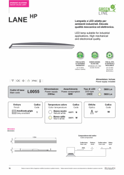
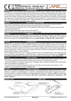
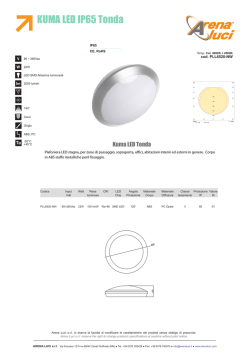
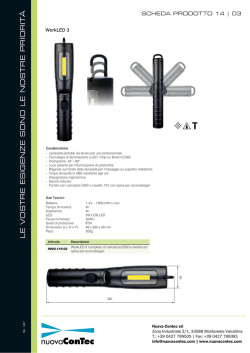
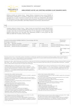
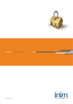
VISTA GENERALE
XDT200H
RIVELATORE DOPPIA TECNOLOGIA
XDT200H è un rivelatore infrarosso-microonda che utilizza un
elemento piroelettrico duale ed un sensore microonda perfetto
per l’uso professionale in applicazioni “indoor”.
Grazie ai due sensori e all’analisi digitale dei segnali XDT200H
coniuga una elevata sensibilità ad un’altrettanto elevata
immunità ai falsi allarmi. Sfruttando l’analisi digitale ed applicando una tecnica di
amplificazione e filtraggio del segnale estremamente innovativa e stabile, il dispositivo è
in grado di rilevare il movimento nell’area che è stato chiamato a presidiare con grande
affidabilità e precisione.
L’analisi digitale contempla anche una compensazione della temperatura per un
perfetto adattamento all'ambiente in cui il rivelatore è installato.
XDT200H può essere impiegato per un’ampia gamma di applicazioni che vanno dagli
ambienti residenziali a quelli commerciali.
XDT200H è anche facilmente configurabile con centrali antintrusione di marche
diverse e con diverse resistenze di fine linea (resistenze di bilanciamento). Infatti il
bilanciamento della linea è impostabile per mezzo delle resistenze di fine linea inseribili
negli appositi connettori a bordo del dispositivo.
CARATTERISTICHE PRINCIPALI
SPECIFICHE TECNICHE
Metodo d’installazione
Altezza d’installazione
Distanza di rilevamento (max)
Angolo di rilevamento
Uscita d’allarme
Uscita antimanomissione
LED verde
LED blu
LED giallo
Dimensioni (HxLxP)
Peso
Vista dall’alto
100°
RANGE DI RILEVAMENTO
Vista laterale
2.2
0
1.4
3.2
4.4
6.7
10
15
2
3
1
4
5
6
7
9
12
13
8
10
11
2
14
FUNZIONAMENTO
Le principali caratteristiche del rivelatore XDT200H sono:
• Analisi digitale dei segnali
• LED escludibili
• Copertura 15m
• 3 LED di segnalazione
• Angolo di rivelamento 100°
• Protezione antiapertura e antistrappo
• Conteggio degli impulsi
• Resistenze di fine linea
• Compensazione della temperatura
• Funzione AND/OR per generazione allarme
• Antiaccecamento
• Funzione “Smart-OR”
9V ÷ 16V dc
Tensione di alimentazione
20mA @ 12V dc
Corrente assorbita (max)
Temperatura di funzionamento 0°C ÷ +50°C
(14°F ÷ 122°F)
PIR duale digitale
Tipologia sensori
Sensore microonda
Emissione infrarossa
Modalità di rilevamento
+ effetto doppler
Strip-line con
Tipo di antenna
oscillatore FET-GaAs
10,525GHz
Frequenza microonda
1÷ 4
Impulsi d’allarme
Durata impulso relè d’allarme 5 secondi
1
CONNETTORI
fissaggio a muro
2.2m
15m
100°
N.C., 28V DC,
100mA max
N.C., 28V DC,
100mA max
Rilevamento MW
Segnale d’allarme
Rilevamento PIR
120x60x44mm
103g
• Fornendo l’alimentazione di 12V, i LED lampeggiano ed il rivelatore va in fase di auto-test.
• Entro 60s il rivelatore entra in stato operativo ed i LED si spengono. Il microinterruttore 6 sul DIP
switch abilita l'accensione dei LED.
Nota: Il microinterruttore 6 controlla il funzionamento dei LED e non influenza il funzionamento
del rivelatore.
• Se qualcuno si sta muovendo nello spazio coperto dal sensore, parte la segnalazione d’allarme
a seconda della modalità impostata. In tal caso il LED blu si accende ed il contatto di allarme si
apre per un tempo minimo di 5 secondi.
Funzione “AND/OR”: funzione per scegliere la modalità con cui XDT200H rileva l’allarme
● AND, i sensori PIR e MW rilevano il movimento contemporaneamente
● OR, uno dei due sensori rileva il movimento
Funzione “Smart-OR”: funzione che, se attivata e se il rivelatore è in modalità “AND”, fa
attivare il segnale di allarme anche quando uno solo dei due sensori rileva un movimento
di continuo per almeno 7 secondi.
• I microinterruttori 4 e 5 sul DIP switch impostano il numero minimo di impulsi rilevati per la
generazione dell'allarme (da 1 a 4).
• La temperatura ambientale influenza la capacità di rilevamento del sensore PIR.
Il sensore MW è invece influenzato da oggetti in movimento o vibranti.
Tramite gli appositi regolatori sul PCB è possibile regolare la sensibilità dei sensori:
● senso orario (+), aumento della sensibilità (massimo 15 m)
● senso antiorario (-), diminuzione della sensibilità (minimo 3 m)
• Ogni variazione della configurazione del DIP switch o della regolazione della sensibilità viene
segnalata dai LED con 3 lampeggi veloci.
INSTALLAZIONE
1. Scegliere una posizione idonea all’installazione.
2. Togliere la vite di bloccaggio del coperchio frontale ed aprire il coperchio divaricando le due
superfici dal lato della vite di bloccaggio.
3. Aprire i fori per il passaggio delle viti di ancoraggio, aprire i passacavi, inserire i cavi e fissare
la base del rivelatore con le viti di ancoraggio.
4. Inserire le resistenze EOL sui connettori a seconda del bilanciamento da effettuare.
5. Effettuare le connessioni alla morsettiera.
6. Configurare i microinterruttori sul DIP switch.
7. Regolare la sensibilità dei sensori.
15
8. Montare il coperchio frontale sulla base ed inserire la vite di bloccaggio.
Note: • L’altezza d’installazione raccomandata è di 2,2m.
• Prestare la massima attenzione per evitare di forare tubature, condotte del gas, canalizzazioni elettriche, ecc.
• Evitare di installare il rivelatore nelle vicinanze delle seguenti sorgenti di disturbo: superfici
riflettenti, flussi di aria diretta, spifferi, ventilatori, finestre, sorgenti di vapore, vapori d’olio,
sorgenti a raggi infrarossi, linee elettriche, lampade al neon ed oggetti che possono
causare variazioni di temperatura come stufe, frigoriferi e forni.
• Non installare più di un rivelatore XDT200H all’interno della stessa stanza o due rivelatori
XDT200H in stanze differenti ma ad una distanza inferiore ai 2m l’uno dall’altro rivelatore.
• Non posizionare oggetti di fronte al rivelatore.
• I LED devono essere al di sopra della lente.
+12V (1) - Positivo dell’alimentazione
-12V (2) - Negativo dell’alimentazione
ALARM (3-4) - Terminali di uscita per il
segnale di allarme
TAMPER (5-6) - Terminali di uscita per il
segnale di manomissione
RB1 - RB2 - RB3 - Connettori per
resistenze EOL
A - Contatto del segnale di allarme (N.C. a
riposo)
B - Contatto dell’antiapertura (N.C. a riposo)
C - Contatto dell’antistrappo (N.C. a riposo)
2
C
B
A
BILANCIAMENTI
La presente tabella dei bilanciamenti si riferisce alle centrali antintrusione della INIM
Electronics s.r.l. come ad esempio la SmartLiving.
Bilanciamento
RB3
/
/
6K8 Ω
/
Normalmente Chiuso
Bilanciamento singolo
Bilanciamento doppio
Bilanciamento
zona doppia
Bilanciamento
zona doppia con EOL
/
/
Contatti resistenze EOL
Terminali collegati
tra loro (ponticellati)
RB2
RB1
0 (corto)
/
/
6K8 Ω
/
/
6K8 Ω
/
4-5
/
3K9 Ω sensore1
4 sensore1 - 3 sensore2
6K8 Ω sensore2
0 (corto) sensore1 3K9 Ω sensore1 4 - 5 sensore1, 4 - 5 sensore2
3K9 Ω sensore2 6K8 Ω sensore2
6 sensore1 - 3 sensore2
DIP SWITCH
Microinterrutore
1
2
Modalità
allarme
Smart-OR
Funzione
ON - Modalità “OR”
OFF - Modalità “AND”
ON - Attiva
OFF - Disabilitata
3
Non usato
Microinterrutore
4
5
6
Funzione
Selezione numero di impulsi
1
2
3
4
OFF OFF ON
ON
OFF ON OFF
ON
Attivazione ON - LED attivati
LED
OFF - LED disattivati
AVVERTENZE
• Installare ed utilizzare il rivelatore attenendosi alle leggi e agli standard vigenti.
• Non toccare la superficie del sensore poiché tale operazione potrebbe causare il
malfunzionamento del rivelatore. Se necessario, pulire la superficie del sensore
utilizzando un panno soffice.
• L’utilizzatore deve seguire attentamente le istruzioni riportate in questa guida.
• Provare il prodotto periodicamente.
DICHIARAZIONE DI CONFORMITÀ
Deutsch: Hiermit erklärt Inim Electronics s.r.l., dass sich das Gerät XDT200H in Übereinstimmung mit den grundlegenden Anforderungen
und den übrigen einschlägigen Bestimmungen der Richtlinie 1999/5/EG befindet.
Български: С настоящето Inim Electronics s.r.l. декларира, че XDT200H отговаря на съществените изисквания и другите
приложими изисквания на Директива 1999/5/ЕС.
Ελληνικά: Ο εξοπλισμός αυτός συμμορφώνεται με την Ευρωπαική Οδηγία 1999/5/ΕΚ
Español: Por la presente, el INIM Electronics s.r.l declara que este "producto" cumple con la requisitos esenciales y otras disposiciones
relevantes de la Directiva 1999/5/CE.
Français: Par la présente, Inim Electronics s.r.l. déclare que l’appareil XDT200H est conforme aux exigences essentielles et aux autres
dispositions pertinentes de la directive 1999/5/CE.
Dansk: Undertegnede Inim Electronics s.r.l. erklærer herved, at følgende udstyr XDT200H overholder de væsentlige krav og øvrige
relevante krav i direktiv 1999/5/EF.
Magyar: Ez a berendezés megfelel az európai 1999/5/EC irányelvnek.
Malti: Hawnhekk, Inim Electronics s.r.l., jiddikjara li dan XDT200H jikkonforma mal-ħtiġijiet essenzjali u ma provvedimenti oħrajn relevanti
li hemm fi d-Dirrettiva 1999/5/EC.
Islenska: Hér með lýsir Inim Electronics yfi r því að XDT200H er í samræmi við grunnkröfur og aðrar kröfur, sem gerðar eru í tilskipun
1999/5/EC.
Italiano: Con la presente, Inim Electronics s.r.l. dichiara che questo XDT200H è con-forme ai requisiti essenziali ed alle altre disposizioni
pertinenti stabilite dalla direttiva 1999/5/CE.
La dichiarazione di conformità può essere consultata sul sito: www.inim.biz/certifications
via Fosso Antico, Centobuchi
63076 Monteprandone AP-Italy
tel +39 0735 705007
fax +39 0735 734912
Azienda certificata ISO 9001: 2008
[email protected]
ww.inim.biz
DCMIINIEXDT200H-R100-20140401
1) Passacavi
2) Sedi per viti di
fissaggio
3) Connettori per
resistenze EOL
4) Morsettiera
5) Sensore MW
6) LED
7) Contatto antiapertura
8) Vite di fissaggio PCB
9) Regolazione
sensibilità MW
10) Regolazione
sensibilità PIR
11) Antistrappo
12) Sensore PIR
13) DIP switch di
programmazione
14) Sede per vite di
bloccaggio
coperchio
GENERAL VIEW
DUAL TECHNOLOGY DETECTOR
The XDT200H Professional Series PIR and Microvawe
detector is especially suited for indoor applications.
Digital signal processing (DSP), a dual pyroelectric PIR
element and a microvawe sensor provide the XDT200H with a
perfect combination of high sensitivity and an ultra-low false alarm rate.
The powerful combination of digital signal processing and the latest extremely-stable
signal amplification and filtering technology allows this device to respond efficiently to
intrusion in the protected area and to deliver superior catch performance and precision.
DSP technology provides temperature compensation for perfect operation in the
protected area.
The XDT200H is suitable for a vast range of residential and commercial applications.
Trouble-free configuration allows easy installation with various brands of intrusion
control panels with diversified EOLR (balance resistance). This is the result of the
configurable line balance option which can be set by inserting the required EOL resistors
directly into the EOL connectors on-board the device.
MAIN FEATURES
The main features of the XDT200H are:
• Digital analysis of signals
• Detection range 15m
• Detection angle 100°
• Pulse count
• Automatic temperature compensation
• White light immunity
•
•
•
•
•
•
Bypassable LEDs
3 signalling LEDs
Anti-tamper and anti-dislodgement switches
End Of Line resistors
AND/OR function to trigger alarm
“Smart-OR” function
TECHNICAL SPECIFICATIONS
Supply voltage
Current draw (max)
Operating temperature
Sensor type
Detecting mode
Antenna type
MW frequency
Alarm pulses
Alarm relay pulse duration
9V to 16V dc
20mA @ 12V dc
0°C to +50°C
(14°F to 122°F)
digital dual PIR
microvawe sensor
infrared emission
+ doppler effect
plane antenna with
FET-GaAs oscillator
10.525GHz
1÷ 4
5 seconds
wall mount
2.2m
15m
100°
N.C., 28V DC,
100mA max
N.C., 28V DC,
100mA max
MW detection
alarm signal
PIR detection
120x60x44mm
103g
Installation method
Installation height
Detection range (max)
Detection angle
Alarm output
Tamper output
green LED
blue LED
yellow LED
Dimensions (HxLxD)
Weight
Top view
100°
DETECTION RANGE
Side view
2.2
0
1.4
3.2
4.4
6.7
10
15
1
2
3
CONNECTORS
1
4
5
6
7
9
12
13
8
10
11
2
14
OPERATING PRINCIPLES
• On first 12V power up, the LEDs will blink and the detector will initialise the auto-test phase.
• Within 60 seconds the detector will stabilise and become operational and the LEDs will go Off.
The microswitch 6 on the DIP switch enables the LEDs.
Note: The microswitch 6 influences the LEDs only, and in no way influences the functionality of
the detector.
• If motion is detected in the protected area, the detector will trigger the alarm signal depending
on AND/OR function, the blue LED will go On and the alarm contact will open for 5 seconds at
least.
“AND/OR” function: function to select the way XDT200H triggers alarm
● AND, PIR and MW sensors detect movement at the same time
● OR, one of the two sensors detects movement
“Smart-OR” function: : if this function is activated when the device is operating in “AND” mode,
the alarm signal will activate even when only one of the two detectors senses continuous
motion for at least 7 seconds.
• The microswitches 4 and 5 on the DIP switch are for alarm pulse number (from 1 to 4).
• The temperature in the protected area influences the performance of the PIR sensor.
The MW sensor detection is influenced by moving or vibrating objects.
The trimmers on-board the PCB will allow you to adjust detection sensitivity:
● clockwise (+) increases the sensitivity (maximum 15 m)
● anticlockwise (-) decreases the sensitivity (minimum 3 m)
• Any changes to the DIP switch configuration or any adjustments to detection sensitivity will be
signalled by three fast blinks on the device LEDs.
INSTALLATION
1. Choose a suitable mounting location.
2. Remove the retaining screw and detector cover.
3. Remove the wire-entry and wall-plug knockouts, pull the wires through the wire entry and,
using wall plugs, attach the mounting plate to the wall.
4. Insert the EOL resistors on the connectors depending on the requested balancing.
5. Complete the connections on the terminal board.
6. Configure the microswitches on the DIP switch.
7. Adjust the sensitivity of the sensors.
8. Replace the detector cover and tighten the retaining screw.
15
Notes:• Recommended installation height: 2.2m.
• Do not drill in the vicinity of electrical wiring or plumbing, etc.
• The detector should be located in place that is far from sources of interference, such as:
reflective surfaces, direct air flow, air-conditioning systems, windows, steam, oil vapour,
infrared sources, power lines, neon lamps and appliances which may cause temperature
changes (heaters, ovens, refrigerators, etc.).
• Only one detector XDT200H should be installed in each room. When installing XDT200H
detectors in different rooms, the detector placements should be at least 2 meters one from
the other.
• Ensure that no objects are placed in such way as to blind the detector.
• The LEDs should be located over the lens.
+12V (1) - Positive power supply
-12V (2) - Negative power supply
ALARM (3-4) - Alarm signal output terminals
TAMPER (5-6) - Tamper signal output
terminals
RB1 - RB2 - RB3 - EOL resistor
connectors
A - Alarm signal contact (N.C. during standby)
B - Open-tamper signal contact (N.C. during
standby)
C - Snatch-tamper signal contact (N.C. during
standby)
2
C
B
A
BALANCING
The following balancing table refers to INIM Electronics s.r.l. anti-intrusion control
panels, such as SmartLiving.
Balancing
Normally Closed
Single balancing
Double balancing
Double-zone
balancing
Double-zone
balancing with EOL
RB3
/
/
6K8 Ω
/
/
/
EOL resistor connectors
Terminals to be
short-circuited
RB2
RB1
0 (shorted)
/
/
6K8 Ω
/
/
6K8 Ω
/
4-5
/
3K9 Ω detector1
4 detector1 - 3 detector2
6K8 Ω detector2
0 (shorted) detector1 3K9 Ω detector1 4 - 5 detector1, 4 - 5 detector2
3K9 Ω detector2 6K8 Ω detector2
6 detector1 - 3 detector2
DIP SWITCH
Microswitch
1
2
Alarm
trigger
Smart-OR
3
Function
ON - “OR” mode
OFF - “AND” mode
ON - Function enabled
OFF - Function disabled
Microswitch
4
5
Not used
6
Function
Alarm pulse number selection
2
3
4
1
OFF OFF ON
ON
OFF ON OFF
ON
LED
ON - LEDs working
activation OFF - LEDs bypassed
WARNING
• This detector must be installed in compliance with the laws and standards in force.
• Do not touch the electronic components as this may damage the circuits and reduce
the reliability of the detector. If necessary, clean the detector with a soft cloth only.
• Install the detector strictly in accordance with the instructions in this leaflet.
• The device should be tested on a regular basis.
DECLARATION OF CONFORMITY
Lietuvių: Šiuo Inim Electronics s.r.l. deklaruoja, kad šis XDT200H atitinka esminius reikalavimus ir kitas 1999/5/EB Direktyvos nuostatas.
English: Hereby, Inim Electronics s.r.l., declares that this XDT200H is in compliance with the essential requirements and other relevant
provisions of Directive 1999/5/EC.
Nederlands: Hierbij verklaart Inim Electronics s.r.l. dat het toestel XDT200H in overeenstemming is met de essentiële eisen en de andere
relevante bepalingen van richtlijn 1999/5/EG.
Norsk: Inim Electronics s.r.l. erklærer herved at utstyret XDT200H er i samsvar med de grunnleggende krav og øvrige relevante krav I
direktiv 1999/5/EF.
Polski: Niniejszym Inim Electronics s.r.l. deklaruje że XDT200H jest zgodny z zasadniczymi wymaganiami i innymi właściwymi
postanowieniami Dyrektywy 1999/5/EC.
Português: Eu, Inim Electronics s.r.l., declaro que o XDT200H cumpre os requisitos essenciais e outras provisões relevantes da Directiva
1999/5/EC.
Româna: Prin prezenta, Inim Electronics s.r.l., declară că aparatul XDT200H este în conformitate cu cerinţele esenţiale şi cu alte prevederi
pertinente ale Directivei 1999/5/CE.
Svenska: Denna utrustning är i överensstämmelse med de väsentliga kraven och andra relevanta bestämmelser i Direktiv Försäkran om
över 1999/5/EC.
Slovenski: Inim Electronics s.r.l. izjavlja, da je ta XDT200H v skladu z bistvenimi zahtevami in drugimi relevantnimi določili direktive
1999/5/ES.
The declaration of conformity may be consulted at www.inim.biz/certifications
via Fosso Antico, Centobuchi
63076 Monteprandone AP-Italy
tel +39 0735 705007
fax +39 0735 734912
ISO 9001: 2008 registered company
[email protected]
ww.inim.biz
DCMIINIEXDT200H-R100-20140401
XDT200H
1) Wire-entry
2) Mounting screw
locations
3) EOL resistor
connectors
4) Terminal board
5) MW sensor
6) LEDs
7) Anti-opening tamper
8) PCB retaining screw
9) MW sensitivity
trimmer
10) PIR sensitivity
trimmer
11) Anti-snatch tamper
12) PIR sensor
13) Configuration DIP
switch
14) Cover retaining
screw location
© Copyright 2026 Paperzz