19798-6NL-03
PNOZ X2P
4
4
4
D
Betriebsanleitung
GB Operating instructions
F
Manuel d'utilisation
Sicherheitsbestimmungen
4
4
4
E
Instrucciones de uso
I
Istruzioni per l`uso
NL Gebruiksaanwijzing
Safety Regulations
Conseils préliminaires
• Das Gerät darf nur von Personen installiert
und in Betrieb genommen werden, die mit
dieser Betriebsanleitung und den geltenden Vorschriften über Arbeitssicherheit
und Unfallverhütung vertraut sind.
Beachten Sie die VDE- sowie die örtlichen
Vorschriften, insbesondere hinsichtlich
Schutzmaßnahmen.
• Beim Transport, der Lagerung und im
Betrieb die Bedingungen nach EN 600682-6 einhalten (s. technische Daten).
• Durch Öffnen des Gehäuses oder eigenmächtige Umbauten erlischt jegliche Gewährleistung.
• Montieren Sie das Gerät in einen Schaltschrank; Staub und Feuchtigkeit können
sonst zu Beeinträchtigungen der Funktionen führen.
• Sorgen Sie an allen Ausgangskontakten
bei kapazitiven und induktiven Lasten für
eine ausreichende Schutzbeschaltung.
• The unit may only be installed and
operated by personnel who are familiar
with both these instructions and the current
regulations for safety at work and accident
prevention. Follow VDE and local
regulations especially as regards
preventative measures.
• Transport, storage and operating conditions
should all conform to EN 60068-2-6.
• Any guarantee is void following opening of
the housing or unauthorised modifications.
• The unit should be panel mounted,
otherwise dampness or dust could lead to
function impairment.
• Adequate protection must be provided on
all output contacts especially with
capacitive and inductive loads.
• La mise en oeuvre de l’appareil doit être
effectuée par une personne spécialisée en
installations électriques, en tenant compte
des prescriptions des différentes normes
applicables (NF, EN, VDE...) notamment
au niveau des risques encourus en cas de
défaillance de l’équipement électrique.
• Respecter les exigences de la norme
EN 60068-2-6 lors du transport, du
stockage et de l'utilisation de l'appareil.
• L’ouverture de l’appareil ou sa modification
annule automatiquement la garantie.
• L’appareil doit être monté dans une armoire; l’humidité et la poussière pouvant
entraîner des aléas de fonctionnement.
• Vérifiez que le pouvoir de coupure des
contacts de sortie est suffisant en cas de
circuits capacitifs ou inductifs.
Bestimmungsgemäße Verwendung
Authorised Applications
Domaines d’utilisation
Das Sicherheitsschaltgerät dient dem
sicherheitsgerichteten Unterbrechen eines
Sicherheitsstromkreises.
Das Sicherheitsschaltgerät erfüllt Forderungen der EN 60947-5-1, EN 60204-1 und
VDE 0113-1 und darf eingesetzt werden in
Anwendungen mit
• Not-Halt-Tastern
• Schutztüren
The safety relay provides a safety-related
interruption of a safety circuit.
The safety relay meets the requirements of
EN 60947-5-1, EN 60204-1 and VDE 0113-1
and may be used in applications with
• E-STOP pushbuttons
• Safety gates
Le bloc logique de sécurité sert à interrompre
en toute sécurité un circuit de sécurité.
Le bloc logique de sécurité satisfait aux
exigences des normes EN 60947-5-1,
EN 60204-1 et VDE 0113-1 et peut être
utilisé dans des applications avec des
• poussoirs d’arrêt d’urgence
• protecteurs mobiles
Gerätebeschreibung
Description
Description de l’appareil
Das Sicherheitsschaltgerät PNOZ X2P ist in
einem S-99-Gehäuse untergebracht. Es
kann mit 24 V Wechsel- oder Gleichspannung oder mit 48 ... 240 V Wechseloder Gleichspannung betrieben werden.
Merkmale:
• Relaisausgänge: 2 Sicherheitskontakte
(Schließer), zwangsgeführt
• Anschlussmöglichkeit für Not-Halt-Taster,
Schutztürgrenztaster und Starttaster
• Statusanzeige
• Überwachung externer Schütze möglich
• 24 V AC/DC: keine galvanische Trennung
• 48 ... 240 V AC/DC: galvanisch getrennt
The Safety Relay PNOZ X2P is enclosed in a
S-99 housing. The unit can be operated with
24 V AC/DC or with 48 ... 240 V AC/DC.
Features:
• Relay outputs: 2 safety contacts (N/O),
positive-guided
• Connections for Emergency Stop Button,
Safety Gate Limit Switch and Reset button
• Status Indicators
• Feedback Control Loop for monitoring of
external contactors/relays possible
• 24 V AC/DC: No galvanic separation
• 48 ... 240 V AC/DC: galvanic separation
Inséré dans un boîtier S-99, le bloc logique
de sécurité PNOZ X2P peut être alimenté en
24 V AC/DC ou en 48 ... 240 V AC/DC.
Particularités :
• Sorties disponibles : 2 contacts à
fermeture de sécurité
• Bornes de raccordement pour poussoirs
AU, détecteurs de position et poussoir de
validation
• LEDs de visualisation
• Auto-contrôle des contacteurs externes
possible
• 24 V AC/DC: pas d'isolation galvanique
• 48 ... 240 V AC/DC: d'isolation galvanique
Das Schaltgerät erfüllt folgende Sicherheitsanforderungen:
• Schaltung ist redundant mit Selbstüberwachung aufgebaut.
• Sicherheitseinrichtung bleibt auch bei Ausfall eines Bauteils wirksam.
• Bei jedem Ein-Aus-Zyklus der Maschine
wird automatisch überprüft, ob die Relais
der Sicherheitseinrichtung richtig öffnen
und schließen.
The relay complies with the following safety
requirements:
• The circuit is redundant with built-in selfmonitoring.
• The safety function remains effective in the
case of a component failure.
• The correct opening and closing of the
safety function relays is tested
automatically in each on-off cycle.
Le relais PNOZ X2P répond aux exigences
suivantes :
• conception redondante avec autosurveillance
• sécurité garantie même en cas de
défaillance d’un composant
• test cyclique (ouverture/fermeture des
relais internes) à chaque cycle Marche/
Arrêt de la machine
-1-
Funktionsbeschreibung
Function Description
Description du fonctionnement
Das Schaltgerät PNOZ X2P dient dem
sicherheitsgerichteten Unterbrechen eines
Sicherheitsstromkreises. Nach Anlegen der
Versorgungsspannung leuchtet die LED
"POWER". Das Gerät ist betriebsbereit, wenn
der Startkreis S33-S34 geschlossen ist.
• Eingangskreis geschlossen (z. B. Not-HaltTaster nicht betätigt):
Relais K1 und K2 gehen in Wirkstellung und
halten sich selbst. Die Statusanzeigen für
"CH.1" und "CH.2" leuchten. Die Sicherheitskontakte 13-14/23-24 sind geschlossen.
• Eingangskreis wird geöffnet (z. B. Not-HaltTaster betätigt):
Relais K1 und K2 fallen in die Ruhestellung
zurück. Die Statusanzeige für "CH.1" und
"CH.2" erlischt. Die Sicherheitskontakte
13-14/23-24 werden redundant geöffnet.
The relay PNOZ X2P provides a safetyoriented interruption of a safety circuit. When
the operating voltage is supplied the LED
"POWER" is illuminated. The unit is ready
for operation, when the reset circuit S33-S34
is closed.
• Input Circuit closed (e.g. the Emergency
Stop button is not pressed):
Relays K1and K2 energise and retain
themselves. The status indicators for
"CH.1" and "CH.2" illuminate. The safety
contacts (13-14/23-24) are closed.
• Input Circuit is opened (e.g. Emergency
Stop is pressed):
Relays K1 and K2 de-energise. The status
indicators for "CH.1" and "CH.2" go out.
The safety contacts (13-14/23-24) will be
opened (redundant).
Le relais PNOZ X2P assure de façon sure,
l’ouverture d’un circuit de sécurité. A la mise
sous tension du relais (A1-A2), la LED
"POWER" s'allume. Le relais est activé si le
circuit de réarmement S33-S34 est fermé.
• Circuits d'entrée fermés (poussoir AU non
actionné) :
Les relais K1 et K2 passent en position
travail et s'auto-maintiennent. Les LEDs
"CH.1" et CH.2" s'allument. Les contacts
de sécurité (13-14/23-24) sont fermés.
• Circuits d'entrée ouverts (poussoir AU
actionné) :
Les relais K1 et K2 retombent. Les LEDs
"CH.1" et "CH.2" s'éteingnent. Les
contacts de sécurité (13-14/23) s'ouvrent.
UB = 24 V DC, 24 V AC
A1 (L+)
A2 (L-) Y36 Y37
UB = 48 ... 240 V AC/DC
S34 S33 S11 S12
Start
Unit
A1 (L+) A2 (L-)
13 23
Y36 Y37
K1
Auto
Start
Start
Unit
13 23
K1
AC/DC
Start
Unit
S22
S34 S33 S11 S12
S21
DC
K2
Auto
Start
Start
Unit
S22
14 24
S21
K2
14 24
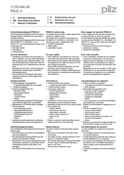
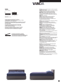
Fig. 1: Innenschaltbild/Internal Wiring Diagram/Schéma de principe
Betriebsarten:
• Einkanaliger Betrieb (nur PNOZ X2P,
24 V AC/DC): Eingangsbeschaltung nach
VDE 0113 Teil 1 und EN 60204-1; keine
Redundanz im Eingangskreis; Erdschlüsse
im Startkreis werden erkannt.
• Zweikanaliger Betrieb: redundanter Eingangskreis, Erdschlüsse im Tasterkreis
und Querschlüsse zwischen den Tasterkontakten werden erkannt.
• Automatischer Start: Gerät ist aktiv, sobald
Eingangskreis geschlossen ist.
• Manueller Start: Gerät ist erst dann aktiv,
wenn ein Starttaster betätigt wird. Dadurch
ist ein automatischer Start des Schaltgeräts nach Spannungsausfall und wiederkehr ausgeschlossen.
• Überwachter Start: Gerät ist nur aktiv,
wenn vor dem Schließen des Eingangskreises der Startkreis geöffnet wird und
mindestens 180 ms nach dem Schließen
des Eingangskreises der Startkreis
geschlossen wird.
• Kontaktvervielfachung und -verstärkung
durch Anschluss von externen Schützen
Operating Modes
• Single-channel operation (only PNOZ
X2P, 24 V AC/DC: Input wiring according
to VDE 0113 part 1 and EN 60204-1, no
redundancy in the input circuit. Earth faults
are detected in the reset circuit.
• Two-channel operation: Redundancy in
the input circuit. Earth faults in the
Emergency Stop circuit and shorts across
the emergency stop push button are also
detected.
• Automatic reset: Unit is active as soon as
the input circuit is closed.
• Manual reset: Unit is only active when a
reset button has been pressed.
Automatic activation following a loss/return
of supply voltage is thereby prevented.
• Monitored manual reset: The unit is only
active if, the reset circuit is opened before
closing the safety input circuit and then the
reset circuit is closed at least 180 ms after
closing the safety input circuit.
• Increase in the number of available
contacts by connection of external
contactors/relays.
Modes de fonctionnement
• Commande par 1 canal (PNOZ X2P,
24 V AC/DC uniquement): conforme aux
prescriptions de la EN 60204/1, pas de
redondance dans le circuit d’entrée. La
mise à la terre du circuit de réarmement
est détectée.
• Commande par 2 canaux: circuit d’entrée
redondant. La mise à la terre et les courtscircuits entre les contacts sont détectées.
• Réarmement automatique : le relais est
activé dès la fermeture des canaux
d’entrée.
• Réarmement manuel : le relais n’est activé
qu’après une impulsion sur un poussoir de
validation. Un réarmement automatique du
relais après une coupure d’alimentation
est ainsi impossible.
• Réarmement manuel auto-contrôlé: le
relais n’est réarmé que si le circuit de
réarmement est ouvert avant la fermeture
du circuit d’entrée, puis refermé au min.
180 ms après la fermeture du circuit
d’entrée.
• Augmentation du nombre de contacts ou
du pouvoir de coupure par l’utilisation de
contacteurs externes.
Montage
Installation
Montage
Das Sicherheitsschaltgerät muss in einen
Schaltschrank mit einer Schutzart von mind.
IP54 eingebaut werden. Zur Befestigung auf
einer Normschiene dient ein Rastelement auf
der Rückseite des Geräts.
Sichern Sie das Gerät bei Montage auf einer
senkrechten Tragschiene (35 mm) durch ein
Halteelement wie z. B. Endhalter oder
Endwinkel.
The safety relay must be panel mounted
(min. IP54). There is a notch on the rear of
the unit for DIN-Rail attachment.
If the unit is installed on a vertical mounting
rail (35 mm), ensure it is secured using a
fixing bracket such as end bracket.
Le relais doit être monté en armoire ayant un
indice de protection mini IP54. Sa face
arrière permet un montage sur rail DIN.
Immobilisez l'appareil monté sur un rail DIN
vertical (35 mm) à l'aide d'un élément de
maintien comme par ex. un support ou une
équerre terminale.
-2-
Inbetriebnahme
Operation
Mise en oeuvre
Beachten Sie bei der Inbetriebnahme:
• Vor die Ausgangskontakte eine
Sicherung (s. techn. Daten) schalten,
um das Verschweißen der Kontakte zu
verhindern.
• Berechnung der max. Leitungslänge Imax im
Eingangskreis:
Please note for operation:
• To prevent a welding together of the
contacts, a fuse (see technical detail)
must be connected before the output
contacts.
• Calculate the max. Cable runs Imax in the
input circuit:
Remarques préliminaires :
• Raccordez un fusible (voir les
caractéristiques techniques) avant les
contacts de sortie afin d’éliminer tout
risque de fusion.
• Calcular les longueurs de câblage max Imax
dans le circuit d’entrée:
Imax =
•
•
•
•
Rlmax
Imax =
Rl / km
Rlmax = max. Gesamtleitungswiderstand (s. technische Daten)
Rl /km = Leitungswiderstand/km
Da die Funktion Querschlusserkennung
nicht einfehlersicher ist, wird sie von Pilz
während der Endkontrolle geprüft. Eine
Überprüfung nach der Installation des
Geräts ist wie folgt möglich:
1. Gerät betriebsbereit (Ausgangskontakte
geschlossen)
2. Die Testklemmen S12-S22 zur
Querschlussprüfung kurzschließen.
3. Die Sicherung im Gerät muss auslösen
und die Ausgangskontakte öffnen.
Leitungslängen in der Größenordnung der
Maximallänge können das Auslösen der
Sicherung um bis zu 2 Minuten verzögern.
Bei Querschluss kann die
LED "POWER" bei der Gerätevariante
PNOZ X2P 48 ... 240 V AC/DC weiterleuchten.
4. Sicherung wieder zurücksetzen: den
Kurzschluss entfernen und die Versorgungsspannung für ca. 1 Minute abschalten.
Leitungsmaterial aus Kupferdraht mit einer
Temperaturbeständigkeit von 60/75 °C
verwenden.
Sorgen Sie beim Anschluss von magnetisch wirkenden, auf Reedkontakten
basierenden Näherungsschaltern dafür,
dass der max. Einschaltspitzenstrom (am
Eingangskreis) den Näherungsschalter
nicht überlastet.
Angaben im Kapitel „Technische Daten“
unbedingt einhalten.
Ablauf:
• Versorgungsspannung an Klemmen A1 und
A2 anlegen.
• Versorgungsspannung 48 ... 240 V AC/DC:
Betriebserdungsklemme mit Schutzleitersystem verbinden.
• Startkreis:
- Automatischer Start: S33-S34 und Y36Y37 brücken.
- Manueller Start: Taster an S33-S34
anschließen und Y36-Y37 brücken.
- Überwachter Start: Taster an S33-S34
anschließen.
• Eingangskreis:
- Einkanalig (nur PNOZ X2P mit 24 V AC/
DC):
Öffnerkontakt von Auslöseelement
zwischen Plusklemme (L+) der Versorgungsspannung und Klemme A1
anschließen, S11-S12 und S21-S22
brücken.
- Zweikanalig: Öffnerkontakt von Auslöseelement an S11-S12 und S21-S22
anschließen.
• Rückführkreis:
Externe Schütze in Reihe zu Startkreis
S33-S34 anschließen.
Die Sicherheitskontakte sind aktiviert (geschlossen). Die Statusanzeigen für "CH.1",
"CH.2" leuchten. Das Gerät ist betriebsbereit.
Wird der Eingangskreis geöffnet, öffnen die
Sicherheitskontakte 13-14/23-24. Die
Statusanzeige erlischt.
•
•
•
•
Rlmax
Imax =
Rl / km
Rlmax = Max. Total cable resistance
(see technical details)
Rl /km = Cable resistance/km
As the function for detecting shorts across
the inputs is not failsafe, it is tested by Pilz
during the final control check. However, a
test is possible after installing the unit and
it can be carried out as follows:
1. Unit ready for operation (output contacts
closed)
2. Short circuit the test (connection)
terminals S12-S22 for detecting shorts
across the inputs.
3. The unit‘s fuse must be triggered and
the output contacts must open. Cable
lengths in the scale of the maximum length
can delay the fuse triggering for up to 2
minutes.
On the PNOZ X2P 48 ... 240 V AC/DC,
the „POWER“ LED may stay lit when
there is a short across the inputs.
4. Reset the fuse: remove the short circuit
and switch off the operating voltage for
approx. 1 minute.
Use copper wiring that will withstand
60/75 °C.
When connecting magnetically operated,
reed proximity switches, ensure that the
max. peak inrush current (on the input
circuit) does not overload the proximity
switch.
Important details in the section "Technical
Data“ should be noted and adhered to.
To operate:
• Connect the operating voltage to terminals
A1 and A2.
• Operating Voltage 48 ... 240 V AC/DC:
Connect the operating earth terminal
with the ground earth.
• Reset circuit:
- Automatic reset: Bridge S33-S34 and
Y36-Y37.
- Manual reset: Connect button to S33S34 and bridge Y36-Y37.
- Monitored manual reset: Connect button
to S33-S34.
• Input circuit:
- Single-channel (only PNOZ X2P, 24 V
AC/DC:
Connect N/C contact from safety switch
between the positive terminal (L+) of
the operating voltage and terminal A1,
link S11-S12 and S21-S22.
- Two-channel: Connect N/C contact from
safety switch (e.g. Emergency-Stop) to
S11-S12 and S21-S22.
• Feedback control loop:
Connect external contactors/relays in
series with reset circuit S33-S34.
The safety contacts are activated (closed).
The status indicators "CH.1" and "CH.2" are
illuminated. The unit is ready for operation. If
the input circuit is opened, the safety
contacts 13-14/23-24 open. The status
indicator goes out.
-3-
•
•
•
•
Rlmax
Rl / km
Rlmax = résistivité de câblage totale max.
(voir les caractéristiques techniques)
Rl /km = résistivité de câblage/km
La fonction de détection de court-circuit est
testé par Pilz lors du contrôle final. Un test
sur site est possible de la façon suivante :
1. Appareil en fonction (contacts de sortie
fermés)
2. Court-circuiter les bornes de
raccordement nécessaires au test S12S22
3. Le fusible interne du relais doit
déclencher et les contacts de sortie
doivent s‘ouvrir. Le temps de réponse du
fuisible peut aller jusqu‘à 2 min. si les
longueurs de câblage sont proches des
valeurs maximales.
La LED „Power“ peut rester allumée en
cas de court-cirucit sur les variantes
PNOZ X2P 48 ... 240 V AC/DC.
4. Réarmement du fusible : enlever le
court-circuit et couper l‘alimentation du
relais pendant au moins 1 min.
Utiliser uniquement des fils de cablâge en
cuivre 60/75 °C.
Lors du raccordement de détecteurs de
proximité magnétiques, basés sur des
contacts Reed, veuillez vous assurer que
le courant de crête max. à la mise sous
tension (sur le circuit d'entrée) ne
surcharge pas les détecteurs de proximité.
Respecter les données indiquées dans le
chap. „Caractéristiques techniques“.
Mise en oeuvre :
• Amener la tension d’alimentation sur A1
et A2.
• Tension d’alimentation 48 ... 240 V AC/DC:
relier la borne terre
• Circuit de réarmement:
- Réarmement automatique: pontage des
bornes S33-S34 et Y36-Y37
- Réarmement manuel : câblage d'un
poussoir sur S33-S34 et pontage des
bornes Y36-Y37
- Réarmement manuel auto-contrôlé:
câblage d'un poussoir sur S33-S34
• Circuits d’entrée:
- Commande par 1 canal (PNOZ X2P,
24 V AC/DC uniquement):
câblage du contact à ouverture entre le
potentiel (L+) de la tension
d'alimentation et la borne A1 (+),
pontage entre S11-S12 et S21-S22
- Commande par 2 canaux: câblage des
contacts à ouverture entre S11-S12 et
S21-S22
• Boucle de retour:
Câblage en série des contacts externes
dans le circuit de rèarmement S33-S34
Les contacts de sécurité se ferment. Les
LEDs "CH.1" et "CH.2" sont allumées.
L’appareil est prêt à fonctionner.
Si le circuit d’entrée est ouvert, les contacts
de sécurité retombent. Les LEDs
s’éteignent.
Wieder aktivieren
• Eingangskreis schließen.
• Bei manuellem Start zusätzlich Taster
zwischen S33 und S34 betätigen.
Die Statusanzeigen leuchten wieder, die
Sicherheitskontakte sind geschlossen.
Reactivation
• Close the input circuit.
• For manual reset press the button between
S33-S34.
The status indicators illuminate once more,
the safety contacts are closed.
Remise en route :
• fermer le circuit d’entrée
• en cas de réarmement manuel, appuyer
sur le poussoir de validation entre S33S34.
Les LEDs sont à nouveau allumées. Les
contacts de sécurité sont fermées.
Anwendung
Application
Utilisation
In Fig. 2 ... Fig. 6 sind Anschlussbeispiele für
Not-Halt-Beschaltung mit automatischem und
überwachtem Start, Schutztüransteuerungen sowie Kontaktvervielfachung durch
externe Schütze.
Beachten Sie bei Fig. 4: Das Gerät startet
bei Spannungsausfall und -wiederkehr
automatisch. Verhindern Sie einen unerwarteten Wiederanlauf durch externe
Schaltungsmaßnahmen.
In Fig. 2...Fig. 6 are connection examples for
Emergency Stop wiring with automatic and
monitored manual reset. Safety gate control
as well as contact expansion via external
contactors.
Please note for Fig. 4: the device starts
automatically after loss of power. You should
prevent an unintended start-up by using
external circuitry measures.
Dans les figures 2 à 6 sont représentés les
différents cablages possibles du PNOZ X2P :
poussoirs AU avec réarmement automatique et
surveillance du circuit de réarmement,
interrupteur de position et augmentation du
nombre des contacts par contacteurs externes.
Dans le cas de la figure 4, l’appareil se
réarme automatiquement après une coupure
et une remise sous tension. Evitez tout
risque de redémarrage par un câblage
externe approprié.
S33
S11 S21
S11
S33
S11 S21
UB
(L+)
S33
Y36
S34
Y37
S1
S1
S1
S3
S12
S21
S3
S2
A1 S12 S22
S34
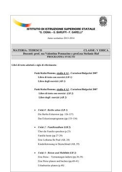
Fig. 2: nur bei PNOZ X2P, 24 V AC/DC:
Eingangskreis einkanalig, überwachter Start/
only PNOZ X2P, 24 V AC/DC:Singlechannel input circuit, monitored manual reset/
PNOZ X2P, 24 V AC/DC uniquement:
Commande par 2 canal, réarmement manuel
auto-contrôlé
S11
S12 S22
S22
Fig. 3: Eingangskreis zweikanalig,
überwachter Start /Two-channel input
circuit, monitored manual reset/Commande
par 2 canaux, réarmement manuel autocontrôlé
K4
S33
K5
S34 13
betätigtes Element/Switch activated/
élément actionné
S12 S3
S21
Tür nicht geschlossen/Gate open/
porte ouverte
S2
14
K4
S22
S34
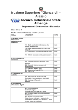
Fig. 4: Schutztürsteuerung zweikanalig,
automatischer Start/Dual-channel safety gate
control, automatic reset/Surveillance de
protecteur, commande par 2 canaux,
réarmement automatique
L1
S33
S1
S34
K5
Tür geschlossen/Gate closed/porte
fermée
N
Fig. 6: Anschlussbeispiel für externe
Schütze, einkanalig/Connection example for
external contactors/relays, single-channel/
Branchement contacteurs externes,
commande par 1 canal
S1/S2: Not-Halt- bzw. Schutztürschalter/
Emergency Stop Button, Safety
Gate Limit Switch/Poussoir AU,
détecteurs de position
S3:
Starttaster/Reset button/Poussoir
de réarmement
Fehler - Störungen
Faults
Erreurs - Défaillances
• Erdschluss
Die Versorgungsspannung bricht zusammen
und die Sicherheitskontakte werden über eine
elektronische Sicherung geöffnet. Nach
Wegfall der Störungsursache und Abschalten
der Versorgungsspannung für ca. 1 Minute ist
das Gerät wieder betriebsbereit.
• Bei Querschluss kann die LED "POWER" bei
der Gerätevariante PNOZ X2P
48 ... 240 V AC/DC weiterleuchten.
• Fehlfunktionen der Kontakte: Bei verschweißten Kontakten ist nach Öffnen des Eingangskreises keine neue Aktivierung möglich.
• LED "POWER" leuchtet nicht: Kurzschluss
oder fehlende Versorgungsspannung.
• Earth fault
Supply voltage fails and the safety
contacts are opened via an electronic fuse.
Once the cause of the fault has been
removed and operating voltage is switched
off, the unit will be ready for operation after
approximately 1 minute.
• On the PNOZ X2P 48 ... 240 V AC/DC, the
„POWER“ LED may stay lit when there is a
short across the inputs.
• Contact failure: In the case of welded
contacts, no further activation is possible
following an opening of the input circuit.
• LED "POWER" is not illuminated if shortcircuit or the supply voltage is lost.
• Défaut de masse
La tension d’alimentation chute et les contacts
de sécurité sont ouverts par un fusible
électronique. Une fois la cause du défaut
éliminée et la tension d’alimentation coupée,
l’appareil est à nouveau prêt à fonctionner
après environ 1 minute.
• La LED „Power“ peut rester allumée en cas de
court-cirucit sur les variantes
PNOZ X2P 48 ... 240 V AC/AC.
• Défaut de fonctionnement des contacts de
sortie: en cas de soudage d’un contact lors de
l’ouverture du circuit d’entrée, un nouvel
réarmement est impossible.
• LED "POWER" éteinte: tension d'alimentation
non présente ou court-circuit interne.
Fig. 5: Schutztürsteuerung zweikanalig,
überwachter Start /Dual-channel safety gate
control, monitored manual reset/Surveillance
de protecteur, commande par 2 canaux,
réarmement manuel auto-contrôlé
-4-
Technische Daten
Technical Data
Caractéristiques techniques
Elektrische Daten
Versorgungsspannung UB
Electrical data
Supply Voltage UB
Données électriques
Tension d’alimentation UB
Spannungstoleranz
Leistungsaufnahme bei UB
Voltage Tolerance
Power consumption at UB
Plage de la tension d’alimentation
Consommation pour UB
Frequenzbereich
Restwelligkeit
Spannung und Strom an
Eingangskreis
UB = 24 V AC/DC:
UB = 48 ... 240 V AC/DC:
Start- und Rückführkreis
Frequency Range
Residual Ripple
Voltage and Current at
Input circuit
UB = 24 V AC/DC:
UB = 48 ... 240 V AC/DC:
Reset circuit and feedback loop
UB = 24 V AC/DC:
UB = 48 ... 240 V AC/DC:
Anzahl der Ausgangskontakte
Sicherheitskontakte (S)
Gebrauchskategorie nach
EN 60947-4-1
UB = 24 V AC/DC:
UB = 48 ... 240 V AC/DC:
Number of output contacts
Safety contacts (N/O)
Utilization category in accordance with
EN 60947-4-1
Fréquence
Ondulation résiduelle
Tension et courant du
Circuit d’entrée
UB = 24 V AC/DC:
UB = 48 ... 240 V AC/DC:
Circuit de réarmement et boucle
de retour
UB = 24 V AC/DC:
UB = 48 ... 240 V AC/DC:
Nombre de contacts de sortie
contacts de sécurité (F)
Catégorie d’utilisation selon
EN 60947-4-1
EN 60947-5-1(DC13:
6 Schaltspiele/Min.)
Kontaktmaterial
Kontaktabsicherung extern
EN 60947-5-1 (IK = 1 kA)
Schmelzsicherung flink
Schmelzsicherung träge
Sicherungsautomat
Charakteristik
Max. Gesamtleitungswiderstand Rlmax
Eingangskreise
UB = 24 V AC/DC
einkanalig DC
einkanalig AC
zweikanalig mit
Querschlusserkennung DC
zweikanalig mit
Querschlusserkennung AC
UB = 48 ... 240 V AC/DC
einkanalig DC
einkanalig AC
zweikanalig mit
Querschlusserkennung DC
zweikanalig mit
Querschlusserkennung AC
Min. Eingangswiderstand im Einschaltmoment
UB = 24 V AC/DC:
UB = 48 ... 240 V AC/DC:
Sicherheitstechnische Kenndaten
der Sicherheitsausgänge
PL nach EN ISO 13849-1
Kategorie nach EN 954-1
SIL CL nach EN IEC 62061
PFH nach EN IEC 62061
SIL nach IEC 61511
PFD nach IEC 61511
tM in Jahren
Zeiten
Einschaltverzögerung
UB = 24 V AC/DC
Automatischer Start
Manueller Start
Überwachter Start
UB = 48 ... 240 V AC/DC
Automatischer Start
Manueller Start
Überwachter Start
EN 60947-5-1(DC13: 6 cycles/min)
Contact material
External contact fuse protection
EN 60947-5-1 (IK = 1 kA)
Blow-out fuse quick
Blow-out fuse slow
Safety cut-out
Cvaracteristic
Max. overall cable resistance Rlmax
input circuits
UB = 24 V AC/DC
Single-channel DC
Single-channel AC
Dual-channel with detection of
shorts across contacts DC
Dual-channel with detection of
shorts across contacts AC
UB = 48 ... 240 V AC/DC
Single-channel DC
Single-channel AC
Dual-channel with detection of
shorts across contacts DC
Dual-channel with detection of
shorts across contacts AC
Min. input resistance in the starting
torque
UB = 24 V AC/DC:
UB = 48 ... 240 V AC/DC:
Safety-related characteristics of
the safety outputs
PL in accordance with
EN ISO 13849-1
Category in accordance with
EN 954-1
SIL CL in accordance with
EN IEC 62061
PFH in accordance with
EN IEC 62061
SIL in accordance with IEC 61511
PFD in accordance with IEC 61511
tM in years
Times
Switch-on delay
UB = 24 V AC/DC
Automatic reset
Manual reset
Monitored manual reset
UB = 48 ... 240 V AC/DC
Automatic reset
Manual reset
Monitored manual reset
-5-
EN 60947-5-1(DC13:
6 manoeuvres/min)
Matériau contact
Protection des contacts externe
EN 60947-5-1 (IK = 1 kA)
Fusibles rapide
Fusibles normal
Dijoncteur
Caractéristique
Résistance de câblage totale max.
Rlmax circuits d'entrée
UB = 24 V AC/DC
Commande par 1 canal DC
Commande par 1 canal AC
Commande par 2 canaux avec
détection des court-circuits DC
Commande par 2 canaux avec
détection des court-circuits AC
UB = 48 ... 240 V AC/DC
Commande par 1 canal DC
Commande par 1 canal AC
Commande par 2 canaux avec
détection des court-circuits DC
Commande par 2 canaux avec
détection des court-circuits AC
Résistance d'entrée min. au moment
de la mise en marche
UB = 24 V AC/DC:
UB = 48 ... 240 V AC/DC:
Caractéristiques techniques de
sécurité des sorties de sécurité
PL selon EN ISO 13849-1
24 V AC/DC
48 ... 240 V AC/DC
-15 ... +10 %
UB = 24 V AC: 4,5 VA;
UB = 24 V DC: 2,0 W
UB = 48 ... 240 V AC: 3,5 VA;
UB = 48 ... 240 V DC: 1,0 W
50 ... 60 Hz
DC: 160 %
24 V DC/25 mA
24 V DC/15 mA
24 V DC/50 mA
24 V DC/25 mA
2
AC1: 240 V/0,01 ... 6 A/
1500 VA
DC1: 24 V/0,01 ... 6 A/
150 W
AC15: 230 V/5 A;
DC13: 24 V/4 A
AgSnO2+ 0,2 µm Au
6A
4A
24 V AC/DC: 4 A
B/C
150 Ohm
50 Ohm
15 Ohm
30 Ohm
100 Ohm
100 Ohm
100 Ohm
100 Ohm
21 Ohm
19 Ohm
PL e (Cat. 4)
Catégorie selon EN 954-1
Cat. 4
SIL CL selon EN IEC 62061
SIL CL 3
PFH selon EN IEC 62061
SIL selon IEC 61511
PFD selon IEC 61511
tM en années
Temporisations
Temps de réarmement
UB = 24 V AC/DC
Réarmement automatique
Réarmement manuel
Réarmement manuel auto-contrôlé
UB = 48 ... 240 V AC/DC
Réarmement automatique
Réarmement manuel
Réarmement manuel auto-contrôlé
2,31E-09
SIL 3
2,03E-06
20
typ. 60 ms, max. 90 ms
typ. 38 ms, max. 90 ms
typ. 38 ms, max. 50 ms
typ. 120 ms, max. 150 ms
typ. 38 ms, max. 150 ms
typ. 38 ms, max. 50 ms
Rückfallverzögerung
UB = 24 V AC/DC
bei Not-Halt, zweikanalig
Delay-on De-Energisation
UB = 24 V AC/DC
at E-STOP, two-channel
Temps de retombée
UB = 24 V AC/DC
en cas d'arrêt d'urgence,
commande par 2 canaux
typ.: 17 ms, max.: 30 ms
bei Netzausfall oder Not-Halt,
with power failure or E-STOP, sinen cas de coupure d'alimentation ou
einkanalig
gle-channel
cas d'arrêt d'urgence, commande
par 1canal
typ.: 70 ms, max.: 110 ms
UB = 48 ... 240 V AC/DC
UB = 48 ... 240 V AC/DC
UB = 48 ... 240 V AC/DC
bei Not-Halt
at E-STOP
en cas d'arrêt d'urgence
typ.: 12 ms, max.: 30 ms
bei Netzausfall
with power failure
en cas de coupure d'alimentation 48 V: typ.: 40 ms,
max.: 70 ms
240 V: typ.: 320 ms,
max.: 500 ms
Wiederbereitschaftszeit bei max.
Recovery time at max. switching
Temps de remise en service en cas de
Schaltfrequenz 1/s
frequency 1/s
fréquence de commutation max. 1/s
nach Not-Halt
after E-STOP
arrêt d'urgence
50 ms
nach Netzausfall
after power failure
après une coupure d'alimentation UB = 24 V AC/DC: 150 ms
UB = 48 ... 240 V AC/DC:
550 ms
Wartezeit bei überwachtem Start
Waiting period on monitored reset
Temps d’attente en cas d’un
180 ms
démarrage surveillé
Gleichzeitigkeit Kanal 1 und 2
Simultaneity channel 1 and 2
Désynchronisme canal 1 et 2
∞
Überbrückung bei
Supply interruption before deTenue aux micro-coupures
Spannungseinbrüchen
energisation
20 ms
Umweltdaten
Environmental data
Données sur l'environnement
EN 60947-5-1,
EMV
EMC
CEM
EN 61000-6-2,
EN 61000-6-3
Schwingungen nach EN 60068-2-6 Vibration to EN 60068-2-6
Vibrations selon EN 60068-2-6
Frequenz
Frequency
Frequence
10 ... 55 Hz
Amplitude
Amplitude
Amplitude
0,35 mm
Klimabeanspruchung
Climate Suitability
Conditions climatiques
EN 60068-2-78
Luft- und Kriechstrecken nach
Airgap Creepage in accordance with Cheminement et claquage selon
EN 60947-1
EN 60947-1
EN 60947-1
Verschmutzungsgrad
Pollution degree
Niveau d'encrassement
2
Überspannungskategorie
Overvoltage category
Catégorie de surtensions
III
Bemessungsisolationsspannung
Rated insulation voltage
Tension assignée d'isolement
250 V
Bemessungsstoßspannungsfestigkeit Rated impulse withstand voltage
Tension assignée de tenue aux chocs 4 kV
Umgebungstemperatur
Ambient temperature
Température d’utilisation
-10 ... + 55 °C
Lagertemperatur
Storage temperature
Température de stockage
-40 ... +85 °C
Schutzart
Protection type
Indice de protection
Einbauraum (z. B. Schaltschrank)
Mounting (eg. panel)
Lieu d'implantation (ex. armoire)
IP54
Gehäuse
Housing
Boîtier
IP40
Klemmenbereich
Terminals
Bornes
IP20
Mechanische Daten
Mechanical data
Données mécaniques
Gehäusematerial
Housing material
Matériau du boîtier
Gehäuse
Housing
Boîtier
PPO UL 94 V0
Front
Front panel
Face avant
ABS UL 94 V0
Querschnitt des Außenleiters
Cable cross section (screw
Capacité de raccordement
(Schraubklemmen)
terminals)
(borniers à vis)
1 Leiter, flexibel
1 core, flexible
1 conducteur souple
0,25 ... 2,5 mm2, 24 - 12 AWG
2 Leiter gleichen Querschnitts, flexi- 2 core, same cross section flexible
2 conducteurs de même diamètre
bel mit Aderendhülse, ohne
with crimp connectors, without
souple avec embout, sans chapeau
Kunststoffhülse
insulating sleeve
plastique
0,25 ... 1 mm2, 24 - 16 AWG
ohne Aderendhülse oder mit TWIN- without crimp connectors or with
souple sans embout ou avec
Aderendhülse
TWIN crimp connectors
embout TWIN
0,20 ... 1,5 mm2, 24 - 16 AWG
Querschnitt des Außenleiters
Cable cross section (spring-loaded
Capacité de raccordement (borniers
(Federkraftklemmen)
terminals)
à ressort)
flexibel ohne Aderendhülse
flexible without crimp connectors
souple sans embout
0,20 ... 1,5 mm2, 24 - 16 AWG
Gehäuse mit Federkraftklemmen
Housing with spring-loaded terminals Boîtier avec borniers à ressort
Abisolierlänge
Stripping length
Longueur de dénudage
8 mm
Klemmstellen pro Anschluss
Termination points per connection
Bornes par raccordement
2
Anzugsdrehmoment für
Torque setting for screw terminals
Couple de serrage (borniers à vis)
Schraubklemmen
0,5 Nm
Abmessungen (Schraubklemmen)
Dimensions (screw terminals)
Dimensions (borniers à vis)
HxBxT
HxWxD
HxPxL
94 x 22,5 x 121 mm
Abmessungen (Federkraftklemmen) Dimensions (spring-loaded terminals) Dimensions (borniers à ressort)
HxBxT
HxWxD
H xLxP
101 x 22,5 x 121 mm
Einbaulage
Fitting Position
Position de travail
beliebig/any/indifférente
Gewicht
Weight
Poids
200 g
Es gelten die 2009-11 aktuellen Ausgaben
der Normen
The version of the standards current at
2009-11 shall apply
-6-
Se référer à la version des normes en vigeur
au 2009-11.
Bestelldaten/Order reference/Caractéristiques
Typ/
Type/
Type
PNOZ X2P C
Merkmale/
Features/
Caractéristiques
24 V AC
24 V DC
PNOZ X2P
PNOZ X2P C
24 V AC
48 - 240 V AC
24 V DC
48 - 240 V DC
PNOZ X2P
48 - 240 V AC
48 - 240 V DC
Klemmen/
Terminals/
Borniers
Federkraftklemmen/spring-loaded terminals/
borniers à ressort
Schraubklemmen/screw terminals/borniers à vis
Federkraftklemmen/spring-loaded terminals/
borniers à ressort
Schraubklemmen/screw terminals/borniers à vis
Bestell-Nr./
Order no./
Référence
787 303
777 303
787 307
777 307
Lebensdauer der Ausgangsrelais/Service Life of Output relays/Durée de vie des relais de sortie
Nennbetriebstrom (A)
Nominal operating current (A)
Courant coupé (A)
10
AC15: 230 V
DC1: 24 V
DC13: 24 V
AC1: 230 V
1
0.1
10
100
1000
Schaltspielzahl x 103
Cycles x 103
Nombre de manvres x 103
10000
Abmessungen in mm (")/Dimensions in mm (")/Dimensions en mm (")
Gehäuse mit steckbaren Schraubklemmen/
Housing with plug-in screw terminals/
Boîtier avec borniers débrochables à vis
121 (4.76")
121 (4.76")
Gehäuse mit steckbaren Federkraftklemmen/
Housing with plug-in spring-loaded terminals/
Boîtier avec borniers débrochables à ressort/
75 (2.95")
87 (3.42")
22,5
(0.88")
75 (2.95")
87 (3.42")
94 (3.70")
101 (3.98")
-7-
22,5
(0.88")
Remove plug-in terminals
Schraubendreher in Gehäuseaussparung
hinter der Klemme ansetzen und Klemme
heraushebeln.
Klemmen nicht an den Kabeln abziehen!
Insert screwdriver into the cut-out of the
housing behind the terminal and lever the
terminal.
Do not remove the terminals by pulling the
cables!
Démonter les borniers
débrochables
Placer un tournevis derrière les bornes et
sortir le bornier.
Ne pas retirer les borniers en tirant sur les
câbles !
How to remove the terminals using a screw
terminal as an example
Démontage d’un bornier à vis
EG-Konformitätserklärung:
EC Declaration of Conformity:
Déclaration de conformité CE :
Diese(s) Produkt(e) erfüllen die Anforderungen der Richtlinie 2006/42/EG über Maschinen des europäischen Parlaments und des
Rates.
Die vollständige EG-Konformitätserklärung
finden Sie im Internet unter www.pilz.com
Bevollmächtigter: Norbert Fröhlich,
Pilz GmbH & Co. KG, Felix-Wankel-Str. 2,
73760 Ostfildern, Deutschland
This (these) product(s) comply with the
requirements of Directive 2006/42/EC of the
European Parliament and of the Council on
machinery.
The complete EC Declaration of Conformity
is available on the Internet at www.pilz.com
Authorised representative: Norbert Fröhlich,
Pilz GmbH & Co. KG, Felix-Wankel-Str. 2,
73760 Ostfildern, Germany
Ce(s) produit(s) satisfait (satisfont) aux
exigences de la directive 2006/42/CE relative
aux machines du Parlement Européen et du
Conseil.
Vous trouverez la déclaration de conformité
CE complète sur notre site internet
www.pilz.com
Représentant : Norbert Fröhlich,
Pilz GmbH & Co. KG, Felix-Wankel-Str. 2,
73760 Ostfildern, Allemagne
Abziehen der Klemmen am Beispiel einer
Schraubklemme
Technischer Support
+49 711 3409-444
...
Technical support
Assistance technique
+49 711 3409-444
+49 711 3409-444
...
...
In vielen Ländern sind wir durch
unsere Tochtergesellschaften und
Handelspartner vertreten.
In many countries we are
represented by our subsidiaries
and sales partners.
Nos filiales et partenaires
commerciaux nous représentent
dans plusieurs pays.
Nähere Informationen entnehmen
Sie bitte unserer Homepage oder
nehmen Sie Kontakt mit unserem
Stammhaus auf.
Please refer to our Homepage
for further details or contact our
headquarters.
Pour plus de renseignements,
consultez notre site internet ou
contactez notre maison mère.
-8-
www
www.pilz.com
Pilz GmbH & Co. KG
Felix-Wankel-Straße 2
73760 Ostfildern, Germany
Telephone: +49 711 3409Telefax: +49 711 3409-133
E-Mail: [email protected]
Originalbetriebsanleitung/Original instructions/Notice originale
19798-6NL-03, 2010-08 Printed in Germany
Steckbare Klemmen abziehen
19798-6NL-03
PNOZ X2P
4
4
4
E
I
NL
Instrucciones de uso
Istruzioni per l`uso
Gebruiksaanwijzing
Normas de seguridad
Norme di sicurezza
Veiligheidsvoorschriften
• El dispositivo tiene que ser instalado y
puesto en funcionamiento exclusivamente
por personas que estén familiarizadas
tanto con estas instrucciones de uso
como con las prescripciones vigentes
relativas a la seguridad en el trabajo y a la
prevención de accidentes. Hay que
observar tanto las prescripciones VDE
como las prescripciones locales,
especialmente en lo que se refiere a las
medidas de protección.
• Durante el transporte, el almacenaje y el
funcionamiento hay que atenerse a las
condiciones conforme a EN 60068-2-6
(véanse los datos técnicos).
• La garantía se pierde en caso de que se
abra la carcasa o se lleven a cabo
modificaciones por cuenta propia.
• Montar el dispositivo dentro de un armario
de distribución; en caso contrario es
posible que el polvo y la suciedad puedan
afectar el funcionamiento.
• Hay que cuidar de que haya un
conexionado de seguridad suficiente en
todos los contactos de salida con cargas
capacitivas e inductivas.
• Il dispositivo può venire installato e
messo in funzione solo da persone che
conoscono bene le presenti istruzioni
per l’uso e le disposizioni vigenti riguardo
alla sicurezza di lavoro e
all’antinfortunistica. Osservare le
disposizioni della VDE nonché le norme
locali, soprattutto per quanto riguarda le
misure preventive di protezione.
• Per il trasporto, l’immagazzinamento e
durante l’esercizio attenersi alle norme
EN 60068-2-6 (v. Dati tecnici).
• Se viene aperta la custodia oppure se
vengono apportate delle modifiche in
proprio decade qualsiasi diritto di
garanzia.
• Montare il dispositivo in un armadio
elettrico; altrimenti la polvere e l’umidità
possono pregiudicare le funzioni.
• Preoccuparsi che tutti i contatti di uscita
sui carichi capacitivi e induttivi siano
dotati di un circuito sicurezza sufficiente.
• Het apparaat mag uitsluitend worden
geïnstalleerd en in bedrijf genomen door
personen die vertrouwd zijn met deze
gebruiksaanwijzing en met de geldende
voorschriften op het gebied van
arbeidsveiligheid en ongevallenpreventie.
Neem de van toepassing zijnde
Europese richtlijnen en de plaatselijke
voorschriften in acht, in het bijzonder
m.b.t. veiligheidsmaatregelen.
• Neem bij transport, opslag en in bedrijf
de richtlijnen volgens EN 60068-2-6 in
acht (zie technische gegevens).
• Het openen van de behuizing of het
eigenmachtig veranderen van de
schakeling heeft verlies van de garantie
tot gevolg.
• Monteert u het apparaat in een
schakelkast. Stof en vochtigheid kunnen
anders de werking nadelig beïnvloeden.
• Zorgt u bij capacitieve of inductieve
belasting van de uitgangscontacten voor
adequate contactbeschermingsmaatregelen.
Campo de aplicación adecuado
Uso previsto
Gebruik volgens de voorschriften
El dispositivo sirve para la interrupción
orientada a la seguridad de un circuito de
corriente de seguridad.
El dispositivo de seguridad cumple los
requisitos de las normas EN 60947-5-1,
EN 60204-1 e VDE 0113-1 y puede
utilizarse en aplicaciones con
• pulsadores de parada de emergencia
• puertas protectoras
Il modulo di sicurezza consente l’interruzione
sicura di un circuito di sicurezza.
Il modulo di sicurezza risponde ai requisiti
secondo EN 60947-5-1, EN 60204-1 e
VDE 0113-1 e può essere utilizzato in
applicazioni con
• pulsanti di arresto d’emergenza
• ripari mobili
Het veiligheidsrelais dient om een
veiligheidscircuit veilig te onderbreken.
Het veiligheidsrelais voldoet aan de eisen
van EN 60947-5-1, EN 60204-1 en
VDE 0113-1 en mag worden gebruikt in
toepassingen met
• noodstopknoppen
• Hekken
Descripción del dispositivo
Descrizione
Apparaatbeschrijving
El dispositivo de seguridad PNOZ X2P está
montado dentro de una carcasa S-99. Se
puede poner en servicio con 24 V de tensión
continua o alterna, o bien con
48 ... 240 V de tensión continua o alterna.
Características:
• Salidas de relé: 2 contactos de seguridad
(normalmente abiertos), de guía forzosa
• Posibilidad de conexión para pulsador de
PARADA DE EMERGENCIA, interruptor
límite de puerta protectora y pulsador de
rearme
• Indicación de estado
• Supervisión posible de contactores
externos
• 24 V CA/CC: sin separación galvánica
• 48 ... 240 V CA/CC: con separación
galvánica
Il modulo di sicurezza PNOZ X2P è
sistemato in una custodia S-99. Esso
può funzionare con tensione alternata o
tensione continua 24 V o con tensione
alternata o tensione continua 48 ... 240 V.
Caratteristiche:
• Uscite relè: 2 contatti di uscita (contatto NA),
con contatti guidati
• Possibilità di collegamento per pulsante di
arresto di emergenza, finecorsa riparo
mobile e pulsante di start
• Visualizzazione di stato
• Possibile controllo di relè esterni
• 24 V AC/DC: nessuna separazione
galvanica
• 48 ... 240 V AC/DC: separato
galvanicamente
Het veiligheidsrelais PNOZ X2P is in een
S-99-behuizing ondergebracht. Het relais
kan met 24 V wissel- of gelijkspanning of
met 48 ... 240 V wissel- of gelijkspanning
gebruikt worden.
Kenmerken:
• Relaisuitgangen: 2 veiligheidscontacten
(maakcontacten), mechanisch gedwongen
• Aansluitmogelijkheid voor noodstopknoppen, hekschakelaars en de startknop
• Statusweergave
• Bewaking van externe magneetschakelaars mogelijk
• 24 V AC/DC: geen galvanische scheiding
• 48 ... 240 V AC/DC: galvanisch gescheiden
El dispositivo cumple los requisitos de
seguridad siguientes:
• El cableado está estructurado de modo
redundante con autosupervisión.
• El equipo de seguridad permanece activo
aún cuando falle uno de los componentes.
• En cada ciclo de conexión/desconexión
de la máquina, se verifica
automáticamente, si los relés de la
instalación de seguridad se abren y se
cierran correctamente.
Il dispositivo elettrico risponde ai seguenti
requisiti di sicurezza:
• Il circuito è strutturato in modo ridondante
con autocontrollo.
• Il dispositivo di sicurezza funziona anche
in caso di guasto di un componente.
• Per ciascun ciclo di inserimentodisinserimento della macchina,
viene eseguita la verifica automatica della
corretta apertura e chiusura dei relè del
dispositivo di sicurezza.
-9-
Het relais voldoet aan de volgende
veiligheidseisen:
• De schakeling is redundant met zelfbewaking opgebouwd.
• Ook bij uitvallen van een component blijft
de veiligheidsschakeling werken.
• Bij elke aan/uit-cyclus van de machine
wordt automatisch getest of de relaiscontacten van de veiligheidsvoorziening
correct openen en sluiten.
Descripción del funcionamiento
Descrizione del funzionamento
Functiebeschrijving
El dispositivo PNOZ X2P sirve para
interrumpir por razones de seguridad un
circuito de seguridad. El LED "POWER" se
ilumina cuando se aplica la tensión de
alimentación. El dispositivo se encuentra
listo para el servicio cuando el circuito de
rearme S33-S34 se encuentra cerrado.
• Circuito de entrada cerrado (p. ej. pulsador
de PARADA DE EMERGENCIA no
accionado):
Los relés K1 y K2 se activan y se mantienen por sí mismos. Los indicadores de
estado "CH.1" y "CH.2" se iluminan. Los
contactos de seguridad 13-14/23-24 están
cerrados.
• Se abre el circuito de entrada (p. ej. al
accionar el pulsador de PARADA DE
EMERCENCIA):
Los relés K1 y K2 regresan a la posición de
reposo. Los indicadores de estado "CH.1" y
"CH.2" se apagan. Los contactos de
seguridad 13-14/23-24 se abren de modo
redundante.
Il dispositivo elettrico PNOZ X2P serve ad
interrompere per motivi di sicurezza un
circuito elettrico di sicurezza. Dopo l’immissione della tensione di alimentazione il LED
"POWER" si accende. L’unità è pronta per il
funzionamento, quando il circuito di avvio
S33-S34 è chiuso.
• Il circuito di ingresso è chiuso (p. es.
pulsante di arresto di emergenza non
azionato)
I relè K1 e K2 si eccitano e si
automantengono. Gli indicatori di stato per
"CH.1" e "CH.2" si accendono. I contatti di
sicurezza 13-14/23-24 sono chiusi.
• Il circuito di ingresso viene aperto (p. es.
pulsante di arresto di emergenza
azionato):
i relè K1 e K2 si diseccitano. L’indicatore
di stato per "CH.1" e "CH.2" si spegne. I
contatti di sicurezza 13-14/23-24 vengono
aperti in modo ridondante.
Het relais type PNOZ X2P dient om een
veiligheidscircuit veilig te onderbreken. Na
het inschakelen van de voedingsspanning
licht de LED "POWER" op. Het apparaat is
bedrijfsklaar wanneer het startcircuit
S33-S34 gesloten is.
• Ingangscircuit gesloten (b.v. noodstopknop niet bediend):
Relais K1 en K2 worden bekrachtigd en
nemen zichzelf over. De status-LED’s
voor "CH.1" en "CH.2" lichten op. De
veiligheidscontacten 13-14/23-24 zijn
gesloten.
• Ingangscircuit wordt geopend
(b.v. noodstopknop bediend):
Relais K1 en K2 vallen af. De statusLED’s voor "CH.1" en "CH.2" doven. De
veiligheidscontacten 13-14/23-24 worden
redundant geopend.
UB = 24 V DC, 24 V AC
A1 (L+)
A2 (L-) Y36 Y37
UB = 48 ... 240 V AC/DC
S34 S33 S11 S12
Start
Unit
A1 (L+) A2 (L-)
13 23
Y36 Y37
K1
Auto
Start
Start
Unit
13 23
K1
AC/DC
Start
Unit
S22
S34 S33 S11 S12
S21
DC
K2
Auto
Start
Start
Unit
S22
14 24
S21
K2
14 24
Fig. 1: Esquema de conexiones internas/schema di collegamento interno/intern schema
Modos de funcionamiento:
• Funcionamiento monocanal (sólo
PNOZ X2P, 24 V CA/CC): conexionado de
entrada según VDE 0113, parte 1, y
EN 60204-1; sin redundancia en el circuito
de entrada; se detectan los contactos a
tierra en el circuito de rearme.
• Funcionamiento bicanal: circuito de
entrada redundante, se detectan los
contactos a tierra en el circuito de
pulsador, así como las derivaciones entre
los contactos de pulsador.
• Rearme automático: el dispositivo se
activa tan pronto como el circuito de
entrada se cierra.
• Rearme manual: el dispositivo se activa
una vez se ha accionado un pulsador de
rearme. De este modo se descarta un
rearme automático del dispositivo si se
produce un corte y restablecimiento de la
tensión.
• Rearme supervisado: el dispositivo se
activa cuando el circuito de rearme se abra
antes de que el circuito de entrada se haya
cerrado y cuando el circuito de rearme se
cierre como mínimo 180 ms después de
que se haya cerrado el circuito de entrada.
• Multiplicación y refuerzo de contactos
mediante la conexión de contactores
externos.
Modi operativi:
• Funzionamento a singolo canale (solo
PNOZ X2P, 24 V AC/DC): cablaggio di
ingresso secondo la norma VDE 0113
parte 1 ed EN 60204-1, nessuna ridondanza nel circuito di ingresso; vengono
identificati i guasti a terra nel circuito di
start.
• Funzionamento bicanale: circuito di
ingresso ridondante; vengono identificati i
guasti a terra nel circuito del pulsante e i
cortocircuiti tra i contatti dei pulsanti.
• Start automatico: il dispositivo è attivo non
appena il circuito di ingresso viene chiuso.
• Start manuale: il dispositivo è attivo
quando viene attivato un pulsante di start.
In questo modo si esclude uno start
automatico del relè dopo l’interruzione e il
ripristino dell’alimentazione di corrente.
• Start controllato: il dispositivo è attivo solo
quando il circuito di start viene aperto
prima della chiusura del circuito di
ingresso e se il circuito di ingresso viene
chiuso almeno 180 ms dopo la chiusura
del circuito di ingresso.
• Aumento del numero e della portata dei
contatti tramite collegamento di relè
esterni
- 10 -
Bedrijfsmodi:
• Eenkanalig bedrijf (alleen PNOZ X2P,
24 V AC/DC): ingangsschakeling volgens
VDE 0113 deel 1 en EN 60204-1; geen
redundantie in het ingangscircuit;
aardsluitingen in het startcircuit worden
gedetecteerd.
• Tweekanalig bedrijf: redundant ingangscircuit, aardsluitingen in het
ingangscircuit en onderlinge sluitingen
tussen de ingangscontacten worden
gedetecteerd.
• Automatische start: apparaat is actief,
zodra het ingangscircuit gesloten is.
• Handmatige start: apparaat is pas dan
actief, als een startknop bediend wordt.
Daardoor is een automatische activering
van het relais na uitvallen en terugkeren
van de spanning uitgesloten.
• Bewaakte start: apparaat is alleen actief,
als vóór het sluiten van het ingangscircuit
het startcircuit geopend wordt en
minstens 180 ms na het sluiten van het
ingangscircuit het startcircuit gesloten
wordt.
• Contactvermeerdering en -versterking
door aansluiten van externe magneetschakelaars
Montaje
Montaggio
Montage
El dispositivo de seguridad tiene que ser
montado en un armario de distribución con
un grado de protección de IP54 como
mínimo. El dispositivo dispone en su parte
trasera de un elemento de encaje para fijarlo
a una guía normalizada.
Al montarlo en una guía normalizada vertical
(35 mm) hay que asegurar el dispositivo por
medio de un elemento de soporte, tal como
un soporte o un ángulo final.
Il modulo di sicurezza deve venire montato
in un armadio elettrico con un grado di
protezione di almeno IP54. Un dispositivo a
scatto sul retro del dispositivo serve per
fissare una guida DIN.
Al montaggio fissare il dispositivo su una
guida verticale (35 mm) a mezzo di un supporto quale p. es. staffa di fissaggio o angolo
terminale.
Het veiligheidsrelais moet ingebouwd
worden in een schakelkast die minimaal
voldoet aan IP54. Bevestiging op een DINrail is mogelijk via de daarvoor bestemde
relaisvoet op de achterzijde van het
apparaat.
Bij montage op een verticale draagrail
(35 mm) moet het apparaat worden vastgezet met een eindsteun.
Puesta en marcha
Messa in funzione
Ingebruikneming
Al poner en marcha el dispositivo hay que
tener en cuenta los siguientes aspectos:
• Se debe poner un fusible delante de los
contactos de salida (véanse los datos
técnicos) para evitar que se fundan.
• Cálculo de la longitud máx. de línea Imáx en
el circuito de entrada:
Alla messa in funzione occorre osservare
quanto segue:
• Per evitare la saldatura dei contatti,
collegare un fusibile (vedi dati tecnici)
a monte dei contatti di uscita.
• Calcolo della lunghezza max. conduttore
Imaxnel circuito di ingresso:
Neem bij ingebruikneming het volgende in
acht:
• Uitgangscontacten afzekeren (zie
technische gegevens) om verkleven
van de contacten te voorkomen.
• Berekening van de max. kabellengte Imax
in het ingangscircuit:
Imax =
Rlmax
Rl / km
Rlmáx = resistencia máx. del total de la
línea (véanse los datos técnicos)
Rl /km = resistencia de línea/km
• Puesto que la función de detección de
derivación no es a prueba de errores, Pilz
la comprueba durante el control final.
Después de instalar el dispositivo puede
realizarse una verificación según se indica
a continuación:
1. Dispositivo listo para el servicio (contactos de salida cerrados).
2. Cortocircuitar los bornes de ensayo S12S22 para la comprobación de derivación.
3. El fusible en el dispositivo tiene que
dispararse y los contactos de salida
tienen que abrir. Las líneas con longitudes próximas a la máxima pueden
retardar hasta 2 minutos el disparo del
fusible.
Es posible que, en caso de derivación,
el LED "POWER" en las variantes del
dispositivo PNOZ X2P 48 ... 240 V CA/CC
se vuelva a iluminar.
4. Rearmar el fusible: retirar el cortocircuito
y desconectar la tensión de alimentación
durante aprox. 1 minuto.
• Utilizar para las líneas material de alambre
de cobre con una resistencia a la temperatura de 60/75 °C.
• A la hora de conectar interruptores de
proximidad magnetosensibles basados en
contactos Reed, prestar atención a que el
pico máx. de corriente de conexión (en el
circuito de entrada) no sobrecargue el
interruptor de proximidad.
• Respetar sin falta las indicaciones del
capítulo "Datos técnicos".
Proceso:
• Aplicar tensión de alimentación en los
bornes A1 y A2.
• Tensión de alimentación de
48 ... 240 V CA/CC: conectar el borne de
toma de tierra funcional con el sistema
de conductores de protección.
• Circuito de rearme:
- Rearme automático: puetear S33-S34 y
Y36-Y37.
- Rearme manual: conectar el pulsador a
S33-S34 y puentear Y36-Y37.
- Rearme supervisado: conectar el
pulsador a S33-S34.
Imax =
Rlmax
Imax =
Rl / km
Rlmax = mass. resistenza del cavo
totale (v. Dati tecnici)
Rl /km = resistenza del cavo/km
• Poiché la funzione di riconoscimento
cortocircuiti incrociati non è esente da
errori, essa viene testata dalla Pilz
durante il controllo finale. Dopo l’installazione del dispositivo è possibile eseguire
un test come indicato qui di seguito:
1. Dispositivo pronto per il funzionamento
(contatti di uscita chiusi).
2. Cortocircuitare i morsetti di test
S12-S22 per il controllo dei cortocircuiti
incrociati.
3. Il fusibile nel dispositivo deve scattare e
i contatti di uscita devono aprirsi. Le
lunghezze dei cavi nell’ordine di
grandezza della lunghezza massima
possono ritardare lo scatto del fusibile
fino a 2 minuti.
Nella variante di dispositivo
PNOZ X2P 48 ... 240 V AC/DC in caso
di cortocircuito incrociato il LED
"POWER" potrebbe rimanere
acceso.
4. Resettare il fusibile: rimuovere il
cortocircuito e la tensione di alimentazione per circa 1 minuto.
• Per i cavi utilizzare materiale in filo di
rame con una resistenza termica intorno
ai 60/75 °C.
• Durante il collegamento di sensori di
prossimità magnetici con contatti Reed
evitare il sovraccarico del picco massimo
di corrente di inserzione (sul circuito di
ingresso) dei sensori stessi.
• Attenersi assolutamente alle indicazioni
riportate al capitolo "Dati tecnici".
Procedura:
- Applicare la tensione di alimentazione ai
morsetti A1 e A2.
• Tensione di alimentazione
48 ... 240 V AC/DC: collegare il
morsetto di terra all’impianto di terra.
• Circuito di start:
- Start automatico: ponticellare S33-S34
und Y36-Y37.
- Start manuale: collegare il pulsante a
S33-S34 e ponticellare Y36-Y37.
- Start controllato: collegare il pulsante a
S33-S34.
- 11 -
Rlmax
Rl / km
Rlmax = max. weerstand totale kabel
(zie technische gegevens)
Rl /km = kabelweerstand/km
• Omdat de functie detectie van onderlinge
sluiting niet enkelfoutveilig is, wordt deze
door Pilz tijdens de eindcontrole getest.
Een controle na de installatie van het
apparaat is als volgt mogelijk:
1. Apparaat bedrijfsklaar (uitgangscontacten gesloten)
2. De testklemmen S12-S22 kortsluiten
om de detectie van onderlinge sluiting
te testen.
3. De zekering in het apparaat moet
geactiveerd worden en de uitgangscontacten moeten opengaan. Kabellengten van ongeveer de maximale
lengte kunnen het activeren van de
zekering met max. 2 minuten vertragen.
Bij onderlinge sluiting kan de LED
"POWER" bij de variant PNOZ X2P
48 ... 240 V AC/DC opgelicht blijven.
4. Zekering resetten: de kortsluiting
ongedaan maken en de voedingsspanning voor ca. 1 minuut uitschakelen.
• Kabelmateriaal van koperdraad met een
temperatuurbestendigheid van 60/75 °C
gebruiken.
• Zorg er voor, dat bij het aansluiten van
magnetische, op basis van Reedcontacten gebaseerde
naderingsschakelaars deze niet wordt
overbelast door de maximale inschakel
piekstroom (op ingangscircuit).
• Aanwijzingen in het hoofdstuk "Technische gegevens" beslist opvolgen.
Verloop:
• Voedingsspanning op klemmen A1 en A2
aansluiten.
• Voedingsspanning 48 ... 240 V AC/DC:
Aardklem met beschermingsaarde
verbinden.
• Startcircuit:
- Automatische start: S33-S34 en
Y36-Y37 verbinden.
- Handmatige start: knop op S33-S34
aansluiten en Y36-Y37 verbinden.
- Bewaakte start: Sluit knop aan op
S33-S34.
• Circuito de entrada:
- Monocanal (sólo PNOZ X2P con
24 V CA/CC):
Conectar el contacto normalmente
cerrado del elemento de disparo entre el
borne positivo (L+) de la tensión de
alimentación y el borne A1; puentear
S11-S12 y S21-S22.
- Bicanal: conectar el contacto normalmente cerrado del elemento de disparo
a S11-S12 y S21-S22.
• Circuito de realimentación:
Conectar los contactores externos en serie
hacia el circuito de rearme S33-S34.
• Circuito d’ingresso:
- A singolo canale (solo PNOZ X2P con
24 V AC/DC):
collegare il contatto NC dell’elemento
di commutazione tra il morsetto del
positivo (L+) della tensione di alimentazione e il morsetto A1, ponticellare
S11-S12 und S21-S22.
- Bicanale: collegare il contatto NC
dell’elemento di commutazione con
S11-S12 ed S21-S22.
• Circuito di retroazione:
collegare i relè esterni in serie al circuito
di start S33-S34.
• Ingangscircuit:
- Eenkanalig (alleen PNOZ X2P met
24 V AC/DC):
Verbreekcontact van bedieningsorgaan
tussen pluspool (L+) van de voedingsspanning en klem A1 aansluiten,
S11-S12 en S21-S22 verbinden.
- Tweekanalig: Verbreekcontact van
bedieningsorgaan op S11-S12 en
S21-S22 aansluiten.
• Terugkoppelcircuit:
Verbreekcontacten van externe magneetschakelaars in serie met het startcircuit
S33-S34 aansluiten.
Los contactos de seguridad están activados
(cerrados). Los indicadores de estado "CH.1",
"CH.2" se iluminan. El dispositivo se encuentra listo para el servicio.
Si se abre el circuito de entrada, entonces
se abren los contactos de seguridad 13-14/
23-24. El indicador de estado se apaga.
I contatti di sicurezza sono attivati (chiusi).
Gli indicatori di stato per "CH.1" e "CH.2"
sono accesi. Il dispositivo è pronto per l’uso.
Se il circuito di ingresso viene aperto, i
contatti di sicurezza 13-14 e 23-24 si
aprono. L’indicatore di stato si spegne.
De veiligheidscontacten zijn geactiveerd
(gesloten). De status-LED’s voor "CH.1" en
"CH.2" lichten op. Het apparaat is bedrijfsklaar.
Als het ingangscircuit geopend wordt, gaan
de veiligheidscontacten 13-14/23-24 open.
De status-LED’s doven.
Activar de nuevo
• Cerrar el circuito de entrada.
• En caso de rearme manual, accionar
adicionalmente el pulsador entre S33 y
S34.
Los indicadores de estado se iluminan
nuevamente y los contactos de seguridad
están cerrados.
Riattivazione
• Chiudere il circuito di ingresso.
• In caso di start manuale azionare inoltre i
pulsanti tra S33 e S34.
I LED si riaccendono ed i contatti di
sicurezza sono chiusi.
Toepassing
Aplicación
Utilizzo
En las figuras 2 ... 6 hay ejemplos de
conexión para conexionado de PARADA DE
EMERGENCIA con rearme automático y
supervisado, controles de puerta protectora
y multiplicación de contactos por medio de
contactores externos.
Observe en la figura 4 que el dispositivo
arranca automáticamente en caso de un
corte y restablecimiento de la tensión.
Evite un rearme inesperado mediante
medidas de seguridad externas.
Dalla fig. 2 ... alla fig. 6 sono illustrati alcuni
esempi di collegamento per arresto di
emergenza con start automatico e controllato, azionamenti per ripari mobili nonché
l’aumento del numero dei contatti tramite
relè esterni.
Per la fig. 4 considerare che l’apparecchio
viene attivato automaticamente in caso di
interruzione e ripristino della tensione.
Evitare un riavviamento inaspettato
mediante dispositivi di accensioni esterni.
S33
S11 S21
Opnieuw activeren
• Ingangscircuit sluiten.
• Bij handmatige start tevens de knop
tussen S33 en S34 bedienen.
De status-LED’s lichten weer op, de
veiligheidscontacten zijn gesloten.
S33
S11 S21
UB
(L+)
In afb. 2 ... afb. 6 worden aansluitvoorbeelden
gegeven van noodstopschakeling met
automatische en bewaakte start, hekbewaking
en contactvermeerdering door middel van
externe magneetschakelaars.
Opgelet bij afb. 4: het apparaat start
bij uitvallen en terugkeren van de spanning
automatisch. Vermijd een onverwacht
heraanlopen door maatregelen in de externe
schakeling.
S11
S33
Y36
S34
Y37
S1
S1
S1
S3
S12
S21
S3
S2
A1 S12 S22
S34
Fig. 2: sólo en PNOZ X2P, 24 V CA/CC:
circuito de entrada monocanal, rearme
supervisado/solo per PNOZ X2P,
24 V AC/DC: circuito di ingresso a singolo
canale, start controllato/alleen bij PNOZ
X2P, 24 V AC/DC: Eenkanalig
ingangscircuit, bewaakte start
S12 S22
S34
Fig. 3: circuito de entrada bicanal, rearme
supervisado/circuito di ingresso bicanale,
start controllato/tweekanalig
ingangscircuit, bewaakte start
- 12 -
S22
Fig. 4: control de puerta de protección
bicanal, rearme automático/comando porta
di protezione a due canali, start automatico/
tweekanalige hekbewaking, automatische
start
L1
S11
S33
K4
S33
S1
K5
Elemento accionado/Elemento
azionato/Bekrachtigd element
S34 13
Puerta no cerrada/Riparo non
chiuso/Hek open
S12 S3
S21
S2
Puerta cerrada/Porta chiusa/Hek
gesloten
14
K4
S22
S34
K5
N
Fig. 5: control de puerta de protección
bicanal, rearme supervisado/comando
riparo mobile bicanale, start controllato/
tweekanalige hekbewaking, bewaakte start
Fig. 6: ejemplo de conexión para
contactores externos, monocanal/esempio
di collegamento per relè esterni, a singolo
canale/aansluitvoorbeeld van externe
magneetschakelaars, eenkanalig
S1/S2: PARADA DE EMERGENCIA o bien
interruptor de puerta protectora/
Interruttore dell’ARRESTO DI
EMERGENZA, ovvero del riparo
mobile/Noodstop- of hekschakelaar
S3:
Pulsador de rearme/Pulsante di
start/Startknop
Errores - Fallos
Errori - Guasti
Fouten - Storingen
• Contacto a tierra
La tensión de alimentación se colapsa y los
contactos de seguridad se abren por medio
de un fusible electrónico. Una vez eliminada la causa del error y desconectada la
tensión de alimentación, el dispositivo se
encuentra de nuevo listo para el servicio
después de aprox. 1 minuto.
• En posible que, en caso de derivación, el
LED "POWER" en las variantes del
dispositivo PNOZ X2P 48 ... 240 V CA/CC
se vuelva a iluminar.
• Funcionamiento defectuoso de los
contactos: en caso de contactos fundidos,
después de abrir el circuito de entrada no
es posible ninguna nueva activación.
• El LED "POWER" no se ilumina: cortocircuito
o tensión de alimentación no disponible.
• Guasto a terra
La tensione di alimentazione viene
interrotta e i contatti di sicurezza si
aprono mediante un fusibile elettronico.
Dopo l’eliminazione dell’origine dei guasti
e mantenendo la tensione di alimentazione per 1 minuto circa il dispositivo è
nuovamente pronto per il funzionamento.
• Nella variante di dispositivo PNOZ X2P
48 ... 240 V AC/DC in caso di
cortocircuito incrociato il LED "POWER"
potrebbe rimanere acceso.
• Malfunzionamenti dei contatti: in caso di
saldatura dei contatti, dopo l’apertura dei
circuiti di ingresso non è possibile
nessuna nuova attivazione.
• Il LED "POWER" non è acceso:
cortocircuito o tensione di alimentazione
mancante.
• Aardsluiting
De voedingsspanning valt uit en de
veiligheidscontacten worden via een
elektronische zekering geopend. Na het
wegvallen van de storingsoorzaak en het
uitschakelen van de voedingsspanning
voor ca. 1 minuut is het apparaat weer
bedrijfsklaar.
• Bij onderlinge sluiting kan de LED
"POWER" bij de variant PNOZ X2P
48 ... 240 V AC/DC opgelicht blijven.
• Contactfouten: bij verkleefde contacten is
na openen van het ingangscircuit geen
nieuwe activering mogelijk.
• LED "POWER" licht niet op: kortsluiting of
geen voedingsspanning.
Datos técnicos
Dati tecnici
Technische gegevens
Datos eléctricos
Tensión de alimentación UB
Dati elettrici
Tensione di alimentazione UB
Elektrische gegevens
Voedingsspanning UB
Tolerancia de tensión
Consumo de energía con UB
Tolleranza di tensione
Potenza assorbita con UB
Spanningstolerantie
Opgenomen vermogen bij UB
Rango de frecuencia
Campo di frequenza
Ondulación residual
Ondulazione residua
Tensión y corriente en
Tensione e corrente su
circuito de entrada
circuito d’ingresso
UB = 24 V AC/DC:
UB = 24 V AC/DC:
UB = 48 ... 240 V AC/DC:
UB = 48 ... 240 V AC/DC:
circuito de rearme y realimentación circuito di start e di retroazione
UB = 24 V AC/DC:
UB = 24 V AC/DC:
UB = 48 ... 240 V AC/DC:
UB = 48 ... 240 V AC/DC:
Número de contactos de salida
Numero dei contatti di uscita
contactos de seguridad (NA)
Contatti di sicurezza (NA)
Categoría de uso según
Categoria d’uso secondo
EN 60947-4-1
EN 60947-4-1
Frequentiebereik
Rimpelspanning
Spanning en stroom op
Ingangscircuit
UB = 24 V AC/DC:
UB = 48 ... 240 V AC/DC:
Start- en terugkoppelcircuit
UB = 24 V AC/DC:
UB = 48 ... 240 V AC/DC:
Aantal uitgangscontacten
Veiligheidscontacten (M)
Gebruikscategorie volgens
EN 60947-4-1
EN 60947-5-1
(DC13: 6 ciclos/Min)
Material de los contactos
EN 60947-5-1(DC13: 6
schakelingen/min.)
Contactmateriaal
EN 60947-5-1 (DC13: 6 cicli di
commutazione/min)
Materiale di contatto
- 13 -
24 V AC/DC
48 ... 240 V AC/DC
-15 ... +10 %
UB = 24 V AC: 4,5 VA;
UB = 24 V DC: 2,0 W
UB = 48 ... 240 V AC:
3,5 VA;
UB = 48 ... 240 V DC:
1,0 W
50 ... 60 Hz
DC: 160 %
24 V DC/25 mA
24 V DC/15 mA
24 V DC/50 mA
24 V DC/25 mA
2
AC1: 240 V/0,01 ... 6 A/
1500 VA
DC1: 24 V/0,01 ... 6 A/
150 W
AC15: 230 V/5 A;
DC13: 24 V/4 A
AgSnO2+ 0,2 µm Au
Protección externa de los contactos Fusibile dei contatti, esterno, secondo Contactafzekering extern volgens
según EN 60947-5-1 (IK = 1 kA)
norma EN 60947-5-1 (IK = 1 kA)
EN 60947-5-1 (IK = 1 kA)
fusible de acción rápida
Fusibile rapido
Smeltzekering snel
fusible de acción lenta
Fusibile ritardato
Smeltzekering traag
fusible automático
Interruttore automatico
Zekeringautomaat
característica
Caratteristiche
Karakteristiek
Resistencia máxima del total de la Resistenza totale del conduttore
Max. weerstand totale kabel Rlmax
línea Rlmáx Circuitos de entrada
max. Rlmax circuiti d’ingresso
ingangscircuits
UB = 24 V AC/DC
UB = 24 V AC/DC
UB = 24 V AC/DC
monocanal DC
a singolo canale DC
Eenkanalig DC
monocanal AC
a singolo canale AC
Eenkanalig AC
bicanal con
bicanale con riconoscimento
Tweekanalig met detectie van
detección de derivación DC
cortocircuiti incrociati DC
onderlinge sluiting DC
bicanal con
bicanale con riconoscimento
Tweekanalig met detectie van
detección de derivación AC
cortocircuiti incrociati AC
onderlinge sluiting AC
UB = 48 ... 240 V AC/DC
UB = 48 ... 240 V AC/DC
UB = 48 ... 240 V AC/DC
monocanal DC
a singolo canale DC
Eenkanalig DC
monocanal AC
a singolo canale AC
Eenkanalig AC
bicanal con
bicanale con riconoscimento
Tweekanalig met detectie van
detección de derivación DC
cortocircuiti incrociati DC
onderlinge sluiting DC
bicanal con
bicanale con riconoscimento
Tweekanalig met detectie van
detección de derivación AC
cortocircuiti incrociati AC
onderlinge sluiting AC
Resistencia de entrada mín. en el
Resistenza di inserzione min. nella Min. ingangsweerstand tijdens het
instante de la conexión
coppia di avvio
inschakelmoment
UB = 24 V AC/DC:
UB = 24 V AC/DC:
UB = 24 V AC/DC:
UB = 48 ... 240 V AC/DC:
UB = 48 ... 240 V AC/DC:
UB = 48 ... 240 V AC/DC:
Datos característicos de técnica Dati tecnici di sicurezza
Veiligheidstechnische
de seguridad
kengegevens
PL según EN ISO 13849-1
PL secondo EN ISO 13849-1
PL volgens EN ISO 13849-1
Categoría según EN 954-1
Categoria secondo EN 954-1
Categorie volgens EN 954-1
SIL CL según EN IEC 62061
SIL CL secondo EN IEC 62061
SIL CL volgens EN IEC 62061
PFH según EN IEC 62061
PFH secondo EN IEC 62061
PFH volgens EN IEC 62061
SIL según IEC 61511
SIL secondo IEC 61511
SIL volgens IEC 61511
PFD según IEC 61511
PFD secondo IEC 61511
PFD volgens IEC 61511
tM en años
tM in anni
tM in jaren
Tiempos
Tempi
Tijden
Retardo a la conexión
Ritardo d’inserzione
Inschakelvertraging
UB = 24 V AC/DC
UB = 24 V AC/DC
UB = 24 V AC/DC
rearme automático
Start automatico
Automatische start
rearme manual
Start manuale
Handmatige start
rearme supervisado
Start controllato
Bewaakte start
UB = 48 ... 240 V AC/DC
UB = 48 ... 240 V AC/DC
UB = 48 ... 240 V AC/DC
rearme automático
Start automatico
Automatische start
rearme manual
Start manuale
Handmatige start
rearme supervisado
Start controllato
Bewaakte start
Retardo a la desconexión
Ritardo di sgancio
Afvalvertraging
UB = 24 V AC/DC
UB = 24 V AC/DC
UB = 24 V AC/DC
en caso de PARADA DE
in caso di arresto di emergenza,
Bij noodstop,
EMERGENCIA, bicanal
bicanale
tweekanalig
en caso de interrupción del
in caso di perdita di tensione
Bij uitvallen spanning of noodstop,
suministro elétrico o PARADA DE
o arresto di emergenza,
eenkanalig
EMERGENCIA, monocanal
a singolo canale
UB = 48 ... 240 V AC/DC
UB = 48 ... 240 V AC/DC
UB = 48 ... 240 V AC/DC
en caso de PARADA DE
in caso di arresto di emergenza
Bij noodstop
EMERGENCIA
en caso de interrupción del
in caso di perdita di tensione
Bij uitvallen spanning
suministro eléctrico
Tiempo de recuperación con la
frecuencia máxima de 1/s
tras parada de emergencia
tras interrupción del suministro
eléctrico
Simultaneidad canal 1 y 2
Tiempo de espera en caso de
rearme supervisado
Inmunidad a cortes de tensión
Medio ambiente
CEM
Vibraciones según
EN 60068-2-6
frecuencia
amplitud
Condiciones ambientales
6A
4A
24 V AC/DC: 4 A
B/C
150 Ohm
50 Ohm
15 Ohm
30 Ohm
100 Ohm
100 Ohm
100 Ohm
100 Ohm
21 Ohm
19 Ohm
PL e (Cat. 4)
Cat. 4
SIL CL 3
2,31E-09
SIL 3
2,03E-06
20
typ. 60 ms, max. 90 ms
typ. 38 ms, max. 90 ms
typ. 38 ms, max. 50 ms
typ. 120 ms, max. 150 ms
typ. 38 ms, max. 150 ms
typ. 38 ms, max. 50 ms
typ.: 17 ms, max.: 30 ms
typ.: 70 ms, max.: 110 ms
typ.: 12 ms, max.: 30 ms
48 V: typ.: 40 ms,
max.: 70 ms
240 V: typ.: 320 ms,
max.: 500 ms
Tempo di ripristino per frequenza di Resettijd bij max. schakelfrequentie
commutazione max. 1/s
1/s
dopo arresto di emergenza
na noodstop
50 ms
dopo perdita di alimentazione
na uitvallen spanning
UB = 24 V AC/DC: 150 ms
UB = 48 ... 240 V AC/DC:
550 ms
Simultaneità canali 1 e 2
Gelijktijdigheid kanaal 1 en 2
∞
Tempo di attesa per
Wachttijd bij bewaakte
start controllato
start
180 ms
Ininfluenza mancanza tensione
Maximale spanningsonderbreking
20 ms
Dati ambientali
Omgevingscondities
CEM
EMC
EN 60947-5-1,
EN 61000-6-2,
EN 61000-6-3
Oscillazioni secondo la norma
Trillingsbestendigheid
EN 60068-2-6
volgens EN 60068-2-6
Frequenza
Frequentie
10 ... 55 Hz
Ampiezza
Amplitude
0,35 mm
Sollecitazione climatica
Klimaatcondities
EN 60068-2-78
- 14 -
Distancias de fuga y dispersión
superficial según EN 60947-1
Grado de suciedad
Categoría de sobretensión
Tensión de aislamiento de
dimensionado
Resistencia tensión transitoria de
dimensionado
Temperatura ambiente
Temperatura de almacenaje
Tipo de protección
Recinto de montaje (p. ej. armario
de distribución)
carcasa
zona de bornes
Datos mecánicos
Material de la carcasa
carcasa
frente
Sección del conductor externo
(bornes de tornillo)
1 conductor flexible
2 conductores de misma sección,
flexible con terminal, sin
revestimiento de plástico
flexible sin terminal o con terminal
TWIN
Sección del conductor exterior
(bornes de muelle)
flexible sin terminal
Carcasa con bornes de muelle
Caratteristiche dielettriche secondo Lucht- en kruipwegen volgens
la norma EN 60947-1
EN 60947-1
Grado di contaminazione
Vervuilingsgraad
Categoria di sovratensione
Oversturingscategorie
Tensione nominale di isolamento
Nominale isolatiespanning
2
III
250 V
Nominale
stootspanningbestendigheid
4 kV
Temperatura ambiente
Omgevingstemperatuur
-10 ... + 55 °C
Temperatura di magazzinaggio
Opslagtemperatuur
-40 ... +85 °C
Grado di protezione
Beschermingsgraad
Spazio di montaggio (p. es. quadro Inbouwruimte (b.v. schakelkast)
elettrico ad armadio)
IP54
Custodia
Behuizing
IP40
Zona morsetti
Aansluitklemmen
IP20
Dati meccanici
Mechanische gegevens
Materiale impiegato per la custodia Behuizingsmateriaal
Custodia
Behuizing
PPO UL 94 V0
Parte frontale
Front
ABS UL 94 V0
Sezione del cavo esterno
Doorsnede van de aansluitkabels
(morsetti a vite)
(schroefklemmen)
1 conduttore, flessibile
1 draad, flexibel
0,25 ... 2,5 mm2, 24 - 12 AWG
2 conduttori con lo stesso diametro, 2 draaden mad dezelfde
flessibile con capocorda, senza
doorsnede, flexibel met
manicotto di plastica
adereindhuls, zonder kunststofhuls 0,25 ... 1 mm2, 24 - 16 AWG
flessibile senza capocorda o con
Flexibel zonder adereindhuls of
0,20 ... 1,5 mm2, 24 - 16 AWG
capocorda TWIN
met TWIN-adereindhuls
Sezione del conduttore
Doorsnede van de aansluitkabels
esterno (morsetti con molla a gabbia) (veerkrachtklemmen)
0,20 ... 1,5 mm2, 24 - 16 AWG
flessibile senza capocorda
flexibel zonder adereindhuls
Custodia con morsetti con molla a Behuizing met veerkrachtklemmen
gabbia
Afstriplengte
longitud de pelar
Lunghezza di spelatura
8 mm
Klemmen per aansluiting
bornes por conexión
Prese morsetti per connessione
2
Par de apriete para los bornes de tornillo Coppia di serraggio per i morsetti a vite Aanhaalmoment voor schroefklemmen 0,5 Nm
Dimensiones (bornes de tornillo)
Misure (morsetti a vite)
Afmetingen (schroefklemmen)
Al x An x Pr
altezza x larghezza x profondità
hxbxd
94 x 22,5 x 121 mm
Dimensiones (bornes de muelle)
Misure (morsetti con molla a gabbia) Afmetingen (veerkrachtklemmen)
Al x An x Pr
altezza x larghezza x profondità
hxbxd
101 x 22,5 x 121 mm
Posición de montaje
Posizione di montaggio
Inbouwpositie
cualquiera/a scelta/willekeurig
Peso
Peso
Gewicht
200 g
Tensione di tenuta agli urti
Se aplica la edición vigente de
las normas a 2009-11
Sono valide le versioni aggiornate
all’2009-11 delle norme
De per 2009-11 actuele uitgaven
van de normen zijn van toepassing
Datos de pedido/Dati di ordinazione/Bestelgegevens
Tipo/
Tipo/
Type
PNOZ X2P C
Características/
Caratteristiche/
Kenmerken
24 V AC
24 V DC
PNOZ X2P
PNOZ X2P C
24 V AC
48 - 240 V AC
24 V DC
48 - 240 V DC
PNOZ X2P
48 - 240 V AC
48 - 240 V DC
Bornes/
Morsetti/
Klemmen
borne de muelle/morsetti a molla/
veerkrachtklemmen
bornes de tornillo/morsetti a vite/schroefklemmen
borne de muelle/morsetti a molla/
veerkrachtklemmen
bornes de tornillo/morsetti a vite/schroefklemmen
Corriente nominal de servicio (A)
Corrente di esercizio nominale (A)
Nominale bedrijfsstroom (A)
Vida útil de los relés de salida/Durata del relè di uscita/Levensduur van de uitgangsrelais
10
AC15: 230 V
DC1: 24 V
DC13: 24 V
AC1: 230 V
1
0.1
10
100
1000
Número de ciclos x 103
Numero dei cicli di commutazione x 103
Aantal schakelingen x 103
- 15 -
10000
Nº de pedido/
N. Ord./
Bestelnr.
787 303
777 303
787 307
777 307
Dimensiones en mm (")/Dimensioni in mm (")/Afmetingen in mm (")
Carcasa con bornes de tornillo enchufables/
Custodia con morsetti con innesto a vite/
Behuizing met steekbare schroefklemmen
121 (4.76")
121 (4.76")
Carcasa con bornes de muelle enchufables/
Custodia con morsetti con molla a gabbia ad innesto/
Behuizing met steekbare veerkrachtklemmen
22,5
(0.88")
75 (2.95")
87 (3.42")
22,5
(0.88")
75 (2.95")
87 (3.42")
101 (3.98")
Extraer los bornes enchufables
Staccare i morsetti ad innesto
Steekbare klemmen verwijderen
Insertar el destornillador en la abertura de la
carcasa que hay detrás del borne y sacarlo
haciendo palanca.
No tirar del cable para extraer el borne.
Infilare il cacciavite nella fessura della
custodia dietro al morsetto e staccare il
morsetto facendo leva.
Non staccare i morsetti tirando dai cavi!
Schroevendraaier in behuizingsuitsparing
achter de klem zetten en klem uitwippen.
Klemmen niet aan de kabels uittrekken!
Separazione di un morsetto sull’esempio di
un morsetto a vite
Klemmen uittrekken met schroefklem als
voorbeeld
Declaración CE de conformidad:
Dichiarazione di conformità CE:
EG-conformiteitsverklaring:
Estos productos cumplen los requisitos de
la Directiva de Máquinas 2006/42/CE del
Parlamento Europeo y del Consejo.
La declaración CE de conformidad
completa pueden encontrarla en la página
web de Internet www.pilz.com
Apoderado: Norbert Fröhlich,
Pilz GmbH & Co. KG, Felix-Wankel-Str. 2,
73760 Ostfildern, Deutschland
Questo(i) prodotto(i) soddisfa i requisiti
della Direttiva 2006/42/CE del Parlamento e
del Consiglio Europeo sulle macchine.
Il testo integrale della Dichiarazione di
conformità CE è disponibile in Internet
all’indirizzo www.pilz.com
Mandatario: Norbert Fröhlich,
Pilz GmbH & Co. KG, Felix-Wankel-Str. 2,
73760 Ostfildern, Germania
Deze produkten voldoen aan de eisen van
de Europese Machinerichtlijn 2006/42/EG.
De volledige EG-conformiteitsverklaring
vindt u op wwww.pilz.com
Gevolmachtige: Norbert Fröhlich,
Pilz GmbH & Co. KG, Felix-Wankel-Str. 2,
73760 Ostfildern, Duitsland
Ejemplo de cómo extraer un borne de tornillo
Asistencia técnica
+49 711 3409-444
...
Estamos representados en
muchos países por nuestros
socios comerciales.
Obtendrá más información a
través de nuestra Homepage
o entrando en contacto con
nuestra casa matriz.
Supporto tecnico
Technische Support
+49 711 3409-444
+49 711 3409-444
...
In molti Paesi siamo rappresentati
da partner commerciali.
Per maggiori informazioni potete
contattarci direttamente o tramite
la nostra Homepage.
- 16 -
...
In veel landen zijn wij
vertegenwoordigd door
handelspartners.
Voor meer informatie kunt
u onze homepage raadplegen
of contact opnemen met
ons hoofdkantoor.
www
www.pilz.com
Pilz GmbH & Co. KG
Felix-Wankel-Straße 2
73760 Ostfildern, Germany
Telephone: +49 711 3409-0
Telefax: +49 711 3409-133
E-Mail: [email protected]
Manual de Instrucciones original/Istruzioni originali/Originele bedrijfshandleiding
19798-6NL-03, 2010-08 Printed in Germany
94 (3.70")
© Copyright 2026 Paperzz