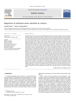
SENSORI Magnetici
magnetic SENSORS
SENSORI MAGNETICI SERIE SMC - SMP
MAGNETIC SENSORS SMC - SMP SERIES
PRINCIPIO DI FUNZIONAMENTO
WORKING PRINCIPLE
I sensori di prossimità magnetici sono costituiti da contatti reed le cui lamine di materiale magnetico, racchiuse in un bulbo di vetro contenente gas inerte, sono sensibili all’influenza di campi magnetici generati
da magneti permanenti, che producono sulle
lamine per il fenomeno di induzione magnetica, polarità
di segno opposto. Quando la forza di
attrazione supera la resistenza elastica delle lamine, queste si flettono l’una verso l’altra creando un contatto
elettrico. Le superfici di contatto delle lamine dei reed sono rivestite con
materiale pregiato,rendendoli adatti a pilotare, in funzione del rivestimento impiegato, circuiti a basse correnti o carichi induttivi elevati. I sensori magnetici rispetto ai tradizionali interruttori meccanici presentano i seguenti vantaggi:
- I contatti sono protetti dalla polvere, dall’ossidazione e dalla corrosione perchè sono
chiusi ermeticamente in bulbi contenenti gas inerti, l’azionamento dei contatti avviene
senza l’interposizione di meccanismi, sfruttando l’influenza di un campo magnetico.
- L’accuratezza dei rivestimenti galvanici delle superfici di contatto assicura una durata
di svariate decine di milioni di operazioni in condizioni elettriche di esercizio normali.
- Assoluta assenza di manutenzione e ingombri ridotti.
I sensori magnetici a contatto reed presentano diverse caratteristiche elettriche e
meccaniche oltre a differenti funzioni di uscita.
- Nella funzione normalmente aperta (N.O.) il contatto reed aperto nello stato di riposo, si chiude quando il magnete si avvicina. Sono provvisti di due fili.
- Nella funzione in scambio (S) entrambe le funzioni NO ed NC sono realizzate in
un unico bulbo di vetro, avvicinando e allontanando il magnete il contatto reed
commuta dalla condizione di riposo a quella di lavoro e viceversa. Sono provvisti
di tre fili, uno comune, uno N.O. ed uno N.C.
- Nella funzione bistabile un magnete interno pre-polarizza le lamine senza arrivare però a chiuderle. All’avvicinarsi del magnete con polarità concorde il campo magnetico viene rinforzato; in tal caso il contatto si chiude e rimane chiuso anche
quando il magnete di azionamento esce dalla zona di influenza. Per riaprire il contatto occorre che il magnete si avvicini con polarità discorde da quella del campo
di pre-polarizzazione.
Magnetic proximity switches are
made of reed contacts whose thin
plates, trapped in a glass bulb together with inerted gas, are easily
influenced by magnetic fields that
create magnetic induction, opposite polarization.
Magnetic attraction force makes
thin plates flex and touch each other
causing an electrical contact. the
plate’s surface has been treated
with a special material particularly
suitable for low current or high inductive circuits. magnetic sensors
compared to traditional mechanical
switches have the following advantage:
- Contacts are well protected against dust, oxidization and corrosion thanks to
the hermetic glass bulb and inerted gas; contacts are activated by means of a
magnetic field rather than mechanical parts.
- Special surface treatment of contacts assures in normal electrical conditions
many of working cycles.
- Maintenance free, reduce encumbrance.
The reed magnetic switches offer many electrical and mechanical characteristics
together with various output functions.
- When in normally open (N.O.) mode the open reed contact closes as magnet
approaches. They are supplied with two wires.
- When in the exchangeable (S) mode both N.O. an N.C. functions are made available by means of a single glass bulb. Placing the magnet close to or far from
the reed switch activates the two different positions. They are supplied with three
wires, one is in common, one is N.O. and one is N.C.
- In bistable function an internal magnet pre-polarizes the reed contact , but does
not close them. Placing a magnet with the same polarity close to it the magnetic field is intensified, causing the contact to close, and remains that way even
when the operating magnet moves away from the sensing area. The contact
opens again when a magnet with opposite polarity, compared to the magnetic
field, is placed close to it.
PROTEZIONI TIPICHE PER CONTATTI REED / TYPICAL REED CONTACT PROTECTIONS
La vita utile di un sensore magnetico dipende, per valori bassi di tensione o corrente, dalle caratteristiche meccaniche del contatto.
Per valori alti di tensione o corrente invece la durata è legata alle caratteristiche
del carico, in questi casi è opportuno installare sull'uscita del sensore una protezione esterna.
The lifespan of a magnetic sensor, at low values of tension and current, depends
on the mechanical characteristics of the contact.
Whilst at high tension and current values it’s the characteristics of the load that
influences the lifespan instead. In these cases it is suggestable to appliy some
form of external protection at the sensors output.
ESEMPIO DI FUNZIONAMENTO / EXAMPLE OF FUNCTIONING
A
B
AZIONATORE MAGNETE
MAGNET
ELEMENTO SENSORE (REED)
REED SENSOR
MAGNETE AZIONATORE
MAGNET
SENSORE
SENSOR
A= Avvicinamento laterale / B= Avvicinamento frontale
104
D:
Distanza max di funzionamento in funzione del tipo
di magnete adottato
D:
Max working distance in
relation to type of magnet
used
C:
Corsa differenziale riferita
all'allontanamento del
magnete dal sensore
C:
Differential stroke related to
magnet removal
D + C: Distanza di riapertura del
contatto in fase di
allontanamento
D + C: Distance during removal in
which contact opens
SENSORI MAGNETICI SERIE SMC - SMP
MAGNETIC SENSORS SMC - SMP SERIES
DISTANZE DI INTERVENTO SENSORE - MAGNETE
SENSORS AND MAGNETS SENSING DISTANCE
Nella tabella sono riportati due valori di distanza (D/C) in mm. Quello a sinistra
della barra si riferisce alla distanza di intervento, quello a destra definisce il valore di
isteresi al di sotto del quale il contatto si diseccita (vedi esempio di
funzionamento). I dati della tabella hanno valore approssimativo e sono riferiti
ad applicazioni su superfici non ferromagnetiche e con magnete in avvicinamento frontale, i sensori magnetici possono essere azionati anche con magnete
laterale. In caso di installazioni su superfici ferrose che disperdono il flusso magnetico, occorre interporre opportuni distanziatori di materiale amagnetico.
The above table states 2 distance values (D/C) in mm. D indicates the sensing
distance, C indicates the min. hysteresis value, under this value the contact switches off (see example of functioning). Data shown on the above table have an approximate value, referred to appliances which are not ferromagnetic and with magnet for frontal working. The magnetic sensors can also work with a lateral magnet. In case of setting-up on ferrous surfaces which scatter the magnetic flux,
it is necessary to interpose suitable spacers made of non-magnetic metal.
CONTATTO REED
REED CONTACT
M16
D/C
M20
D/C
M30
D/C
M300
D/C
M302
D/C
M304
D/C
SMC-06/08/10/12/09PG
NO
8/2
20/4
40/5
30/4
-
-
SMC-06/08/10/12/09PG
SCAMBIO / CHANGEOVER
6/3
17/3
33/5
23/5
-
-
SMC-12LM/18M/09PGM
NO
-
10/6
33/10
18/8
-
-
SMC-12LM/18M/09PGM
SCAMBIO / CHANGEOVER
-
10/6
33/10
18/8
-
-
SMC-12LBS/SMCP-12LBS
BISTABILE 60VA
6
20
40
-
-
-
SMC-12LMBS/SMCP-12LMBS
BISTABILE 120VA
6
20
40
-
-
-
SMP-302/304
NO
-
-
-
-
10/4
10/4
SMP-302/304
SCAMBIO / CHANGEOVER
-
-
-
-
10/4
10/4
SENSORE / SENSOR
SENSORI MAGNETICI BISTABILI / BISTABLE MAGNETIC SENSORS
Nel sensore bistabile il contatto si chiude solo in presenza della polarità NORD
del magnete (M) esterno di attivazione continuando a mantenere tale condizione anche quando lo stesso esce dalla zona di influenza.
Il contatto si riapre solo in presenza della polarità SUD del magnete (M) rimanendo in questa condizione anche quando il magnete esce dalla zona di influenza e potrà ritornare chiuso solo in presenza di magnete con polarità
NORD. I sensori bistabili sono forniti con contatto standard 60VA e con contatto potenziato a 120VA in versione metallica o plastica cilindrica M12.
In the bistable version, contact closes only when external activation magnet
(M) is in NORTH polarity position. This state is maintained even when Magnet
goes out of sensing area.
Contact opens back only when SOUTH polarity of magnet (M) is present,
maintaining this condition even when magnet goes out of sensing zone, and
can close again only when a NORTH polarity magnet is present.
Bistable sensors are supplied both in the metallic and plastic cylindrical M12
housing with 60VA standard contact and 120VA special powered contact.
APERTURA CONTATTO CON IL SUD
DEACTIVATED BY THE SOUTH POLARITY
CHIUSURA CONTATTO CON IL NORD
ACTIVATED BY THE NORTH POLARITY
SUD / SOUTH
NORD / NORTH
SCHEMI DI COLLEGAMENTO / WIRING DIAGRAMS
CONTATTO NORMALMENTE APERTO
NORMALY OPEN CONTACT
CONTATTO IN SCAMBIO
CHANGEOVER CONTACT
BLU / BLUE
MARRONE / BROWN
BLU / BLUE
F1
CONTATTO BISTABILE
BISTABLE CONTACT
NERO / BLACK
Vdc/ac
MARRONE / BROWN
Vdc/ac
BLU / BLUE
MARRONE / BROWN
F2
Vdc/ac
F3
ESECUZIONI A RICHIESTA / VERSION ON REQUEST
N.B.: A richiesta è possibile ordinare i sensori con cavi di lunghezza 5 e 10 m.
N.B.: Upon request cable for sensors with different lengths 5 and 10 metres is available.
105
SENSORI MAGNETICI SERIE SMC-SMP • MAGNETIC SENSORS SMC-SMP SERIES
• MODELLI CON CUSTODIA PLASTICA O METALLICA / MODELLI CILINDRICI E PARALLELEPIPEDI / GRADO DI PROTEZIONE IP67 / CAVO PVC LUNGHEZZA 2 MT
• MODELS WITH PLASTIC OR METALLIC HOUSING / CYLINDRICAL AND RECTANGULAR MODELS / IP RATING 67 / PVC CABLE 2 MT. LENGTH
CARATTERISTICHE TECNICHE
TECHNICAL CHARACTERISTICS
Dimensioni / Dimensions
mm
MODELLI CON CONTATTO N.O.
MODELS WITH N.O. CONTACT
MODELLI IN SCAMBIO
CHANGEOVER MODELS
Distanza di intervento sn*
Switching distance sn*
SMC06 NO
SMC08 NO
SMC10 NO
SMC000001
SMC000004
SMC000015
SMC06 S
SMC08 S
SMC10 S
SMC000002
SMC000006
SMC000016
mm
20
17
20
17
20
17
Tensione di commutazione max
Max switching voltage
V
220
150
220
150
220
150
Corrente di commutazione max
Max switching current
A
0,5
1
0,5
1
0,5
1
W/VA
50
20
50
20
50
20
Frequenza di lavoro max
Max switching frequency
Hz
230
250
230
250
230
250
Tempo di attuazione contatto
Contact actuation time
ms
Potenza di commutazione max
Max switching power
Ripetibilità
Repeatability
Limiti di temperatura
Temperature limits
2
2
mm
2
± 0.3
- 25 ÷ + 100
°C
Diagramma di commutazione pag. 108
Switching power diagram page 108
D1
D2
D1
D2
D1
D2
Schema di collegamento pag. 105
Wiring diagram page 105
F1
F2
F1
F2
F1
F2
Custodia
Housing
Ottone nichelato
Nickelled brass
Ottone nichelato
Nickelled brass
CARATTERISTICHE TECNICHE
TECHNICAL CHARACTERISTICS
Dimensioni / Dimensions
mm
MODELLI CON CONTATTO N.O.
MODELS WITH N.O. CONTACT
MODELLI IN SCAMBIO
CHANGEOVER MODELS
Distanza di intervento sn*
Switching distance sn*
SMC18M NO
SMC09PG NO
SMC000032
SMC000037
mm
SMC09PGM NO
SMC000010
SMC18M S
SMC09PG S
SMC09PGM S
SMC000034
SMC000014
SMC000012
10
20
17
10
Tensione di commutazione max
Max switching voltage
V
250
500
220
150
250
500
Corrente di commutazione max
Max switching current
A
3
1
0,5
1
3
1
W/VA
120
60
50
20
120
60
Frequenza di lavoro max
Max switching frequency
Hz
100
150
230
250
100
150
Tempo di attuazione contatto
Contact actuation time
ms
4
4,5
4
4,5
Potenza di commutazione max
Max switching power
Ripetibilità
Repeatability
Limiti di temperatura
Temperature limits
2
± 0.3
mm
- 25 ÷ + 100
°C
Diagramma di commutazione pag. 108
Switching power diagram page 108
D3
D4
D1
D2
D3
D4
Schema di collegamento pag. 105
Wiring diagram page 105
F1
F2
F1
F2
F1
F2
Custodia
Housing
Ottone nichelato
Nickelled brass
* La distanza di intervento sn è riferita al magnete M20, per utilizzo di altri magneti AECO vedere tabella pag. 105.
* Sensing distance is referred to our M20 magnet in frontal approach. For all other aeco magnets, PLS refer to table on page 105.
106
Ottone nichelato
Nickelled brass
SENSORI MAGNETICI SERIE SMC-SMP • MAGNETIC SENSORS SMC-SMP SERIES
• MODELLI CON CUSTODIA PLASTICA O METALLICA / MODELLI CILINDRICI E PARALLELEPIPEDI / GRADO DI PROTEZIONE IP67 / CAVO PVC LUNGHEZZA 2 MT
• MODELS WITH PLASTIC OR METALLIC HOUSING / CYLINDRICAL AND RECTANGULAR MODELS / IP RATING 67 / PVC CABLE 2 MT. LENGTH
SMC12 NO
SMC/P12L NO
SMC/P12LM NO
SMC000019
SMC000225
SMC000231
S
6
SMC12LM NO
SMC000028
SMC12 S
SMC/P12L S
SMC/P12LM S
SMC12LM S
SMC000020
SMC000228
SMC000234
SMC000029
20
17
20
17
220
150
220
150
250
500
250
500
0,5
1
0,5
1
3
1
3
1
50
20
50
20
120
60
120
60
230
250
230
250
100
150
100
150
4
4,5
4
4,5
2
10
2
10
± 0.3
- 25 ÷ + 100
D1
D2
D1
D2
D3
D4
D3
D4
F1
F2
F1
F2
F1
F2
F1
F2
Ottone nichelato
Nickelled brass
SMP302 NO
SMP304 NO
SMP000001
SMP000005
S
2
Ottone nichelato
Nickelled brass
Plastica
Plastic
MODELLI BISTABILI / BISTABLE MODELS
SMP302 S
SMP304 S
SMC12L BS
SMC12LM BS
SMC/P12L BS
SMC/P12LM BS
SMP000004
SMP000010
SMC000237
SMC000240
SMC000243
SMC000246
20
17
20
17
15
20
15
20
220
150
220
150
230
250
230
250
0,5
1
0,5
1
3
3
3
3
50
20
50
20
60
120
60
120
230
250
230
250
230
100
230
100
2,5
3,5
2,5
3,5
± 0.3
± 0.5
± 0.3
± 0.5
D5
D6
2
2
± 0.3
- 25 ÷ + 100
- 25 ÷ + 80
D1
D2
D1
D2
F1
F2
F1
F2
Plastica
Plastic
Alluminio anodizzato
Anodized aluminium
D5
D6
F3
Ottone nichelato
Nickelled brass
Plastica
Plastic
107
DIAGRAMMI DI COMMUTAZIONE • SWITCHING POWER DIAGRAMS
D1
V
200
V
150
100
100
50
50
I
0
0,2
0,4
0,6
0,8
D5
400
300
200
100
1
1,5
2
2,5
200
100
I
0,2
0,4
0,6
0,8
0
0,5
V
V
250
250
D6
225
1
1,5
2
2,5
3
225
200
200
175
175
150
150
125
125
100
100
75
75
50
50
0
3
I
0
1
25
I
0
0,5
300
0
1
V
500
400
0
V
500
0
D3
200
150
0
D4
D2
25
0
0,6
1,2
1,8
2,4
3
A
0
0
0,6
1,2
1,8
2,4
3
A
MAGNETI - MAGNETS
MODELLO
MODEL
M-16
M-20
M-30
ACM000004
ACM000006
ACM000007
Plastoferrite
Plastoferrite
MODELLO
MODEL
Ferrite
Ferrite
Ferrite
Ferrite
M-300
M-302
M-304
ACM000010
ACM000002
ACM000003
Ferrite
Ferrite
Ferrite
Ferrite
Ferrite
Ferrite
N.B. A RICHIESTA SONO DISPONIBILI MAGNETI DI DIVERSE DIMENSIONI. - N.B. UP ON REQUEST MAGNETS OF DIFFERENT SIZES.
SENSORI MAGNETICI SPECIALI A RICHIESTA
SPECIAL MAGNETIC SENSORS UPON REQUEST
GENERALITÀ
FEATURES
Nella famiglia dei sensori magnetici la Società AECO propone, oltre ai modelli
standard, una molteplice offerta di modelli su richiesta del cliente.
Le varianti possibili sono numerose, possono riguardare la parte meccanica con
diverse forme sia metalliche che plastiche, la parte elettrica con ampia scelta di
ampolle reed con diverse potenze di commutazione, per temperature elevate oppure in esecuzioni particolari con più contatti presenti nello stesso sensore, versioni con funzionamento bistabile, di sicurezza, omologate ATEX, le varianti sono riferite anche ai collegamenti elettrici che possono essere forniti con cavi particolari, connettori di vario tipo, ecc.
Within the existing magnetic sensor range, Aeco Srl also proposes, besides the
standard models, a variety of models available upon customer’s request.
There are several modifications one can make to the standard type and these can
involve both the mechanical and plastic parts, also the electrical features with the
possibility of choosing among different reed bulbs with various switching functions, for high temperature applications or special models with several output contacts present within the same sensor; versions with bistable function or ATEX versions for safety applications. Above modifications also refer to the electrical wiring
which can be supplied with special cables or different types of connectors.
108
Aeco s.r.l.
via G. Leopardi, 5 - 20065 Inzago (Milano) ITALY
Tel. ++39 02 954381 - Fax ++39 02 9548528
email: [email protected]
www.aecosensors.com
© Copyright 2026 Paperzz