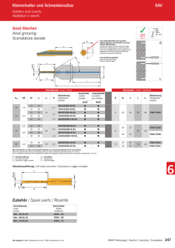
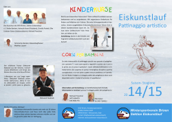
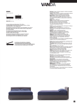
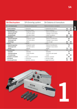
SIN Bohrstangen NC-Innenbearbeitung SIN Boring bars SIN Bareni Internal machining Lavorazione interna Innenstechdrehen Internal groove turning Scanalatura e copiatura interna Seite Page Pagina 152 – 164 mit IK with ic con ic L Dx AKL f Dmin d R L Rechte Ausführung abgebildet Right-hand execution shown Versione destra in figura ET 2 EB Grundhalter / Basic holder / Corpo utensile Bezeichnung Designation Articolo Dmin EB ET AKL d L f Dx Schneideinsatz Insert Inserto SIN20M-045-20-16 R/L 16 2 4,5 20 16 110 13,0 27,5 212... SIN20M-045-30-16 R/L 16 2 4,5 30 16 110 13,0 27,5 212... SIN30M-055-27-20 R/L 20 3 5,5 27 20 135 16,5 33,0 316... SIN30M-055-40-20 R/L 20 3 5,5 40 20 135 16,5 33,0 316... SIN30-080-30-20 R/L 28 3 8,0 30 20 135 18,5 31,0 320... SIN30-080-50-20 R/L 28 3 8,0 50 20 135 18,5 31,0 320... SIN30-080-30-25 R/L 28 3 8,0 30 25 150 21,0 41,0 320... SIN30-080-50-25 R/L 28 3 8,0 50 25 150 21,0 41,0 320... SIN30-110-30-25 R/L 32 3 11,0 30 25 150 24,0 43,0 320... SIN30-110-50-25 R/L 32 3 11,0 50 25 150 24,0 43,0 320... Grundhalter und Zubehör / Basic holder and accessories / Corpo utensile e accessori Grundhalter Basic holder Corpo utensile 138 Schraube Screw Vite Verschlussring Locking Ring Anello di tenuta SIN20M....-16 R/L AS 0018 KVR16 SIN30M....-20 R/L AS 0019 KVR20 SIN30-....-20 R/L SS 1111 KVR20 SIN30-....-25 R/L SS 1111 KVR25 ARNO®-Werkzeuge | Stechen | Grooving | Scanalatura Alle Angaben in mm / Dimensions in mm / Tutte le dimensioni in mm Geometrie NC Geometry Geometria Standardausführung Standard geometry Esecuzione standard ɏQS¤[JTJPOTHFTDIMJGGFOFS Schneideinsatz ɏ[XFJTFJUJH ɏTQF[JFMMF(FPNFUSJF[VS Spaneinschnürung ɏ[VN&JOTUFDIFOCFJLMFJOFOCJT mittleren Spanquerschnitten ɏHFSJOHF4DIOJUULS¤GUFEVSDI scharfe Schneidkante ɏG¼SFJOF7JFM[BIMWPO Werkstückstoffen ɏG¼S*OOFOVOE"VFO bearbeitung ɏQSFDJTJPOHSPVOEJOTFSU ɏUXPDVUUJOHFEHFT ɏTQFDJBMHFPNFUSZXJUIDIJQ contraction ɏGPSHSPPWJOHXJUITNBMMUP medium chip-cross-section ɏMPXDVUUJOHGPSDFTCFDBVTFPG sharp cutting edges ɏGPSBOVNCFSPGXPSLQJFDF materials ɏGPSJOUFSOBMBOEFYUFSOBM machining ɏJOTFSUPSFUUJGJDBUPEJQSFDJTJPOF ɏUBHMJFOUJ ɏHFPNFUSJBTQFDJBMFBEBUUBBMMB contrazione del truciolo ɏQFSVOBTDBOBMBUVSBEJTF[JPOJ di truciolo piccole e medie ɏUBHMJPEPMDFQFSJMUBHMJFOUF affilato ɏBEBUUPBEVOWBTUPOVNFSP di materiali ɏVTPJOUFSOPFEFTUFSOP Kopierausführung -12 Geometry for copying -12 Geometria di copiatura -12 ɏQS¤[JTJPOTHFTDIMJGGFOFS Schneideinsatz ɏ[XFJTFJUJH ɏTQF[JFMMF(FPNFUSJF[VS Spaneinschnürung ɏNJUpQPTJUJWFN4QBOXJOLFM an allen drei Hauptschneiden ɏ"OXFOEVOHFOUTQSJDIUEFS Standardausführung, jedoch zusätzlich zum Kopierdrehen bei mittleren Spanquerschnitten ɏG¼S*OOFOVOE"VFO bearbeitung ɏQSFDJTJPOHSPVOEJOTFSU ɏUXPDVUUJOHFEHFT ɏTQFDJBMHFPNFUSZGPSDIJQ contraction ɏpQPTJUJWFSBLFBOHMFPOBMM three cutting edges ɏTBNFBQQMJDBUJPOBTTUBOEBSE execution, but also for copyturning with medium chipcross-section ɏGPSJOUFSOBMBOEFYUFSOBM machining ɏJOTFSUPSFUUJGJDBUPEJQSFDJTJPOF ɏUBHMJFOUJ ɏHFPNFUSJBTQFDJBMFBEBUUBBMMB contrazione del truciolo ɏBOHPMPEJUBHMJPBpQPTJUJWP tri-direzionale ɏNFEFTJNBBQQMJDB[JPOF dell’esecuzione standard, ma adatto alla tornitura di sezioni di truciolo piccole e medie ɏVTPJOUFSOPFEFTUFSOP AM-Geometrie AM geometry Geometria AM ɏQS¤[JTJPOTHFTJOUFSUFSTFJUJHFS Schneideinsatz ɏ4DIOFJEFJOTBU[[VN4UFDI drehen, Ein- und Abstechen ɏIPIF;FSTQBOVOHTMFJTUVOH durch stabile Schneidkante ɏHFSJOHF4DIOJUULS¤GUFEVSDI positive Schneidengeometrie ɏG¼S*OOFOVOE"VFO bearbeitung ɏQSFDJTJPOTJOUFSFEUXJOFEHF inserts ɏJOTFSUTGPSHSPPWFUVSOJOH cut in and withdraw ɏDPOTJEFSBCMFDIJQSFNPWBM via stable cutting edge ɏNJOJNVNDVUUJOHGPSDFWJB positive cutting geometry ɏGPSJOUFSOBMBOEFYUFSOBM machining ɏJOTFSUPTJOUFSJ[[BUPBUBHMJ ɏJOTFSUPQFSUPSOJUVSBEJ scanalatura ɏDPOTJEFSFWPMFWPMVNFEJUSVDJPMP grazie alla stabilità del tagliente ɏUBHMJPEPMDFQFSMBHFPNFUSJBEJ taglio positiva ɏVTPJOUFSOPFEFTUFSOP Vollradiusausführung V Full radius execution V Esecuzione a raggio completo V ɏQS¤[JTJPOTHFTDIMJGGFOFS Schneideinsatz ɏ[XFJTFJUJH ɏ7PMMSBEJVT ɏG¼S&JOTUJDIFVOE/BDILPQJFS operationen bei kleinen Spanquerschnitten ɏ;FSTQBOVOHLVS[TQBOFOEFS Werkstoffe ɏG¼S*OOFOVOE"VFO bearbeitung ɏQSFDJTJPOHSPVOEJOTFSU ɏUXPDVUUJOHFEHFT ɏGVMMSBEJVT ɏGPSHSPPWJOHBOEDPQZUVSOJOH operations with small chipcross-section ɏNBDIJOJOHPGTIPSUDIJQQJOH materials ɏGPSJOUFSOBMBOEFYUFSOBM machining ɏJOTFSUPSFUUJGJDBUPEJQSFDJTJPOF ɏUBHMJFOUJ ɏSBHHJPDPNQMFUP ɏQFSTDBOBMBUVSBFDPQJBUVSB di ridotte sezioni di taglio ɏMBWPSB[JPOFEJNBUFSJBMJB truciolo corto ɏVTPJOUFSOPFEFTUFSOP Alle Angaben in mm / Dimensions in mm / Tutte le dimensioni in mm ARNO®-Werkzeuge | Stechen | Grooving | Scanalatura 2 139 Geometrie NC Geometry Geometria 2 140 Vollradiusausführung VK Full radius execution VK Esecuzione a raggio completo VK ɏQS¤[JTJPOTHFTDIMJGGFOFS Schneideinsatz ɏ[XFJTFJUJH7PMMSBEJVT ɏG¼S&JOTUJDIFVOE/BDILPQJFS operationen bei entsprechenden Konturen bis mittlere Spanquerschnitte ɏQSFDJTJPOHSPVOEJOTFSU ɏUXPDVUUJOHFEHFTGVMMSBEJVT ɏGPSHSPPWJOHBOEDPQZUVSOJOH operations up to medium chipcross-section ɏJOTFSUPSFUUJGJDBUPEJQSFDJTJPOF ɏUBHMJFOUJSBHHJPDPNQMFUP ɏQFSTDBOBMBUVSBFDPQJBUVSBEJ sezioni di truciolo medie Particolarità: ɏHFPNFUSJBBEBUUBBMDPOUSPMMPEFM truciolo di materiali a truciolo lungo ɏVTPJOUFSOPFEFTUFSOP Besonderheit: ɏTQF[JFMMF4QBOGPSNHFPNFUSJFG¼S kontrollierten Spanbruch auch bei langspanenden Werkstoffen ɏG¼S*OOFOVOE"VFOCFBSCFJUVOH Particularity: ɏTQFDJBMDIJQCSFBLFSGPS controlled-chipbreaking when machining long chipping materials ɏGPSJOUFSOBMBOEFYUFSOBM machining Aluminiumausführung -ALU Aluminium type -ALU Geometria -ALU ɏQS¤[JTJPOTHFTDIMJGGFOFS Schneideinsatz ɏ[XFJTFJUJH ɏTQF[JFMMF(FPNFUSJF[VS Spaneinschnürung ɏNJUpQPTJUJWFN4QBOXJOLFM an allen drei Hauptschneiden ɏG¼S&JOTUJDIVOE,PQJFS arbeiten bei NE-Metallen und Kunststoff ɏG¼S*OOFOVOE"VFO bearbeitung ɏQSFDJTJPOHSPVOEJOTFSU ɏUXPDVUUJOHFEHFT ɏTQFDJBMHFPNFUSZGPSDIJQ contraction ɏpQPTJUJWFSBLFBOHMFPOBMM three cutting edges ɏHSPPWJOHBOEDPQZUVSOJOH of non-ferrous materials and plastics ɏGPSJOUFSOBMBOEFYUFSOBM machining ɏJOTFSUPSFUUJGJDBUPEJQSFDJTJPOF ɏUBHMJFOUJ ɏHFPNFUSJBBEBUUBTQFDJGJDBNFOUF alla contrazione del truciolo ɏBOHPMPEJUBHMJPBpQPTJUJWP tri-direzionale ɏQFSTDBOBMBUVSBFDPQJBUVSB dimateriali non ferrosi e plastici ɏVTPJOUFSOPFEFTUFSOP Ausführung für Sicherungsringeinstiche Circlip grooves execution Esecusionei per canali ɏQS¤[JTJPOTHFTDIMJGGFOFS Schneideinsatz ɏ[XFJTFJUJH ɏG¼SBMMF&JOTUJDIFOBDI DIN 471/472 unter Verwendung von nur einer Unterstützplatte ɏG¼S*OOFOVOE"VFO bearbeitung ɏQSFDJTJPOHSPVOEJOTFSU ɏUXPDVUUJOHFEHFT ɏGPSBMMHSPPWFTUP%*/ by using only one support blade for all widths ɏGPSJOUFSOBMBOEFYUFSOBM machining ɏJOTFSUPSFUUJGJDBUPEJQSFDJTJPOF ɏUBHMJFOUJ ɏQFSHPMFTFDPOEPOPSNB%*/ 471/472 usando una sola lama per tutti gli spessori ɏVTPJOUFSOPFEFTUFSOP ARNO®-Werkzeuge | Stechen | Grooving | Scanalatura Alle Angaben in mm / Dimensions in mm / Tutte le dimensioni in mm Sortenbeschreibung NC Grade description Descrizione delle Qualitá Beschichtet / Coated / Rivestito AM27C CVD-Mehrlagenbeschichtung Bearbeitung von Stahl, Stahlguss mit mittleren bis hohen Schnittgeschwindigkeiten, mittleren bis großen Spanquerschnitten und wechselnden Schnitttiefen. Speziell einsetzbar für Stähle mit starker Verklebeneigung. Einsatz im Schlicht- und mittleren Schruppbereich. CVD-multilayer coating Machining steel, cast steel as well as grey cast iron, at medium to high cutting speeds, medium to large chip-cross-sections and varying depths of cut. Used for finishing and medium roughing. Rivestimento multistrato CVD Lavorazione di acciaio, acciaio da fusione con velocità di taglio da medie ad elevate, sezioni di truciolo medie e larghe e profondità di taglio varie. Per finitura e media sgrossatura. CVD-multilayer coating Machining steel, stainless steel and cast steel, at medium to large chip-cross-sections and medium to low cutting speeds under unfavourable machining conditions where good toughness is required. Rivestimento multistrato CVD Lavorazione di acciaio inossidabile e acciaio da fusione per sezioni di taglio medie e grandi e velocità di taglio medie e basse In condizioni di lavorazione non favorevoli quando è richiesta una buona tenacità. AM35C CVD-Mehrlagenbeschichtung Bearbeitung von Stahl, rostfreiem Stahl sowie Stahlguss bei mittleren bis großen Spanquerschnitten und mittleren bis geringen Schnittgeschwindigkeiten unter ungünstigen Bearbeitungsbedingungen und hohen Zähigkeitsanforderungen. AM350 CVD-Mehrlagenbeschichtung Zur Bearbeitung von Stahl und Stahlguss mit hohen Schnittgeschwindigkeiten, mittleren bis hohen Spanquerschnitten und wechselnden Schnitttiefen. Verschleißfeste Sorte durch speziell aufeinander abgestimmtes Substrat und Beschichtung. Einsatz im Schlicht- und mittleren Schruppbereich. CVD-multilayer coating Grade with a good combination of wear resistance and toughness for turning steel, stainless steel as well as cast steel at medium chip-crosssections and medium to high cutting speeds. Can also be used under unfavourable machining conditions. Special grade for stainless steel (austenitic). Apply in finishing and medium roughing applications. Rivestimento multistrato CVD Grado resistente all’usura, buona tenacità per la tornitura dell’acciaio, acciaio inossidabile, sezioni di taglio medie, velocità di taglio medie ed elevate, in condizioni di lavoro non favorevoli. Grado particolarmente adatto a acciai austenitici ed acciai inossidabili. PVD-multilayer coating An improved PVD coating on a tough and wear resistant carbide grade. Due to the higher cobalt content this grade contains all the required toughness for part-off and grooving applications. AM5035 is excellent at machining most steel, stainless steel and hard to machine materials. Rivestimento multiplo PVD Un rivestimento PVD di ultima generazione, su base di metallo duro resistente all’usura e con una buona tenacità. Grazie all’elevato contenuto di cobalto, questa qualità ha la tenacità necessaria per la lavorazione di gole e per la troncatura. La qualità AM5035 è indicata per la lavorazione della maggior parte degli acciai, dell’acciaio inossidabile, della ghisa e di materiali difficili da lavorare. CVD-multilayer coating For machining grey cast iron, cast iron with graphite and hard cast material. Also suitable for stainless steel, steel and cast steel at medium to high cutting speed. Apply in finishing and lighter roughing applications. Rivestimento multistrato CVD Lavorazione della ghisa, ghisa sferoidale, ghisa temperata, acciaio, fusioni d’acciaio a velocità di taglio medie, elevate e molto elevate; per finitura e tagli medi. CVD-multilayer coating Machining of steel, stainless steel, spheroidal cast iron, cast steel and grey cast iron at high cutting speeds under stable machining conditions. Rivestimento multistrato CVD Lavorazione dell’acciaio, acciaio inossidabile, ghisa sferoidale, fusioni d’acciaio a velocità di taglio elevate in codizioni di taglio stabili. 2 AM5035 PVD-Mehrlagenbeschichtung Eine verbesserte PVD-Beschichtung auf einem zähen und verschleißfesten Hartmetallsubstrat. Mit einem höheren Kobaltgehalt verfügt diese Sorte über die nötige Zähigkeit, um den Ansprüchen beim Ein- und Abstechen gerecht zu werden. AM5035 ist ausgezeichnet für die Bearbeitung der meisten Stähle, nichtrostenden Stählen und schwer zerspanbaren Stählen. AR17C CVD-Mehrlagenbeschichtung Bearbeitung von Grauguss, Gusseisen mit Kugelgraphit und Hartguss. Auch geeignet für rostfreien Stahl, Stahl und Stahlguss bei mittleren bis höchsten Schnittgeschwindigkeiten. Einsatz im Schlicht- und unteren Schruppbereich. AR27C CVD-Mehrlagenbeschichtung Bearbeitung von Stahl, Stahlguss, rostfreiem Stahl, Gusseisen mit Kugelgraphit sowie Grauguss mit hohen Schnittgeschwindigkeiten unter stabilen Bearbeitungsbedingungen. Alle Angaben in mm / Dimensions in mm / Tutte le dimensioni in mm ARNO®-Werkzeuge | Stechen | Grooving | Scanalatura 141 Sortenbeschreibung NC Grade description Descrizione delle Qualitá Beschichtet / Coated / Rivestito AT10 PVD-Mehrlagenbeschichtung Zur Bearbeitung von Aluminium und Aluminiumlegierungen, Kupfer, Bronze, NE-Metallen und hochschmelzenden Werkstoffen bei mittleren Spanquerschnitten und unter ungünstigen Bearbeitungsbedingungen. Auch geeignet für rostfreie Stähle. Rivestimento multistrato PVD Per lavorare l’alluminio e sue leghe, il rame, il bronzo, materiali non ferrosi, e metalli refrattari (per esempio Niobio, Tantalio, Molibdeno, Wolframio) per sezioni di taglio medie e in condizioni di taglio non favorevoli. PVD-multilayer coating Grade for machining aluminium and aluminiumalloy, cooper, brass, non-ferrous materials and refractory metals at medium cutting and under unfavourable cutting conditions. Also suitable for stainless steel. Unbeschichtet / Uncoated / Non rivestito AK10 2 Feinkorn-Hartmetall zur Bearbeitung von Gusswerkstoffen, Leicht- und Buntmetallen, hochschmelzenden Metallen und gehärteten Stählen bis 55 HRC. In Verbindung mit der Spanleitstufengeometrie-ALU besonders für das Stechdrehen von Al und Cu-Legierungen zu empfehlen. Submicron carbide grade for machining cast materials, light and non-ferrous materials, refractory metals, hardened steels up to 55 HRC. In connection with chipbreaker-ALU specially suitable for machining Al- and Cu-alloys. Metallo duro submicrograna per la lavorazione di fusioni, leghe leggere e non ferrose, metalli refrattari, metalli temprati fino a 55 HRC. Abbinato al rompitruciolo-ALU è specificamente adatto per la lavorazione leghe di alluminio e rame. Machining of steel, steels with medium tensile strength as well as stainless steel and spheroidal cast iron. Limited use on grey cast iron. Lavorazione dell’acciaio, acciai di dureza media come l’acciaio inossidabile e la ghisa sferoidale. Uso limitato sulla ghisa grigia. Machining of hardened materials (hardened steels). For example, hard cast iron, hardened steel from 50 HRC onwards, Nihard and stellite. Lavorazione di materiali duri (acciai temprati). P.e. : ghisa temprata, acciaio temprato > 50 HRC, Nihard e stellite. Machining of non-ferrous metals, aluminium alloys with silicon, glass- and coal-fiber reinforced materials, spheroidal cast iron, at high cutting speeds. Sharp cutting edges enable low cutting forces and extremely good surface finish. Finishing and super finishing even at interrupted cuts. Lavorazione dei metalli non ferrosi, leghe d’alluminio con basso tenore di Silicio, materiali rinforzati al vetro e fibre di carbonio, a velocità di taglio elevate. Il tagliente affilato rende possibile bassi sforzi di taglio ed una finitura superficiale estremamente buona. Finitura e super finitura anche con taglio interrotto. CERMET Bearbeitung von Stahl, Stählen mittlerer Festigkeit sowie rostfreiem Stahl und Gusseisen mit Kugelgraphit. Bedingt einsetzbar für Grauguss. AH7520 (CBN) Bearbeitung von gehärteten Werkstoffen (sekundärharte Eisenwerkstoffe). Z. B.: Hartguss, gehärtete Stähle ab 50 HRC, Nihard und Stellite. AN8020 (PKD) Bearbeitung von NE-Metallen, Aluminiumlegierungen mit Siliziumanteilen, glas- und kohlefaserverstärkte Kunststoffe, Kugelgraphitguss bei hohen Schnittdaten. Durch die scharfe Schneidkante entstehen geringe Schnittdrücke und sehr gute Oberflächengüten bei extrem hoher Wärmeleitfähigkeit. Feinund Feinstbearbeitung bei glattem und unterbrochenem Schnitt. 142 ARNO®-Werkzeuge | Stechen | Grooving | Scanalatura Alle Angaben in mm / Dimensions in mm / Tutte le dimensioni in mm Schneideinsätze NC Inserts Inserti EB NC-Standard Standardausführung / Standard geometry / Esecuzione standard Sorten / Grades / Gradi 12,0 7/15° 0,1 2,0 12,0 7/15° 0,1 0° 21201TN 2,0 12,0 7/15° 0,1 0° 21204 2,0 12,0 7/15° 0,4 12° 31602 3,0 16,0 7/15° 0,2 12° 31602FN 3,0 16,0 7/15° 0,2 0° 31602TN 3,0 16,0 7/15° 0,2 0° 31604 3,0 16,0 7/15° 0,4 12° 32002 3,0 20,0 6/16° 0,2 12° 32002FN 3,0 20,0 6/16° 0,2 0° 32002TN 3,0 20,0 6/16° 0,2 0° 32004 3,0 20,0 6/16° 0,4 12° 42202 4,0 22,0 6/9,5° 0,2 12° 42202FN 4,0 22,0 6/9,5° 0,2 0° 42202TN 4,0 22,0 6/9,5° 0,2 0° 42204 4,0 22,0 6/9,5° 0,4 12° 42210 4,0 22,0 6/9,5° 1,0 12° 52502 5,0 25,0 6/8,5° 0,2 12° 52502FN 5,0 25,0 6/8,5° 0,2 0° 52502TN 5,0 25,0 6/8,5° 0,2 0° 52504 5,0 25,0 6/8,5° 0,4 12° 63002 6,0 30,0 6° 0,2 12° 63002FN 6,0 30,0 6° 0,2 0° 63002TN 6,0 30,0 6° 0,2 0° 63004 6,0 30,0 6° 0,4 12° 63010 6,0 30,0 6° 1,0 12° 83804 8,0 38,0 6° 0,4 12° 83804FN 8,0 38,0 6° 0,4 0° 83804TN 8,0 38,0 6° 0,4 0° 104604 10,0 46,0 6° 0,4 12° 104604FN 10,0 46,0 6° 0,4 0° 104604TN 10,0 46,0 6° 0,4 0° Hinweis für AN8020 und AH7520: Einseitig bestückte Schneideinsätze mit einem Spanwinkel von 0° Remark for AN8020 and AH7520 inserts: single-sided with a rank angle of 0° Nota gli inserti AN8020 e AH7520 hanno un solo tagliente con un angolo di taglio di 0° ! = Spanwinkel Rake angle Angolo di taglio AN8020 ! AH7520 ! CERMET ! AT10 ! hochhart ultra-hard extra duri 2 Außen und Innen External and internal Esterno ed interno Nur Außen External only Solo esterno Hauptanwendung Main application Applicazione principale Nebenanwendung Secondary application Applicazione secondaria P M ! ! ! K N S H Alle Angaben in mm / Dimensions in mm / Tutte le dimensioni in mm AR27C 2,0 21201FN AR17C 12° 21201 Anwendung Application Applicazione AM5035 ! AM350 R AM35C EB ± 0,02 L ± 0,02 AM27C Bezeichnung Designation Articolo AK10 unbeschichtet uncoated non rivestito beschichtet / coated / rivestito ! ! ! ! ! ! ARNO®-Werkzeuge | Stechen | Grooving | Scanalatura 143 Schneideinsätze NC Inserts Inserti EB NC-12 Kopierausführung / Geometry for copying / Geometria di copiatura geschliffen ground rettificato Sorten / Grades / Gradi 21201-12 2,0 12,0 7/15° 0,1 12° 21202-12 1,9 11,9 7/15° 0,2 12° 31602-12 3,0 16,0 7/15° 0,2 12° 31604-12 2,9 15,6 7/15° 0,4 12° 32002-12 3,0 20,0 6/16° 0,2 12° 32004-12 2,9 19,7 6/16° 0,4 12° 42202-12 4,0 22,0 6/9,5° 0,2 12° 42204-12 3,9 21,7 6/9,5° 0,4 12° 52502-12 5,0 25,0 6/8,5° 0,2 12° 52504-12 4,9 24,6 6/8,5° 0,4 12° 63002-12 6,0 30,0 6° 0,2 12° 83804-12 8,0 38,0 6° 0,4 12° 104604-12 10,0 46,0 6° 0,4 12° ! = Spanwinkel Rake angle Angolo di taglio AN8020 hochhart ultra-hard extra duri AH7520 CERMET AK10 ! AT10 ! AR27C Anwendung Application Applicazione AR17C ! AM5035 R AM350 EB ± 0,02 L ± 0,02 AM35C Bezeichnung Designation Articolo AM27C 2 unbeschichtet uncoated non rivestito beschichtet / coated / rivestito Außen und Innen External and internal Esterno ed interno Nur Außen External only Solo esterno Hauptanwendung Main application Applicazione principale Nebenanwendung Secondary application Applicazione secondaria P M ! ! K ! N S ! ! ! H 144 ARNO®-Werkzeuge | Stechen | Grooving | Scanalatura Alle Angaben in mm / Dimensions in mm / Tutte le dimensioni in mm Schneideinsätze NC Inserts Inserti EB NC-AM Kopierausführung / Geometry for copying / Geometria di copiatura gesintert sintered sinterizzato Sorten / Grades / Gradi 21202-AM 2,06 12,0 6/15° 0,2 6°/20° 31602-AM 3,06 16,0 6/15° 0,2 6°/20° 32002-AM 3,06 20,0 6/15° 0,2 6°/20° 42204-AM 4,06 22,0 6/9,5° 0,4 6°/20° 52504-AM 5,06 25,0 6/8,5° 0,4 6°/20° 63008-AM 6,06 30,0 6° 0,8 6°/20° 83808-AM 8,06 38,0 6° 0,8 6°/20° 104608-AM 10,07 46,0 6° 0,8 6°/20° ! = Spanwinkel Rake angle Angolo di taglio AN8020 hochhart ultra-hard extra duri AH7520 CERMET AT10 AR27C Anwendung Application Applicazione AR17C ! AM5035 R AM350 L AM35C EB ± 0,05 AM27C Bezeichnung Designation Articolo AK10 unbeschichtet uncoated non rivestito beschichtet / coated / rivestito 2 Außen und Innen External and internal Esterno ed interno Nur Außen External only Solo esterno Hauptanwendung Main application Applicazione principale Nebenanwendung Secondary application Applicazione secondaria P M ! ! K N S ! ! H Alle Angaben in mm / Dimensions in mm / Tutte le dimensioni in mm ARNO®-Werkzeuge | Stechen | Grooving | Scanalatura 145 Schneideinsätze NC Inserts Inserti EB NC-V Vollradiusausführung / Full radius execution / Esecuzione a raggio completo Sorten / Grades / Gradi 2,0 12,0 7/15° 1,0 2,0 12,0 7/15° 1,0 0° 21210V-TN 2,0 12,0 7/15° 1,0 0° 31615V 3,0 16,0 7/15° 1,5 12° 31615V-FN 3,0 16,0 7/15° 1,5 0° 31615V-TN 3,0 16,0 7/15° 1,5 0° 32015V 3,0 20,0 6/16° 1,5 10° 32015V-FN 3,0 20,0 6/16° 1,5 0° 32015V-TN 3,0 20,0 6/16° 1,5 0° 10° 42220V 4,0 22,0 6/9,5° 2,0 42220V-FN 4,0 22,0 6/9,5° 2,0 0° 42220V-TN 4,0 22,0 6/9,5° 2,0 0° 10° 52525V 5,0 25,0 6/8,5° 2,5 52525V-FN 5,0 25,0 6/8,5° 2,5 0° 52525V-TN 5,0 25,0 6/8,5° 2,5 0° 10° 63030V 6,0 30,0 6° 3,0 63030V-FN 6,0 30,0 6° 3,0 0° 63030V-TN 6,0 30,0 6° 3,0 0° 83840V 8,0 38,0 6° 4,0 10° 83840V-FN 8,0 38,0 6° 4,0 0° 83840V-TN 8,0 38,0 6° 4,0 0° 10° 104650V 10,0 46,0 6° 5,0 104650V-FN 10,0 46,0 6° 5,0 0° 104650V-TN 10,0 46,0 6° 5,0 0° Achtung: Beim Einsatz von Schneideinsätzen in Vollradiusausführung muss die Unterstützplatte abgeändert werden. Attention: The use of full radius inserts require a slightly modified support blade. Attenzione: l’utilizzo degli inserti a raggio completo rende necessaria una modifica della lama. Hinweis für AN8020 und AH7520: Einseitig bestückte Schneideinsätze mit einem Spanwinkel von 0° Remark for AN8020 and AH7520 inserts: single-sided with a rank angle of 0° Nota gli inserti AN8020 e AH7520 hanno un solo tagliente con un angolo di taglio di 0° ! = Spanwinkel Rake angle Angolo di taglio 146 ARNO®-Werkzeuge | Stechen | Grooving | Scanalatura AN8020 hochhart ultra-hard extra duri AH7520 CERMET AK10 AT10 AR27C 12° 21210V 21210V-FN Anwendung Application Applicazione AR17C ! AM5035 R AM350 EB ± 0,02 L ± 0,02 AM35C Bezeichnung Designation Articolo AM27C 2 unbeschichtet uncoated non rivestito beschichtet / coated / rivestito Außen und Innen External and internal Esterno ed interno Nur Außen External only Solo esterno Hauptanwendung Main application Applicazione principale Nebenanwendung Secondary application Applicazione secondaria P M ! K N S ! ! H Alle Angaben in mm / Dimensions in mm / Tutte le dimensioni in mm Schneideinsätze NC Inserts Inserti EB NC-VK Vollradiusausführung / Full radius execution / Esecuzione a raggio completo Sorten / Grades / Gradi 21210VK 2,0 12,0 7/15° 1,0 3° 31615VK 3,0 16,0 7/15° 1,5 3° 32015VK 3,0 20,0 6/16° 1,5 3° 42220VK 4,0 22,0 6/9,5° 2,0 3° 52525VK 5,0 25,0 6/8,5° 2,5 3° 63030VK 6,0 30,0 6° 3,0 3° 83840VK 8,0 38,0 6° 4,0 3° 104650VK 10,0 46,0 6° 5,0 3° AN8020 AH7520 CERMET AT10 AR27C AR17C hochhart ultra-hard extra duri 2 Außen und Innen External and internal Esterno ed interno Nur Außen External only Solo esterno Achtung: Beim Einsatz von Schneideinsätzen in Vollradiusausführung muss die Unterstützplatte abgeändert werden. Attention: The use of full radius inserts require a slightly modified support blade. Attenzione: l’utilizzo degli inserti a raggio completo rende necessaria una modifica della lama. Hauptanwendung Main application Applicazione principale ! = Spanwinkel Nebenanwendung Secondary application Applicazione secondaria Rake angle Angolo di taglio AM5035 Anwendung Application Applicazione AM350 ! AM35C R EB ± 0,02 L ± 0,02 AM27C Bezeichnung Designation Articolo AK10 unbeschichtet uncoated non rivestito beschichtet / coated / rivestito P M ! ! ! K N S ! ! ! ! H Alle Angaben in mm / Dimensions in mm / Tutte le dimensioni in mm ARNO®-Werkzeuge | Stechen | Grooving | Scanalatura 147 Schneideinsätze NC Inserts Inserti EB NC-ALU Aluminiumausführung / Aluminium geometry / Geometria alluminio Sorten / Grades / Gradi 21201-ALU 2,0 12,0 8/15° 0,1 25° 31602-ALU 3,0 16,0 8/15° 0,2 25° 32002-ALU 3,0 20,0 8/16° 0,2 25° 42202-ALU 4,0 22,0 8° 0,2 25° 52502-ALU 5,0 25,0 8° 0,2 25° 63002-ALU 6,0 30,0 8° 0,2 25° 83804-ALU 8,0 38,0 8° 0,4 25° 104604-ALU 10,0 46,0 8° 0,4 25° ! = Spanwinkel Rake angle Angolo di taglio AN8020 hochhart ultra-hard extra duri AH7520 CERMET AK10 AT10 AR27C Anwendung Application Applicazione AR17C ! AM5035 R AM350 EB ± 0,02 L ± 0,02 AM35C Bezeichnung Designation Articolo AM27C 2 unbeschichtet uncoated non rivestito beschichtet / coated / rivestito Außen und Innen External and internal Esterno ed interno Nur Außen External only Solo esterno Hauptanwendung Main application Applicazione principale Nebenanwendung Secondary application Applicazione secondaria P M ! ! ! ! K N S ! H 148 ARNO®-Werkzeuge | Stechen | Grooving | Scanalatura Alle Angaben in mm / Dimensions in mm / Tutte le dimensioni in mm Schneideinsätze NC Inserts Inserti NC-DIN471 Ausführung für Sicherungsringeinstiche / Circlip inserts / Inserti per sedi seeger 0 EB = Rechte Ausführung abgebildet Right-hand execution shown Versione destra in figura ET+0,2 = EB Sorten / Grades / Gradi 12,0 12° 2-08/471 R/L 0,95 12,0 12° 2-10/471 R/L 1,15 12,0 12° 2-12/471 R/L 1,35 12,0 12° 2-15/471 R/L 1,65 12,0 12° 2-175/471 R/L 1,90 12,0 12° 3-04/471 R/L 0,55 20,0 12° 3-06/471 R/L 0,75 20,0 12° 3-07/471 R/L 0,85 20,0 12° 3-08/471 R/L 0,95 20,0 12° 3-10/471 R/L 1,15 20,0 12° 3-12/471 R/L 1,35 20,0 12° 3-15/471 R/L 1,65 20,0 12° 3-175/471 R/L 1,90 20,0 12° 12° 3-20/471 R/L 2,20 20,0 3-25/471 R/L 2,70 20,0 12° 3-30/471 R/L 3,13 20,0 12° 3M-04/471 R/L 0,55 16,0 12° 3M-06/471 R/L 0,75 16,0 12° 3M-07/471 R/L 0,85 16,0 12° 3M-08/471 R/L 0,95 16,0 12° 3M-10/471 R/L 1,15 16,0 12° 3M-12/471 R/L 1,35 16,0 12° 3M-15/471 R/L 1,65 16,0 12° 3M-175/471 R/L 1,90 16,0 12° 3M-20/471 R/L 2,20 16,0 12° 3M-25/471 R/L 2,70 16,0 12° 3M-30/471 R/L 3,13 16,0 12° ! = Spanwinkel Rake angle Angolo di taglio AN8020 0,85 hochhart ultra-hard extra duri AH7520 12° 2-07/471 R/L CERMET 12° 12,0 AT10 12,0 0,75 AR27C 0,55 2-06/471 R/L AR17C 2-04/471 R/L Anwendung Application Applicazione AM5035 ! AM350 L ± 0,03 AM35C EB ± 0,05 AM27C Bezeichnung Designation Articolo AK10 unbeschichtet uncoated non rivestito beschichtet / coated / rivestito 2 Außen- und Innenbearbeitung External and internal use Per uso esterno ed interno Hauptanwendung Main application Applicazione principale Nebenanwendung Secondary application Applicazione secondaria P M ! K N S ! ! H Alle Angaben in mm / Dimensions in mm / Tutte le dimensioni in mm ARNO®-Werkzeuge | Stechen | Grooving | Scanalatura 149 Ersatzteile und Zubehör NC Spare parts and accessories Ricambi e accessori 2 150 Artikel / Item / Articolo Artikel / Item / Articolo U-Platte / Support blade / Spina staffa U-Platte / Support blade / Spina staffa U-Platte / Support blade / Spina staffa 10208 R/L 102-2530 R/L 102-3040 R/L 102-4050 R/L 102-5060 R/L 102-6075 R/L 102-75100 R/L 102-100150 R/L 102-150300 R/L 102-300500 R/L 10312 R/L 103-2530 R/L 103-3040 R/L 103-4050 R/L 103-5060 R/L 103-6075 R/L 103-75100 R/L 103-100150 R/L 103-150300 R/L 103-300500 R/L 20306 R/L 20310 R/L 203-5060 R/L 203-6075 R/L 203-75100 R/L 203-100150 R/L 203-150300 R/L 203-300500 R/L 203-500XX R/L 203S-5060 R/L Kontra 203S-6075 R/L Kontra 203S-75100 R/L Kontra 203S-100150 R/L Kontra 203S-150300 R/L Kontra 203S-300500 R/L Kontra 203S-500XX R/L Kontra 20408 R/L 20412 R/L 204-5060 R/L 204-6075 R/L 204-75100 R/L 204-100150 R/L 204-150300 R/L 204-300500 R/L 204-500XX R/L 204S-5060 R/L Kontra 204S-6075 R/L Kontra 204S-75100 R/L Kontra 204S-100150 R/L Kontra 204S-150300 R/L Kontra 204S-300500 R/L Kontra 204S-500XX R/L Kontra 20511 R/L 20515 R/L 205-5060 R/L 205-6075 R/L 205-75100 R/L 205-100150 R/L 205-150300 R/L 205-300500 R/L 205-500XX R/L 205S-5060 R/L Kontra 205S-6075 R/L Kontra 205S-75100 R/L Kontra 205S-100150 R/L Kontra 205S-150300 R/L Kontra 205S-300500 R/L Kontra 205S-500XX R/L Kontra 20620 R/L 206-5060 R/L 206-6075 R/L 206-75100 R/L 206-100150 R/L 206-150300 R/L 206-300500 R/L 206-500XX R/L 206S-5060 R/L Kontra 206S-6075 R/L Kontra 206S-75100 R/L Kontra 206S-100150 R/L Kontra 206S-150300 R/L Kontra 206S-300500 R/L Kontra 206S-500XX R/L Kontra 30817 R/L 308-75100 R/L 308-100150 R/L 308-150300 R/L 308-300500 R/L 308-500XX R/L 308S-75100 R/L Kontra 308S-100150 R/L Kontra 308S-150300 R/L Kontra 308S-300500 R/L Kontra 308S-500XX R/L Kontra 31025 R/L 310-75100 R/L 310-100150 R/L 310-150300 R/L 310-300500 R/L 310-500XX R/L 310S-75100 R/L Kontra 310S-100150 R/L Kontra 310S-150300 R/L Kontra 310S-300500 R/L Kontra 310S-500XX R/L Kontra 9-20310 R/L 9-20412 R/L 9-20515 R/L 9-20620 R/L 9-UT 316 R/L 9-UT 419 R/L 9-UT 522 R/L 9-UT 627 R/L UA2/471 R/L UA3/471 R/L UA471 R/L UI 471 R/L UT316 R/L UT3-5060 R/L UT3-6075 R/L UT3-75100 R/L UT3-100150 R/L UT3-150300 R/L UT3-300500 R/L UT3-500XX R/L UT3S-5060 R/L Kontra UT3S-6075 R/L Kontra UT3S-75100 R/L Kontra UT3S-100150 R/L Kontra UT3S-150300 R/L Kontra UT3S-300500 R/L Kontra UT3S-500XX R/L Kontra UT419 R/L UT4-5060 R/L UT4-6075 R/L UT4-75100 R/L UT4-100150 R/L UT4-150300 R/L UT4-300500 R/L UT4-500XX R/L UT4S-5060 R/L Kontra UT4S-6075 R/L Kontra UT4S-75100 R/L Kontra UT4S-100150 R/L Kontra UT4S-150300 R/L Kontra UT4S-300500 R/L Kontra UT4S-500XX R/L Kontra UT522 R/L UT5-5060 R/L UT5-6075 R/L UT5-75100 R/L UT5-100150 R/L UT5-150300 R/L UT5-300500 R/L UT5-500XX R/L UT5S-5060 R/L Kontra UT5S-6075 R/L Kontra UT5S-75100 R/L Kontra UT5S-100150 R/L Kontra UT5S-150300 R/L Kontra UT5S-300500 R/L Kontra UT5S-500XX R/L Kontra UT627 R/L UT6-5060 R/L UT6-6075 R/L UT6-75100 R/L UT6-100150 R/L UT6-150300 R/L UT6-300500 R/L UT6-500XX R/L UT6S-5060 R/L Kontra UT6S-6075 R/L Kontra UT6S-75100 R/L Kontra UT6S-100150 R/L Kontra UT6S-150300 R/L Kontra UT6S-300500 R/L Kontra UT6S-500XX R/L Kontra UT832 R/L UT8-75100 R/L UT8-100150 R/L UT8-150300 R/L UT8-300500 R/L UT8-500XX R/L UT8S-75100 R/L Kontra UT8S-100150 R/L Kontra UT8S-150300 R/L Kontra UT8S-300500 R/L Kontra UT8S-500XX R/L Kontra UT1040 R/L UT10-75100 R/L UT10-100150 R/L UT10-150300 R/L UT10-300500 R/L UT10-500XX R/L UT10S-75100 R/L Kontra UT10S-100150 R/L Kontra UT10S-150300 R/L Kontra UT10S-300500 R/L Kontra UT10S-500XX R/L Kontra ARNO®-Werkzeuge | Stechen | Grooving | Scanalatura Artikel / Item / Articolo Alle Angaben in mm / Dimensions in mm / Tutte le dimensioni in mm Ersatzteile und Zubehör NC Spare parts and accessories Ricambi e accessori Artikel / Item / Articolo Artikel / Item / Articolo Klemme / Clamb / Staffa Schraube / Screw / Vite KA3 R/L KA4 R/L KA5 R/L KA6 R/L KA8 R/L KA10 R/L KAK8 R/L KAK10 R/L KAM2 R/L KAM2 R/L Kontra KAM3 R/L KAM3 R/L Kontra KAML3 R/L KAS3 R/L Kontra KAS4 R/L Kontra KAS5 R/L Kontra KAS6 R/L Kontra KAS8 R/L Kontra KAS10 R/L Kontra KI2F R/L KI3F R/L KI3W R/L KI4W R/L KI5W R/L KT3 R/L KT4 R/L KT5 R/L KT6 R/L KTM2 R/L Kontra KTM3 R/L Kontra KTS3 R/L Kontra KTS4 R/L Kontra KTS5 R/L Kontra KTS6 R/L Kontra KTS8 R/L Kontra KTS10 R/L Kontra MKI3F R/L AS0018 AS0019 AS0020 M154 SS1111 T154 T205 T206 Schlüssel / Key / Chiave KS1111 KVR16 KVR20 KVR25 T5120 2 Kühlmitteldüse / Coolant jet / Ugello refrigerante KMD 0519 KMD 0830 KMD 0818 Alle Angaben in mm / Dimensions in mm / Tutte le dimensioni in mm ARNO®-Werkzeuge | Stechen | Grooving | Scanalatura 151 Empfohlene Schnittwerte NC Stechen P 2 M AH7520 AN8020 – – 130 – 400 – – 110 – 190 60 – 140 110 – 150 110 – 150 110 – 180 120 – 200 – – 100 – 325 – – > 0,45 % C / vergütet 1000 100 – 160 70 – 110 90 – 120 90 – 120 90 – 160 100 – 130 – – 80 – 275 – – geglüht 600 130 – 220 70 – 100 130 – 180 130 – 180 100 – 170 150 – 230 – – 100 – 250 – – 900 120 – 160 70 – 100 100 – 150 100 – 150 80 – 150 130 – 180 – – 90 – 300 – – AR27C 140 – 260 120 – 160 140 – 200 140 – 200 150 – 250 160 – 280 650 AR17C 350 0,15 – 0,45 % C / vergütet AM350 < 0,15 % C / vergütet AM35C CERMET hochharte AK10 Niedrig legierter Stahl und Stahlguss unbeschichtet AT10 Unlegierter Stahl und Stahlguss beschichtet AM5035 Werkstoff AM27C ISO Zugfestigkeit (N/mm2) Schnittgeschwindigkeit VC (m/min) vergütet 1200 100 – 160 60 – 90 90 – 120 90 – 120 70 – 120 100 – 150 – – 60 – 150 – – Hochlegierter Stahl geglüht 700 120 – 150 60 – 80 90 – 150 90 – 150 90 – 130 140 – 170 – – 80 – 180 – – Hochlegierter Werkzeugstahl und Stahlguss gehärtet und angelassen 1100 90 – 120 60 – 80 70 – 120 70 – 120 70 – 110 90 – 130 – – 60 – 140 – – Nichtrostender Stahl ferritisch, geglüht 700 140 – 250 90 – 120 110 – 180 110 – 180 110 – 170 140 – 240 – – 80 – 220 – – Stahlguss martensitisch, vergütet 1000 120 – 150 60 – 90 – – 70 – 180 – – 60 – 90 60 – 90 90 – 140 60 – 100 austenitisch und austenitisch / 450 – 600 130 – 200 100 – 180 110 – 200 110 – 200 80 – 140 130 – 200 – – 100 – 250 – – ferritisch, abgeschreckt 600 – 900 80 – 130 80 – 150 80 – 120 80 – 120 70 – 100 80 – 130 – – 80 – 180 – – perlitisch / ferritisch 500 – 700 – – – – 120 – 160 130 – 220 140 – 200 120 – 160 – – – 700 – 850 – – – – 120 – 150 100 – 160 120 – 170 100 – 140 – – – – Nichtrostender Stahl Grauguss perlitisch / martensitisch K 800 – 1100 – – – – 100 – 130 100 – 130 100 – 140 80 – 120 ferritisch 550 – – – – 160 – 200 160 – 230 110 – 180 90 – 150 220 – 300 – – – – perlitisch 800 – – – – 100 – 140 120 – 170 120 – 220 100 – 180 180 – 230 – – – – – 120 – 140 150 – 210 120 – 250 100 – 200 250 – 350 – – 90 – 130 120 – 200 100 – 200 80 – 160 160 – 250 – – Gusseisen mit Kugelgraphit ferritisch 450 – perlitisch 750 – – – – Temperguss nicht aushärtbar 200 – – – – – – 120 – 950 100 – 800 – – – aushärtbar, ausgehärtet 350 – – – – – – 100 – 950 80 – 800 – – 350 – 3000 ≤ 12 % Si, ausgehärtet 250 – – – – – – 100 – 600 80 – 500 ≤ 12 % Si, aushärtbar, ausgehärtet 300 – – – – – – ≤ 12 % Si, nicht aushärtbar 450 – – – – – – Automatenlegierung, Pb > 1 % 400 – – – – – – 120 – 300 100 – 250 Messing, Rotguss 300 – – – – – – Aluminiumbronze 500 – – – – – – Kupfer und Elektrolytkupfer Aluminium-Knetlegierungen Aluminium-Gusslegierungen N Kupfer und Kupferlegierungen (Bronze / Messing) Nichtmetallische Werkstoffe S H – 350 – 3000 – – – 350 – 3000 – – – – 350 – 3000 – – 350 – 3000 250 – 600 200 – 500 – – 600 – 1200 300 – 600 250 – 500 – – 600 – 1200 200 – – – – – – 150 – 350 130 – 300 – – 600 – 1200 Duroplaste – – – – – – – 120 – 600 100 – 500 – – 600 – 1200 Faserverstärkte Kunststoffe – – – – – – – 100 – 180 80 – 150 – – 80 – 1500 120 – 250 100 – 200 – – – – – – – – – 80 – 1500 Fe-Basis, geglüht 700 30 – 50 – – – 30 – 50 25 – 45 – – – – 80 – 1500 Fe-Basis, ausgehärtet 950 25 – 40 20 – 40 20 – 40 20 – 40 25 – 35 20 – 40 – – – – – Ni- oder Co-Basis, geglüht 800 10 – 30 20 – 30 20 – 30 20 – 30 15 – 25 15 – 25 – – – – – Ni- oder Co-Basis, gegossen 1100 10 – 20 – – – 10 – 20 10 – 20 – – – – – Ni- oder Co-Basis, ausgehärtet 1200 10 – 15 – – – 10 – 25 10 – 20 – – – – – Hartgummi Warmfeste Legierungen – – Titanlegierungen Rein-Titan 500 – 700 – – – – 100 – 150 – Alpha+Beta-Legierungen ausgehärtet 700 – 1000 – – – – 40 – 60 – 55 HRC – – – – 35 – 45 10 – 20 – – Gehärteter Stahl gehärtet und angelassen 60 HRC – – – – – – – – 41 HRC – – – – 10 – 20 10 – 20 – – 55 HRC – – – – 35 – 45 10 – 20 – – Hartguss Gehärtetes Gusseisen gegossen gehärtet und angelassen 100 – 150 80 – 130 50 – 80 40 – 70 – – 60 – 80 – – 50 – 70 – – – – 80 – 230 – – 60 – 180 – – 80 – 230 – Die Tabellenwerte sind Richtwerte. Es kann notwendig sein, die Werte den jeweiligen Bearbeitungsumständen anzupassen. 152 ARNO®-Werkzeuge | Stechen | Grooving | Scanalatura Alle Angaben in mm / Dimensions in mm / Tutte le dimensioni in mm Recommended cutting data NC Grooving CERMET AH7520 AN8020 – 130 – 400 – – – – 100 – 325 – – > 0.45 % C / hardened and tempered 1000 100 – 160 70 – 110 90 – 120 90 – 120 90 – 160 100 – 130 – – 80 – 275 – – annealed 600 130 – 220 70 – 100 130 – 180 130 – 180 100 – 170 150 – 230 – – 100 – 250 – – 900 120 – 160 70 – 100 100 – 150 100 – 150 80 – 150 130 – 180 – – 90 – 300 – – AR27C – 110 – 190 60 – 140 110 – 150 110 – 150 110 – 180 120 – 200 AR17C 140 – 260 120 – 160 140 – 200 140 – 200 150 – 250 160 – 280 AM350 350 650 AM35C < 0.15 % C / hardened and tempered 0.15 - 0.45 % C / hardened and tempered hardened and tempered 1200 100 – 160 60 – 90 90 – 120 90 – 120 70 – 120 100 – 150 – – 60 – 150 – – High alloyed steel annealed 700 120 – 150 60 – 80 90 – 150 90 – 150 90 – 130 140 – 170 – – 80 – 180 – – High alloyed tool steel and cast steel hardened 1100 90 – 120 60 – 80 70 – 120 70 – 120 70 – 110 90 – 130 – – 60 – 140 – – Stainless steel ferritic, annealed 700 140 – 250 90 – 120 110 – 180 110 – 180 110 – 170 140 – 240 – – 80 – 220 – – 1000 120 – 150 60 – 90 Cast steel M ultra-hard AK10 P Low alloyed steel and cast steel uncoated AT10 Unalloyed steel and cast steel coated AM5035 Material AM27C ISO Tensile strength (N/mm2) Cutting speed VC (m/min) 60 – 90 90 – 140 60 – 100 – – 70 – 180 – – austenitic and austenitic / 450 – 600 130 – 200 100 – 180 110 – 200 110 – 200 80 – 140 130 – 200 – – 100 – 250 – – ferritic, chilled 600 – 900 80 – 130 80 – 150 80 – 120 80 – 120 70 – 100 80 – 130 – – 80 – 180 – – pearlitic / ferritic 500 – 700 – – – – – – – 700 – 850 – – – – 120 – 150 100 – 160 120 – 170 100 – 140 – – – – – – 100 – 130 100 – 130 100 – 140 80 – 120 – – – – – martensitic, hardened and tempered 60 – 90 Stainless steel Cast iron 120 – 160 130 – 220 140 – 200 120 – 160 2 pearlitic / martensitic K 800 – 1100 – ferritic 550 – – – – 160 – 200 160 – 230 110 – 180 90 – 150 220 – 300 pearlitic 800 – – – – 100 – 140 120 – 170 120 – 220 100 – 180 180 – 230 – – ferritic 450 – – – – 120 – 140 150 – 210 120 – 250 100 – 200 250 – 350 – – pearlitic 750 – – – – 90 – 130 120 – 200 100 – 200 80 – 160 160 – 250 – – not heat treatable 200 – – – – – – – – heat treatable, heat treated 350 – – – – – – 100 – 950 80 – 800 – – 350 – 3000 ≤ 12 % Si, heat treated 250 – – – – – – 100 – 600 80 – 500 – – 350 – 3000 ≤ 12 % Si, heat treatable, heat treated 300 – – – – – – – – – – 350 – 3000 ≤ 12 % Si, not heat treatable 450 – – – – – – – – – – 350 – 3000 Lead alloys, Pb > 1 % 400 – – – – – – 120 – 300 100 – 250 – – 350 – 3000 Brass, Bronze 300 – – – – – – 250 – 600 200 – 500 – – 600 – 1200 Aluminium bronze 500 – – – – – – 300 – 600 250 – 500 – – 600 – 1200 200 – – – – – – 150 – 350 130 – 300 – – 600 – 1200 Duroplastice – – – – – – – 120 – 600 100 – 500 – – 600 – 1200 Re-inforced plastics – – – – – – – 100 – 180 80 – 150 – – 80 – 1500 Hard rubber – – – – – – – 120 – 250 100 – 200 – – 80 – 1500 Fe-alloyed, annealed 700 30 – 50 – – – 30 – 50 25 – 45 – – – – 80 – 1500 Fe-alloyed, heat treated 950 25 – 40 20 – 40 20 – 40 20 – 40 25 – 35 20 – 40 – – – – – Ni- or Co-alloyed, annealed 800 10 – 30 20 – 30 20 – 30 20 – 30 15 – 25 15 – 25 – – – – – Ni- or Co-alloyed, casting 1100 10 – 20 – – – 10 – 20 10 – 20 – – – – – – – Cast iron with nodular graphite Malleable cast iron 120 – 950 100 – 800 – Aluminium alloys long chipping Casted aluminium alloys N Copper and copper alloys (Brass / Bronze) Copper and elektrolyte copper Non-ferrous materials High temperature resistant alloys S 1200 10 – 15 – – – 10 – 25 10 – 20 Titanium alloys Pure titan 500 – 700 – – – – 100 – 150 – Alpha- and Beta-alloys heat treated 700 – 1000 – – – – 40 – 60 – 50 – 80 55 HRC – – – – 35 – 45 10 – 20 – 60 HRC – – – – – – Ni- or Co-alloyed, heat treated Hardened steel H – – – – – 60 – 80 40 – 70 – – 50 – 70 – – – – – – – 80 – 230 – 100 – 150 80 – 130 hardened Hard cast iron casting 41 HRC – – – – 10 – 20 10 – 20 – – – 60 – 180 – Hardened cast iron hardened 55 HRC – – – – 35 – 45 10 – 20 – – – 80 – 230 – The recommended cutting data are only approximate values. It may be necessary to adjust them to each individual machining application. Alle Angaben in mm / Dimensions in mm / Tutte le dimensioni in mm ARNO®-Werkzeuge | Stechen | Grooving | Scanalatura 153 Parametri di taglio suggeriti NC Scanalatura Velocità di taglio VC (m/min) non rivestito 2 CERMET AH7520 AN8020 – 130 – 400 – – – – 100 – 325 – – > 0,45 % C / bonificato 1000 100 – 160 70 – 110 90 – 120 90 – 120 90 – 160 100 – 130 – – 80 – 275 – – ricotto 600 130 – 220 70 – 100 130 – 180 130 – 180 100 – 170 150 – 230 – – 100 – 250 – – 900 120 – 160 70 – 100 100 – 150 100 – 150 80 – 150 130 – 180 – – 90 – 300 – – AR27C – 110 – 190 60 – 140 110 – 150 110 – 150 110 – 180 120 – 200 AR17C 140 – 260 120 – 160 140 – 200 140 – 200 150 – 250 160 – 280 650 AM350 350 0,15 – 0,45 % C / bonificato AM35C < 0,15 % C / bonificato bonificato 1200 100 – 160 60 – 90 90 – 120 90 – 120 70 – 120 100 – 150 – – 60 – 150 – – Acciai fortemente legati ricotto 700 120 – 150 60 – 80 90 – 150 90 – 150 90 – 130 140 – 170 – – 80 – 180 – – Acciai da utensili e fusioni temprato e rinvenuto 1100 90 – 120 60 – 80 70 – 120 70 – 120 70 – 110 90 – 130 – – 60 – 140 – – Acciai inossidabili ferritico, ricotto 700 140 – 250 90 – 120 110 – 180 110 – 180 110 – 170 140 – 240 – – 80 – 220 – – 1000 120 – 150 60 – 90 Ghisa acciaiosa M AK10 P Acciai debolmente legati e Ghise acciaiose extra duri AT10 Acciai non legati AM5035 Materiale AM27C ISO Resistenza (N/mm2) rivestito 60 – 90 90 – 140 60 – 100 – – 70 – 180 – – 450 – 600 130 – 200 100 – 180 110 – 200 110 – 200 80 – 140 130 – 200 – – 100 – 250 – – ferritico, trattato o temperato 600 – 900 80 – 130 80 – 150 80 – 120 80 – 120 70 – 100 80 – 130 – – 80 – 180 – – perlitica / ferritico 500 – 700 – – – – – – – 700 – 850 – – – – 120 – 150 100 – 160 120 – 170 100 – 140 – – – – – – 100 – 130 100 – 130 100 – 140 80 – 120 – – – – – martensitico, bonificato austenitico e autenitico / 60 – 90 Acciai inossidabili Ghisa grigia 120 – 160 130 – 220 140 – 200 120 – 160 perlitica / martensitico K 800 – 1100 – ferritico 550 – – – – 160 – 200 160 – 230 110 – 180 90 – 150 220 – 300 perlitica 800 – – – – 100 – 140 120 – 170 120 – 220 100 – 180 180 – 230 – – ferritico 450 – – – – 120 – 140 150 – 210 120 – 250 100 – 200 250 – 350 – – perlitica 750 – – – – 90 – 130 120 – 200 100 – 200 80 – 160 160 – 250 – – non invecchiato 200 – – – – – – – – invecchiato 350 – – – – – – 100 – 950 80 – 800 – – 350 – 3000 ≤ 12 % Si, invecchiato 250 – – – – – – 100 – 600 80 – 500 – – 350 – 3000 ≤ 12 % Si, rinvenuto, invecchiato 300 – – – – – – – – – – 350 – 3000 ≤ 12 % Si, non invecchiato 450 – – – – – – – – – – 350 – 3000 Automatici, Pb > 1 % 400 – – – – – – 120 – 300 100 – 250 – – 350 – 3000 Ottone, Bronzo 300 – – – – – – 250 – 600 200 – 500 – – 600 – 1200 Bronzoalluminio 500 – – – – – – 300 – 600 250 – 500 – – 600 – 1200 200 – – – – – – 150 – 350 130 – 300 – – 600 – 1200 Duroplastiche – – – – – – – 120 – 600 100 – 500 – – 600 – 1200 Plastiche rinforzate – – – – – – – 100 – 180 80 – 150 – – 80 – 1500 Gomme dure – – – – – – – 120 – 250 100 – 200 – – 80 – 1500 Base-Fe, ricotto 700 30 – 50 – – – 30 – 50 25 – 45 – – – – 80 – 1500 Base-Fe, invecchiato 950 25 – 40 20 – 40 20 – 40 20 – 40 25 – 35 20 – 40 – – – – – Base Ni o Co, ricotto 800 10 – 30 20 – 30 20 – 30 20 – 30 15 – 25 15 – 25 – – – – – Base Ni o Co, da fusione 1100 10 – 20 – – – 10 – 20 10 – 20 – – – – – – – Ghisa sferoidale Ghisa temprata 120 – 950 100 – 800 – Leghe di Alluminio stampato Leghe di Alluminio da fusione N Rame e Leghe di Rame (Bronzo / Ottone) Rame e Rame Elettrolitico Materiali non metallici Leghe resistenti al calore S 1200 10 – 15 – – – 10 – 25 10 – 20 Leghe di Titanio Titanio puro 500 – 700 – – – – 100 – 150 – Leghe Alpha+Beta invecchiato 700 – 1000 – – – – 40 – 60 – 50 – 80 55 HRC – – – – 35 – 45 10 – 20 – 60 HRC – – – – – – Base Ni o Co, invecchiato Acciaio Temprato H – – – – – 60 – 80 40 – 70 – – 50 – 70 – – – – – – – 80 – 230 – 100 – 150 80 – 130 temprato e rinvenuto Getti Temprati da fusione 41 HRC – – – – 10 – 20 10 – 20 – – – 60 – 180 – Ghisa Temprata temprato e rinvenuto 55 HRC – – – – 35 – 45 10 – 20 – – – 80 – 230 – I dati indicati in tabella sono valori approssimati. Può essere necessario adattarli alle singole applicazioni di lavorazione. 154 ARNO®-Werkzeuge | Stechen | Grooving | Scanalatura Alle Angaben in mm / Dimensions in mm / Tutte le dimensioni in mm Empfohlene Schnittwerte NC Recommended cutting data Parametri di taglio suggeriti Maximale Vorschübe und Spantiefen Max. feed rate and depth of cut Avanzamenti e profondità di taglio massimi fv (mm / U) = Vorschub ins Volle / Feed rate into solid / Avanzamento nel pieno fn (mm / U) = Vorschub beim Einstechen / Feed rate for re-grooving / Avanzamento di ripresa fk (mm / U) = Vorschub beim Kopieren / Feed rate for copying Avanzamento per copiatura ap (mm) = Spantiefe / Depth of cut / Profondità di taglio 2 Standardausführung / Standard geometry / Esecuzione standard Schneideinsatz / Insert / Inserto 42202 52502 21201 31602 32002 63002 83804 104604 fv 0,02 – 0,08 0,02 – 0,08 0,05 – 0,12 0,07 – 0,18 0,07 – 0,18 0,07 – 0,18 0,10 – 0,25 0,10 – 0,25 fn 0,02 – 0,08 0,02 – 0,08 0,05 – 0,12 0,07 – 0,18 0,07 – 0,18 0,07 – 0,18 0,10 – 0,30 0,10 – 0,30 fk 0,02 – 0,05 0,02 – 0,05 0,05 – 0,10 0,05 – 0,10 0,05 – 0,10 0,07 – 0,15 0,12 – 0,25 0,12 – 0,25 0,30 0,30 0,50 0,50 0,50 0,50 1,00 1,00 a p max Kopierausführung / Geometry for copying / Geometria a copiare -12 Schneideinsatz / Insert / Inserto 42202-12 52502-12 21201-12 31602-12 32002-12 63002-12 83804-12 fv 0,02 – 0,08 0,02 – 0,08 0,05 – 0,15 0,07 – 0,18 0,07 – 0,18 0,07 – 0,18 0,10 – 0,18 0,10 – 0,18 fn 0,02 – 0,08 0,02 – 0,08 0,05 – 0,15 0,07 – 0,18 0,07 – 0,18 0,07 – 0,18 0,10 – 0,30 0,10 – 0,30 fk 0,02 – 0,05 0,02 – 0,05 0,05 – 0,10 0,07 – 0,18 0,07 – 0,18 0,07 – 0,18 0,10 – 0,30 0,10 – 0,40 0,50 0,50 1,50 2,00 2,50 2,50 3,50 4,00 a p max Stechdrehen / Groove turning / Scanalatura di copiatura 31602-AM 32002-AM fv 0,02 – 0,08 0,02 – 0,08 0,04 – 0,15 0,07 – 0,18 fn 0,02 – 0,08 0,02 – 0,08 0,04 – 0,15 0,07 – 0,18 fk 0,02 – 0,12 0,02 – 0,12 0,04 – 0,15 0,50 0,50 1,50 a p max -AM Schneideinsatz / Insert / Inserto 42204-AM 52504-AM 21202-AM 104604-12 63008-AM 83808-AM 104608-AM 0,07 – 0,25 0,10 – 0,25 0,10 – 0,40 0,10 – 0,40 0,07 – 0,25 0,10 – 0,25 0,10 – 0,40 0,10 – 0,40 0,07 – 0,18 0,07 – 0,25 0,10 – 0,25 0,10 – 0,40 0,10 – 0,40 2,00 2,50 2,50 3,50 4,00 Vollradiusausführung / Full radius execution / Esecuzione a raggio completo Schneideinsatz / Insert / Inserto 42220 V 52525 V -V 21210 V 31615 V 32015 V 63030 V 83840 V 104650 V fv 0,02 – 0,05 0,02 – 0,05 0,05 – 0,10 0,05 – 0,10 0,05 – 0,10 0,07 – 0,12 0,07 – 0,15 0,07 – 0,15 fn 0,02 – 0,05 0,02 – 0,05 0,05 – 0,10 0,05 – 0,10 0,05 – 0,10 0,07 – 0,12 0,07 – 0,15 0,07 – 0,15 fk 0,02 – 0,05 0,02 – 0,05 0,05 – 0,10 0,05 – 0,10 0,05 – 0,10 0,07 – 0,12 0,07 – 0,15 0,07 – 0,15 0,30 0,30 0,50 0,50 0,50 0,50 1,00 1,00 a p max Die Tabellenwerte sind Richtwerte. Es kann notwendig sein, die Werte den jeweiligen Bearbeitungsumständen anzupassen. The recommended cutting data are only approximate values. It may be necessary to adjust them to each individual machining application. I dati indicati in tabella sono valori approssimati. Può essere necessario adattarli alle singole applicazioni di lavorazione. Alle Angaben in mm / Dimensions in mm / Tutte le dimensioni in mm ARNO®-Werkzeuge | Stechen | Grooving | Scanalatura 155 Empfohlene Schnittwerte NC Recommended cutting data Parametri di taglio suggeriti Vollradiusausführung / Full radius execution / Esecuzione a raggio completo Schneideinsatz / Insert / Inserto 42220 VK 52525 VK -VK 21210 VK 31615 VK 32015 VK 63030 VK 83840 VK fv 0,02 – 0,05 0,02 – 0,05 0,05 – 0,12 0,05 – 0,12 0,05 – 0,12 0,07 – 0,12 0,07 – 0,15 0,07 – 0,15 fn 0,02 – 0,05 0,02 – 0,05 0,05 – 0,12 0,05 – 0,12 0,05 – 0,12 0,07 – 0,25 0,07 – 0,30 0,07 – 0,30 fk 0,02 – 0,05 0,02 – 0,05 0,05 – 0,15 0,05 – 0,12 0,08 – 0,12 0,07 – 0,30 0,07 – 0,30 0,07 – 0,40 0,50 0,50 1,50 2,00 2,50 3,00 4,00 5,00 a p max Aluminiumausführung / Aluminium geometry / Geometria alluminio 31602-ALU 32002-ALU fv 0,02 – 0,08 0,02 – 0,12 0,05 – 0,18 0,05 – 0,18 fn 0,02 – 0,08 0,02 – 0,12 0,05 – 0,18 0,05 – 0,18 fk 0,02 – 0,10 0,02 – 0,15 0,05 – 0,20 0,50 0,50 2,00 a p max 2 Schneideinsatz / Insert / Inserto 42202-ALU 52502-ALU 21201-ALU 104650 VK -ALU 63002-ALU 83804-ALU 104604-ALU 0,05 – 0,18 0,05 – 0,18 0,10 – 0,25 0,10 – 0,25 0,05 – 0,18 0,05 – 0,18 0,10 – 0,30 0,10 – 0,30 0,05 – 0,20 0,05 – 0,20 0,05 – 0,20 0,10 – 0,35 0,10 – 0,35 2,50 3,00 3,00 4,00 5,00 Ausführung für Sicherungsringeinstiche / Circlip inserts / Inserti per sedi seeger Schneideinsatz / Insert / Inserto fv 2-... 3M-... 3-... 0,01 – 0,05 0,01 – 0,05 0,01 – 0,10 Die Tabellenwerte sind Richtwerte. Es kann notwendig sein, die Werte den jeweiligen Bearbeitungsumständen anzupassen. The recommended cutting data are only approximate values. It may be necessary to adjust them to each individual machining application. I dati indicati in tabella sono valori approssimati. Può essere necessario adattarli alle singole applicazioni di lavorazione. 156 ARNO®-Werkzeuge | Stechen | Grooving | Scanalatura Alle Angaben in mm / Dimensions in mm / Tutte le dimensioni in mm Anwendungshinweise NC Application reference Suggerimenti tecnici Auswahl des Halters / Selecting the toolholder / Scelta dello stelo Bearbeitungstiefe Grooving depth Profondità di scanalatura Einsatz eines Halters mit maximalen Schaftabmessungen. Zur Vermeidung oder Minimierung von Vibrationen und Werkzeugauslenkung, Auswahl des Werkzeuges (Halter, Unterstützplatte) mit der geringsten Auskraglänge, entsprechend der geforderten Bearbeitungstiefe. Scegliere lo stelo dalla sezione massima di gambo. Per ridurre le vibrazioni, l’utensile e la lama devono essere montati con una sporgenza minima. The maximum shank cross section should be used. In order to minimize vibration, the tool and support blade should be setup with minimum overhang. Auswahl des Schneideinsatzes / Selecting the inserts / Scelta dell’inserto Die Breite des Schneideinsatzes sollte, bezogen auf die Abmessungen des Werkzeuges, so breit wie möglich gewählt werden, um eine optimale Stabilität zu erreichen. Die Breite des Schneideinsatzes hat unmittelbare Auswirkung auf die Auskraglänge des Werkzeuges. Es ist der größtmögliche Eckenradius zu wählen. Ein Schneideinsatz mit größerem Radius ist stabiler und garantiert längere Standzeit durch bessere Verteilung der Schnittkräfte. Ein größerer Radius erhöht in der Regel die Oberflächengüte beim Drehen. Der Radius sollte größer sein als der maximal gewählte Vorschub. Die kleinste Schnittiefe „ap“ sollte nicht kleiner sein als der Eckenradius des Schneideinsatzes. In order to achieve maximum stability, the widest possible insert (depending on the size of the tool) should be selected. The grooving depth of the tool is depending on the width. The largest possible corner radius should be used. A insert with a larger corner radius gives more stability and better tool-life, as the cutting forces are equalized. A large corner radius improves the surface quality. The radius should be larger than the maximum feed rate. The smallest depth cut should not be less than the corner radius of the insert. Per ottenere la massima stabilità, è consigliabile selezionare l’inserto più largo possibile (considerando la misura dell’utensile). La profondità di scanalatura dell’utensile dipende dalla larghezza. E’suggerito scegliere raggi di punta più ampi possibili. Un inserto di scanalatura con raggio di punta ampio dà maggiore stabilità e durata, e le forze di taglio contenute. Un raggio di punta ampio permette una migliore qualità superficiale. Il raggio dovrebbe essere più largo dell’avanzamento massimo. La profondità di taglio più piccola non dovrebbe essere minore del raggio di punta dell’inserto di scanalatura. 2 Einrichten des Werkzeuges / Set up of the tool / Installazione dell’utensile Optimale Bearbeitungsergebnisse sind nur zu erzielen, wenn das Werkzeug sachgemäß eingerichtet ist. Hierbei ist zu beachten, dass das Werkzeug (Schneidkante) stets rechtwinklig (bzw. parallel beim Axial-Stechdrehen) zur Werkstückrotationsachse ausgerichtet wird. Beim Kopierdrehen ist die zweite Schneidenecke um 0,05 mm freizustellen. ACHTUNG: Bei unsachgemäßer Ausrichtung der Schneidkante können Vibrationen auftreten. Optimal processing results can only be achieved if the tool is correctly mounted. Whereby it should be noted that the tool (cutting edge) must be always mounted at right angles to the work piece rotating axis (or respectively parallel with axial groove turning). With duplicating turning, the second corner is to be released 0.05 mm. ATTENTION: If cutting edges are not set correctly, vibration can be caused. Alle Angaben in mm / Dimensions in mm / Tutte le dimensioni in mm I migliori risultati di lavorazione possono essere ottenuti solo se l’utensile è montato correttemente. Per cui bisogna considerare che l’utensile (il tagliente) deve essere sempre montato ai corretti angoli rispetto all’asse rotante del pezzo da lavorare (o rispettivamente parallelo alla tornitura assiale del canale). In tornitura di copiatura, il secondo tagliente deve arretrare di 0,05 mm. ATTENZIONE: Se i taglienti non vengono impostati correttamente si possono originare vibrazioni. ARNO®-Werkzeuge | Stechen | Grooving | Scanalatura 157 Anwendungshinweise NC Application reference Suggerimenti tecnici Beispiele / Examples / Esempi Die Schraffur macht die Schnittaufteilung deutlich und zeigt gleichzeitig die abschließende Kopieroperation. ɏ.VTUFSUFJMBVT.O$S ɏEVSDITDIOJUUMJDIF4DIOJUUHFTDIXJOEJHLFJU 150 m/min ɏ7PSTDI¼CFWPOCJTNN The shaded area shows the sequence of operations as well as the final profiling cut, with the Ncprecision grooving tools. ɏ"MPXUFOTJMFTUFFMXBTVTFEGPSUIJTDPNQPOFOU ɏ"WBSBHFDVUUJOHTQFFENNJO ɏ'FFESBUFTVQUPNNSFW L’illustrazione mostra la sequenza delle operazioni la profilatura finale con l’uso degli utensili di scanalatura di precisione NC. ɏ1FSRVFTUPFTFNQJPTJVUJMJ[[BVOBDDJBJP basso legato 16MnCr5 ɏ7FMPDJU EJUBHMJPNNJO ɏ"WBO[BNFOUPEBBNN 2 Einstechen ins Volle / Grooving into solid / Scanalatura nel pieno Bei großen Stechtiefen ist ein stufenweises Einstechen zu empfehlen, um Spanräume zu schaffen. Erst danach wird tiefer eingestochen. 3. Stufe / Step / Fase 2. Stufe / Step / Fase 1. Stufe / Step / Fase If large groove depths are required, rough out in a series of plunges, before finishing the profile down each side and blending into the centre. Se sono richieste scanalature profonde, procedere con una serie di passate al fine di creare uno spazio d’evacuazione del truciolo, poi scanalare più in profondità. Innenstechen / Internal grooving / Scanalatura interna Verwendung der Schneideinsätze – 12 oder -AM Using insert type – 12 or -AM Utilizzo dell’inserto – 12 o -AM 3 158 2 4 6 1 5 ARNO®-Werkzeuge | Stechen | Grooving | Scanalatura Alle Angaben in mm / Dimensions in mm / Tutte le dimensioni in mm Anwendungshinweise NC Application reference Suggerimenti tecnici Ein- oder Auswärtskopieren Inward- and outward copy-turning Copiatura in entrata o in uscita Einwärtskopieren bewirkt einen besseren, gleichmäßigeren Spanbruch und ist zur Minimierung des Werkzeugverschleißes zu empfehlen. Der Span fließt in den bearbeiteten Raum ab. Senkrecht / Rechtwinklig: Um eine gute Rechtwinkligkeit zwischen den Seitenwänden zu erhalten, empfiehlt sich das Einwärtskopieren. Inward copy-turning gives a more uniform chipbreaking and minimizes insert wear. In order to achieve rectangular faces, we recommend inward copy-turning. La copiatura in uscita permette una rottura del truciolo uniforme e minimizza l’usura dell’inserto. Perpendicolarità / Parallelismo: per ottenere una buona perpendicolarità ed un buon parallelismo raccomandiamo la copiatura in uscita. 2 größter Einstechradius largest groove diameter Diametro scanalatura massimo kleinster Einstechradius smallest groove diameter Diametro scanalatura minimo Axial-Stechen und Plandrehen Axial grooving and facing Scanalatura assiale e sfacciatura Axial-Stechen ist nur innerhalb des festgelegten Durchmesserbereiches möglich (z. B. 50 – 60). Andernfalls kann es zur Beschädigung oder Zerstörung des Werkzeuges kommen. Axial grooving is only possible within the diameter range (e. g. 50 – 60). If not, the tool can be damaged or destroyed. La scanalatura assiale è possibile solo entro la gamma di diametri determinati (per es. 50 – 60). Una scelta scorretta causerebbe la collisione tra utensile e pezzo da lavorare. ACHTUNG: Der angegebene Durchmesserbereich gilt immer für den Außendurchmesser der Nut! ATTENTION: The specified diameter range in all cases refers to the outer diameter of the groove! ATTENZIONE: La gamma dei diametri specifici si riferisce in ogni caso al diametro più esterno della gola in prima piantata. Alle Angaben in mm / Dimensions in mm / Tutte le dimensioni in mm ARNO®-Werkzeuge | Stechen | Grooving | Scanalatura 159 Anwendungshinweise NC Application reference Suggerimenti tecnici ACHTUNG / ATTENTION / ATTENZIONE When axial grooving always begin at the groove outside diameter. Once the first plunge is complete, it is possible to widen the groove above and below the diameter range quoted. Nella scanalatura assiale occorre sempre iniziare con il diametro esterno. Una volta completata la prima piantata è possibile allargare il canale al di sopra e al di sotto della gamma di diametro lavorato. Der erste Einstich muss im angegebenen Durchmesserbereich liegen. Die Tiefe der Einstiche zur Nutverbreiterung darf nicht größer als die des ersten Einstichs sein. The first groove made must be within the quoted diameter range. The depth of the next cut must not be deeper than the depth of the first groove. Il primo canale prodotto deve essere entro la gamma diametro indicato sulla lama. La profondità della gola successiva non deve essere più profonda della profondità della prima. 5 4 3 2 1 160 ARNO®-Werkzeuge | Stechen | Grooving | Scanalatura 1 3 1 2 größter Einstechradius largest groove diameter Diametro scanalatura massimo 3 kleinster Einstechradius smallest groove diameter Diametro scanalatura minimo größter Einstechradius largest groove diameter Diametro scanalatura massimo 1 2 3 2 kleinster Einstechradius smallest groove diameter Diametro scanalatura minimo 2 Beim Axial-Stechen immer am Nutaußendurchmesser starten. Nutverbreiterungen über den angegebenen Durchmesserbereich hinaus sind nach oben und unten möglich. Alle Angaben in mm / Dimensions in mm / Tutte le dimensioni in mm Anwendungshinweise NC Application reference Suggerimenti tecnici ɏ.PEVMBSFT/$4UFDIESFITZTUFNG¼SWFSschiedene Werkzeugvarianten mit einem Grundhalter durch einfachen Austausch von Unterstützplatte und Klemme. ɏ,PNQMFUUFT1SPHSBNNG¼SEJFBYJBMFVOE radiale Außenbearbeitung in verschiedenen Stechbreiten. ɏ'¼SEJF*OOFOCFBSCFJUVOHCFTUFIUFJO Programm in verschiedenen Haltergrößen (wahlweise mit oder ohne innere Kühlmittelzufuhr) und Stechbreiten. ɏ'¼SHS¶FSF#FBSCFJUVOHTUJFGFOTUFIFOTQF[Jelle Klemmen und Unterstützplatten zur Verfügung. ɏ,PNQBLUIBMUFSNJU7%*VOE654,.VOE Capto®-Aufnahmen für erhöhte Stabilität. Diese Halter können ebenfalls mit dem gesamten Standardzubehör kombiniert werden. ɏ"NPEVMBSHSPPWJOHBOEDPQZUVSOJOHTZTUFN giving different tool variations from one basic holder by simply exchanging the support blade and clamp. ɏ"DPNQMFUFQSPHSBNNFGPSFYUFSOBMSBEJBMBOE axial grooves of various widths. ɏ'PSJOUFSOBMNBDIJOJOHBSBOHFPGCPSJOHCBST with and without coolant feed and inserts in different widths are available. ɏ'PSEFFQHSPPWJOHBQQMJDBUJPOTTQFDJBMTVQport blades and clamps can be designed and manufactured. ɏ5PPMIPMEFSXJUI7%*PS654,.BOE$BQUP® shanks, which can give improved stability, along with their spares are stock items. These holders are used in conjunction with standard support blades, clamps and inserts. ɏ6OTJTUFNBEJUPSOJUVSBTDBOBMBUVSBNPEVMBSF permette differenti varianti d’utensile con il semplice cambio della lama e della staffa. ɏ6OQSPHSBNNBDPNQMFUPQFSMBWPSB[JPOJ esterne assiali e radiali con larghezze di taglio differenti. ɏ1FSMBMBWPSB[JPOFJOUFSOBFTJTUFVOQSPHSBNNB di steli con sezioni differenti (con un sistema di raffreddamento centrale) e larghezze di taglio differenti. ɏ1FSQSPGPOEJU EJUBHMJPOPOTUBOEBSE¨ possibile studiare apposite lame e staffe speciali. ɏ4POPEJTQPOJCJMJBUUBDDIJ7%*654,.F Capto® per una stabilità superiore. Questi attacchi possono essere combinati con l’insieme degli accessori standard. ɏ1S¤[JTJPOTHFTDIMJGGFOFC[XHFTJOUFSUF 2-schneidige Schneideinsätze für die Innenund Außenbearbeitung. ɏ7FSTDIJFEFOF4QBOGPSNHFPNFUSJFOTPXJF eine Vielzahl von Schneidstoffen mit speziell abgestimmten Beschichtungen bieten eine optimale Auswahl für den jeweiligen Bearbeitungsfall. ɏ-BOHF1SJTNFOG¼ISVOHEFS4DIOFJEFJOT¤U[F für optimale Kontrolle der Schnittkräfte beim Längsdrehen und Kopieren. ɏ1PTJUJWF4DIOFJEHFPNFUSJFFSMBVCU1SPHSBNN korrekturen im Bereich von 0,01 mm und eignet sich somit für Schlichtoperationen aller Art. ɏ1SFDJTJPOPSTJOUFSFEHSPVOEJOTFSUTXJUIUXP cutting edges for use on internal and external grooving applications. ɏ"DIPJDFPGDIJQCSFBLFSHFPNFUSJFTUPHFUIFS with coated and uncoated carbide grades, combine to offer optimum cutting performance on a wide range of materials. ɏ*OTFSUTIBWFBHSPVOEWFFTFBUJOHGPSBQPTJUJWF location into the support blade. This ensures maximum stability when side turning or copying. ɏ5IFQPTJUJWFJOTFSUHFPNFUSZNJOJNJTFTEFGMFDtion (less than 0.01 mm) and is therefore particularly suitable for finishing operations. ɏ*OTFSUJBEVFUBHMJFOUJSFUUJGJDBUJEJQSFDJTJPOFP sinterizzati per lavorazioni interne ed esterne. ɏ-FEJGGFSFOUJHFPNFUSJFEJUBHMJPJOTJFNFBMMB grande diversità di gradi con rivestimenti specifici offrono una scelta ottimale per qualsiasi lavorazione. ɏ-BMVOHIF[[BEFMQSJTNBEFMMɈJOTFSUPPGGSFVO controllo ottimale delle forze di taglio nella tornitura longitudinale e nella copiatura. ɏ-BHFPNFUSJBEJUBHMJPQPTJUJWBQFSNFUUFEFMMF correzioni di programmazione nell’ordine di 0,01 mm e favorisce tutte le lavorazioni di finitura. Alle Angaben in mm / Dimensions in mm / Tutte le dimensioni in mm ARNO®-Werkzeuge | Stechen | Grooving | Scanalatura 2 161 Anwendungshinweise NC Application reference Suggerimenti tecnici ɏ4UFDIESFIFOJOWFSTDIJFEFOF)BVQUTDIOJUU richtungen. Dadurch Verbundoperationen mit nur einem Werkzeug möglich. ɏ5PPMTBOEPQFSBUFJOUISFFEJSFDUJPOTPGGFSJOH the opportunity to consolidate several operations into one and reduce the number of tool changes. ɏ-BUPSOJUVSBDPQJBUVSBUSJEJSF[JPOBMF¨PUUFOVUB con un solo utensile. ɏ%JF,MFNNUFDIOJLJO7FSCJOEVOHNJUEFS Prismenführung verhindert ein seitliches Abkippen der Schneideinsatz bei Längsdrehoperationen und sichert durch die breite axiale Auflage die hohe Wiederholgenauigkeit. ɏ%JFGSFJHFTUFMMUF6OUFSTU¼U[QMBUUFHBSBOUJFSU eine optimale Plattenauflage und sichert die Stabilität bei einseitigen Belastungen. ɏ5IFEFTJHOPGUIFJOTFSUDMBNQJOHBOEUIFWFF location provides for accurate indexing of insert edges and index repeatability is achievable. ɏ5IFSFMJFGJOUIFTVQQPSUCMBEFNFBOTUIFJOTFSU is supported under the ends to ensure high stability and optimum rigidity. ɏ-BUFDOJDBEJTFSSBHHJPBTTPDJBUBBMQSJTNB dell’inserto permette di evitare il suo movimento all’interno della sede. ɏ*MTPTUFHOPEFMMBMBNBEJTVQQPSUPHBSBOUJTDF una stabilità ottimale dell’inserto nella sua sede e assicura la stabilità negli sforzi di taglio laterali. ɏ;VS,PNQMFUUJFSVOHEFT4UFDIESFIQSPHSBNmes stehen weiterhin Monoblock-Halter im Axialbereich für Nut-Außendurchmesser ab Dmin 15 mm und Mini-Innenstechdrehwerkzeuge ab Dmin 11 mm zur Verfügung. ɏ5PDPNQMFUFUIFHSPPWJOHQSPHSBNNFUIFSF are monoblock holders for axial grooving diameters of 15 mm upward. Also an internal boring bar for 11 mm minimum bore diameter are available. ɏ1FSDPNQMFUBSFJMQSPHSBNNBEJUPSOJUVSB copiatura, esistono anche utensili monoblocco, per lavorazione assiale, per diametri esterni minimi di 15 mm. La gamma prevede inoltre utensili per interni come i sistemi AMS e SIM per diametri a partire da 2,5 mm. 2 162 ARNO®-Werkzeuge | Stechen | Grooving | Scanalatura Alle Angaben in mm / Dimensions in mm / Tutte le dimensioni in mm Anwendungshinweise NC Application reference Suggerimenti tecnici Montage ARNO-NC-Stechdrehsystem Assembling of ARNO-Groove turning system Montaggio del sistema ARNO di Scanalatura e copiatura 2 Alle Angaben in mm / Dimensions in mm / Tutte le dimensioni in mm ARNO®-Werkzeuge | Stechen | Grooving | Scanalatura 163 Anwendungshinweise SBN/KMH Application reference Suggerimenti tecnici Systemübersicht SBN / KMH / System overview SBN / KMH / Panoramica del sistema SBN e KMH KMH – Werkzeughalter / KMH tool holder / Adattatori KMH Radial und axial verstellbare Kühlmitteldüse Radial and axial adjustment of the coolant jet Getto regolabile radiale e assiale 2 Kühlmittel wird direkt auf die Schneide geleitet. Dadurch kein „Abschatten“ mehr. Coolant goes straight to the cutting edge. Not obstructed. Il refrigerante arriva direttamente sul tagliente, quindi niente più “ombreggiature” sul pezzo. SBN Spannblock / SBN Parting block / SBN Blocco portalama Radial und axial verstellbare Kühlmitteldüse Radial and axial adjustment of the coolant jet Getto regolabile radiale e assiale Kühlmittel wird direkt auf die Schneide geleitet. Dadurch kein „Abschatten“ mehr. Coolant goes straight to the cutting edge. Not obstructed. Il refrigerante arriva direttamente sul tagliente, quindi niente più “ombreggiature” sul pezzo. 164 ARNO®-Werkzeuge | Stechen | Grooving | Scanalatura
© Copyright 2026 Paperzz