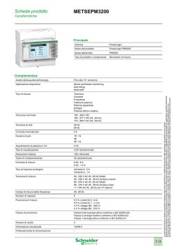
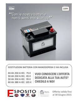
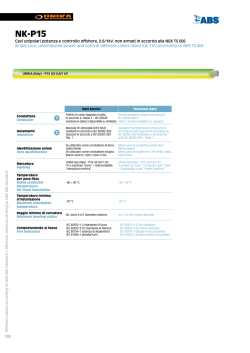
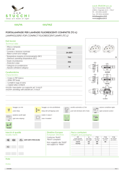
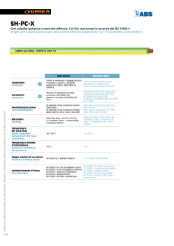
Scheda prodotto
ATV61HD30Y
Caratteristiche
Variatore 500/690V tri 30 kW
Principale
Gamma di prodotti
Altivar 61
Tipo di prodotto o componente
Variatore di velocità
Nome componente
ATV61
Potenza motore kW
22 kW 3 fasia 500 V
30 kW 3 fasia 690 V
Potenza motore hp
30 hp 3 fasia 575 V
Tensione nominale
500...690 V (- 15...10 %)
Numero di fasi della rete
3 fasi
Corrente di linea
28 Aper 600 V 3 fasi 22 kW / 30 hp
33 Aper 500 V 3 fasi 22 kW / 30 hp
34 Aper 690 V 3 fasi 22 kW / 30 hp
Filtro EMC
Filtro EMC livello 3
Stile assemblaggio
Con dissipatore di calore
Isc linea prospettiva
22 kA 3 fasi
Corrente transitoria massima
42 Aper 60 s 3 fasi
Frequenza di commutazione
nominale
4 kHz
Frequenza di commutazione
2,5...6 kHz regolabile
4...6 kHz con fattore di declassamento
Profilo di controllo motore
asincrono
Voltage/frequency ratio, 2 points
Voltage/frequency ratio, 5 points
Flux vector control without sensor, standard
Voltage/frequency ratio - Energy Saving, quadratic
U/f
Profilo contr. mot. sincrono
Vector control without sensor, standard
Compatibilità
CANopen
Modbus
Tipo di polarizzazione
Nessuna impedenzaper Modbus
Scheda opzioni
APOGEE FLN scheda comunicazione
BACnet scheda comunicazione
CC-Link scheda comunicazione
Scheda programmabile interna controller
DeviceNet scheda comunicazione
Ethernet/IP scheda comunicazione
Fipio scheda comunicazione
I/O extension card
Interbus-S scheda comunicazione
LonWorks scheda comunicazione
METASYS N2 scheda comunicazione
Modbus Plus scheda comunicazione
Modbus TCP scheda comunicazione
Modbus/Uni-Telway scheda comunicazione
Scheda multipompa
Profibus DP scheda comunicazione
Profibus DP V1 scheda comunicazione
Complementare
Applicazione prodotto
Motori asincroni
Motori sincroni
Limiti tensione alimentazione
425...759 V
Frequenza di alimentazione
50...60 Hz (- 5...5 %)
Limiti frequenza di rete
47.5...63 Hz
Corrente di uscita continua
32 Aa 4 kHz, 575 V 3 fasi
35 Aa 4 kHz, 500 V 3 fasi
35 Aa 4 kHz, 690 V 3 fasi
1/9
Le informazioni fornite in questo documento contengono descrizioni generali e/o caratteristiche tecniche delle prestazioni dei prodotti in esso riportati
Questa documentazione non è da intenedersi come esaustiva e non deve essere usata per determinare l'idoneità o l'affidabilità di questi prodotti per applicazioni specifiche dell'utente.
E' dovere di ogni utente o integratore eseguire la corretta e completa analisi dei rischi, valutazione e collaudo dei prodotti per quanto riguarda la specifica applicazione o uso.
Né Schneider Electric S.p.A. né alcuna delle sue affiliate o consociate, possono essere ritenuti responsabili per l'uso improprio delle informazioni contenute nel presente documento.
Per la protezione delle
Macchina di pompaggio e ventilazione
apparecchiature di rete e prodotti
a standard 19
Freq. uscita var. velocità
0.1...500 Hz
Gamma di velocità
1...100 in modo circuito aperto, senza segnale di velocità
Accuratezza velocità
+/- 10 % della velocità nominaleper 0,2 Tn a Tn variazione coppia senza segnale
velocità
Precisione di coppia
+/- 15 % in modo circuito aperto, senza segnale di velocità
Sovracoppia transitoria
130 % di coppia motore nominale, +/- 10 %per 60 s
Coppia frenante
<= 125 % con resistore freno
30 % senza resistore freno
Circuito di regolazione
Regolatore PI di frequenza
Compensazione slittamento motore
Regolabile
Qualsiasi carico automatico
Può essere soppresso
Non disponibile nel rapporto tensione/frequenza (2 o 5 punti)
Segnalazione locale
1 LED rosso presenza di tensione unità
Tensione di uscita
<= tensione alimentatore
Isolamento
Tra terminali di potenza e controllo
Tipo di cavi
Con kit IP21 o IP31 : 3-trefolo cavo IECa 40 °C, rame 70 °C PVC
Senza kit di montaggio : 1-trefolo cavo IECa 45 °C, rame 70 °C PVC
Senza kit di montaggio : 1-trefolo cavo IECa 45 °C, rame 90 °C XLPE/EPR
Con kit 1 tipoUL : 3-trefolo cavo UL 508a 40 °C, rame 75 °C PVC
Collegamento elettrico
AI1-/AI1+, AI2, AO1, R1A, R1B, R1C, R2A, R2B, LI1...LI6, PWR morsetto 2,5 mm² /
AWG 14
L1/R, L2/S, L3/T, U/T1, V/T2, W/T3, PC/-, PO, PA/+, PA, PB morsetto 50 mm² / AWG
1/0
Coppia di serraggio
L1/R, L2/S, L3/T, U/T1, V/T2, W/T3, PC/-, PO, PA/+, PA, PB 12 N·m / 102,2 lb.in
AI1-/AI1+, AI2, AO1, R1A, R1B, R1C, R2A, R2B, LI1...LI6, PWR 0.6 N·m
Alimentazione
Alimentazione interna per potenziometro di riferimento (da 1 a 10 kOhm) 10.5 V CC
+/- 5 %, <= 10 mAper protezione sovraccarico e da cortocircuito
Alimentazione interna 24 V CC (21...27 V), <= 200 mAper protezione sovraccarico e
da cortocircuito
Alimentazione esterna 24 V CC (19...30 V), 30 W
Numero ingressi analogici
2
Tipo di ingresso analogico
AI1-/Al1+ tensione differenziale bipolare +/- 10 V CC, tensione ingresso 24 V max,
risoluzione 11 bit + segno
AI2 corrente configurabile con software 0...20 mA, impedenza 242 Ohm, risoluzione
11 bit
AI2 tensione configurabile con software 0...10 V CC, tensione ingresso 24 V max,
impedenza 30000 Ohm, risoluzione 11 bit
Durata campionatura
Analog input AI1-/Al1+ 2 ms, +/- 0,5 ms
Analog input Al2 2 ms, +/- 0,5 ms
Analog output AO1 2 ms, +/- 0,5 ms
Ingresso digitale LI1...LI5 2 ms, +/- 0,5 ms
Ingresso digitale LI6 (se configurato come ingresso logico) 2 ms, +/- 0,5 ms
Precisione
AI1-/Al1+ +/- 0,6 % per una variazione di temperaturadi 60 °C
AI2 +/- 0,6 % per una variazione di temperaturadi 60 °C
AO1 +/- 1 % per una variazione di temperaturadi 60 °C
Errore linearità
AI1-/Al1+ +/- 0,15% di valore max
AI2 +/- 0,15% di valore max
AO1 +/- 0,2 %
Numero uscite analocighe
1
Tipo uscita analogica
AO1 corrente configurabile con software, range uscite analogiche 0...20 mA,
impedenza 500 Ohm, risoluzione 10 bit
AO1 uscita logica configurabile mediante software 10 V, <= 20 mA
AO1 tensione configurabile con software, range uscite analogiche 0...10 V CC,
impedenza 470 Ohm, risoluzione 10 bit
Numero uscite digitali
2
Tipo di uscita digitale
(R1A, R1B, R1C) logica relè configurabile NO/NC, durata elettrica 100000 cicli
(R2A, R2B) logica relè configurabile NO, durata elettrica 100000 cicli
Tempo di risposta
<= 100 ms in STO (Safe Torque Off)
R1A, R1B, R1C <= 7 ms, tolleranza +/- 0,5 ms
R2A, R2B <= 7 ms, tolleranza +/- 0,5 ms
Corrente di commutazione minima
Logica relè configurabile 3 mAa 24 V CC
Massima corrente di commutazione
R1, R2 su resistivo carico, 5 Aa 250 V CA, cos phi = 1, L/R = 0 ms
R1, R2 su resistivo carico, 5 Aa 30 V CC, cos phi = 1, L/R = 0 ms
R1, R2 su induttivo carico, 2 Aa 250 V CA, cos phi = 0,4, L/R = 7 ms
R1, R2 su induttivo carico, 2 Aa 30 V CC, cos phi = 0,4, L/R = 7 ms
Numero ingressi digitali
7
2/9
Tipo di ingresso digitale
(LI1...LI5) programmabile, 24 V CC, limiti tensione <= 30 V, con PLC livello 1,
impedenza 3500 Ohm
(LI6) configurabile con interruttore, 24 V CC, limiti tensione <= 30 V, con PLC livello 1,
impedenza 3500 Ohm
(LI6) sonda PTC configurabile con interruttore, 0...6, impedenza 1500 Ohm
(PWR) ingresso di sicurezza, 24 V CC, limiti tensione <= 30 V, impedenza 1500 Ohm
Logica ingresso digitale
LI1...LI5 logica positiva (sorgente), < 5 V (stato 0), > 11 V (stato 1)
LI1...LI5 logica negativa (corrente), > 16 V (stato 0), < 10 V (stato 1)
LI6 (se configurato come ingresso logico) logica negativa (corrente), > 16 V (stato 0),
< 10 V (stato 1)
LI6 (se configurato come ingresso logico) logica positiva (sorgente), < 5 V (stato 0), >
11 V (stato 1)
Rampe accel./decel.
Adattamento automatico rampa se si supera potere d'interruz, mediante resistore
Regolabile linearmente e separatamente da 0,01 a 9000 s
S, U o personalizzato
Frenatura di arresto
Con iniezione DC
Tipo di protezione
Comando contro superamento del limite di velocità
Comando contro perdita fase ingresso
Comando interruzione sul circuito di controllo
Comando interruzione fase di ingresso
Comando sovratensione alimentazione
Comando sottotensione alimentazione
Comando sovracorrente tra fasi uscita e messa a terra
Comando protezione surriscaldamento
Comando sovratensioni sul bus CC
Comando rimozione alimentazione
Comando cortocircuito tra le fasi del motore
Comando protezione termica
Motore interruzione fase motore
Motore rimozione alimentazione
Motore protezione termica
Resistenza di isolamento
> 1 mOhma 500 V CC per un minuto a massa
Risoluzione frequenza
Ingresso analogico 0,024/50 Hz
Unità display 0,1 Hz
Tipo di connettore
1 RJ45per Modbus su lato anteriore
1 RJ45per Modbus sul morsetto
SUB-D 9 maschio su RJ45per CANopen
Interfaccia fisica
2 cavi RS 485per Modbus
Trama di trasmissione
RTUper Modbus
Velocità di trasmissione
20 kbps, 50 kbps, 125 kbps, 250 kbps, 500 kbps, 1 Mbpsper CANopen
4800 bps, 9600 bps, 19200 bps, 38,4 Kbpsper Modbus sul morsetto
9600 bps, 19200 bpsper Modbus su lato anteriore
Formato dati
8 bit, 1 arresto, parità pariper Modbus su lato anteriore
8 bit, parità dispari o nessuna parità configurabileper Modbus sul morsetto
Numero di indirizzi
1...247per Modbus
1...127per CANopen
Metodo di accesso
Slaveper CANopen
Segnale
CE
Posizione di funzionamento
Verticale +/- 10 gradi
Peso prodotto
30 kg
Larghezza
240 mm
Altezza
420 mm
Profondità
236 mm
Ambiente
Livello di rumore
59.9 dB conforme a 86/188/EEC
Resistenza dielettrica
3110 V CC tra terminali di terra e alimentazione
5345 V CC tra terminali di controllo e alimentazione
Compatibilità elettromagnetica
Test immunità radiofrequenza condotta conforme a IEC 61000-4-6 livello 3
Prova di immunità ai transitori veloci / burst conforme a IEC 61000-4-4 livello 4
Test immunità scarica elettrostatica conforme a IEC 61000-4-2 livello 3
Test immunità ai campi elettromagnetici irradiati a radiofrequenza conforme a IEC
61000-4-3 livello 3
Test immunità cali di tensione e interruzioni conforme a IEC 61000-4-11
Norme di riferimento
EN 55011 classe A gruppo 2
EN 61800-3 ambienti 1 categoria C3
EN 61800-3 ambienti 2 categoria C3
EN/IEC 61800-3
3/9
EN/IEC 61800-5-1
IEC 60721-3-3 gruppo 3C2
UL tipo 1
Certificazioni prodotto
CSA
C-Tick
DNV
GOST
NOM 117
UL
Grado di inquinamento
3 conforme a EN/IEC 61800-5-1
3 conforme a UL 840
Grado di protezione IP
IP20 sulla parte superiore senza piastra di chiusura copertura conforme a EN/IEC
60529
IP20 sulla parte superiore senza piastra di chiusura copertura conforme a EN/IEC
61800-5-1
IP21 conforme a EN/IEC 60529
IP21 conforme a EN/IEC 61800-5-1
IP41 sulla parte superiore conforme a EN/IEC 60529
IP41 sulla parte superiore conforme a EN/IEC 61800-5-1
IP54 sulla parte inferiore conforme a EN/IEC 60529
IP54 sulla parte inferiore conforme a EN/IEC 61800-5-1
Resistenza alle vibrazioni
1,5 mm picco-picco (F = 3...13 Hz) conforme a EN/IEC 60068-2-6
1 gn (F = 13...200 Hz) conforme a EN/IEC 60068-2-6
Resistenza agli shock
15 gnper 11 ms conforme a EN/IEC 60068-2-27
Umidità relativa
5...95 % senza condensa conforme a IEC 60068-2-3
5...95 % senza caduta verticale di gocce d'acqua conforme a IEC 60068-2-3
Temperatura di funzionamento
-10...50 °C senza riduzione
50...60 °C con fattore di declassamento
Temperatura di stoccaggio
-25...70 °C
Altitudine di funzionamento
<= 1000 m senza riduzione
1000...2260 m con declassamento corrente dell'1 % per 100 m
Mounting Recommendations
Depending on the conditions in which the drive is to be used, its installation will require certain precautions and the use of appropriate
accessories.
Install the unit vertically:
●
●
Avoid placing it close to heating elements
Leave sufficient free space to ensure that the air required for cooling purposes can circulate from the bottom to the top of the
unit.
Clearance
Mounting Types
Type A Mounting
4/9
Type B Mounting
Type C Mounting
By removing the protective blanking cover from the top of the drive, the degree of protection for the drive becomes IP 20.
The protective blanking cover may vary according to the drive model (refer to the user guide).
Specific Recommendations for Mounting the Drive in an Enclosure
Ventilation
To ensure proper air circulation in the drive:
●
●
Fit ventilation grilles.
Ensure that there is sufficient ventilation. If there is not, install a forced ventilation unit with a filter. The openings and/or fans
must provide a flow rate at least equal to that of the drive fans (refer to the product characteristics).
●
Use special filters with IP 54 protection.
●
Remove the blanking cover from the top of the drive.
Dust and Damp Proof Metal Enclosure (IP 54)
The drive must be mounted in a dust and damp proof enclosure in certain environmental conditions: dust, corrosive gases, high humidity
with risk of condensation and dripping water, splashing liquid, etc.
This enables the drive to be used in an enclosure where the maximum internal temperature reaches 50°C.
Wiring Diagram Conforming to Standards EN 954-1 Category 1, IEC/EN 61508 Capacity SIL1, in Stopping Category 0 According to IEC/EN
60204-1
Three-Phase Power Supply with Upstream Breaking via Contactor
A1
ATV61 drive
KM1 Contactor
5/9
L1
DC choke
Q1 Circuit-breaker
Q2 GV2 L rated at twice the nominal primary current of T1
Q3 GB2CB05
S1, XB4 B or XB5 A pushbuttons
S2
T1
100 VA transformer 220 V secondary
(1)
Line choke (three-phase); mandatory for ATV61HC11Y…HC80Y drives (except when a special transformer is used (12-pulse)).
(2)
For ATV61HC50N4, ATV61HC63N4 and ATV61HC50Y…HC80Y drives, refer to the power terminal connections diagram.
(3)
Fault relay contacts. Used for remote signalling of the drive status.
(4)
Connection of the common for the logic inputs depends on the positioning of the SW1 switch. The above diagram shows the
internal power supply switched to the “source” position (for other connection types, refer to the user guide).
(5)
There is no PO terminal on ATV61HC11Y…HC80Y drives.
(6)
Optional DC choke for ATV61H•••M3, ATV61HD11M3X…HD45M3X and ATV61H075N4…HD75N4 drives. Connected in place of
the strap between the PO and PA/+ terminals. For ATV61HD55M3X…HD90M3X, ATV61HD90N4…HC63N4 drives, the choke is
supplied with the drive; the customer is responsible for connecting it. For ATV61W•••N4 and ATV61W•••N4C drives, the DC choke
is integrated.
(7)
Software-configurable current (0…20 mA) or voltage (0…10 V) analog input.
(8)
Reference potentiometer.
NOTE: All terminals are located at the bottom of the drive. Fit interference suppressors on all inductive circuits near the drive or
connected on the same circuit, such as relays, contactors, solenoid valves, fluorescent lighting, etc.
Wiring Diagram Conforming to Standards EN 954-1 Category 1, IEC/EN 61508 Capacity SIL1, in Stopping Category 0 According to IEC/EN
60204-1
Three-Phase Power Supply with Downstream Breaking via Switch Disconnector
A1
ATV61 drive
L1
DC choke
Q1 Circuit-breaker
Q2 Switch disconnector (Vario)
(1)
Line choke (three-phase), mandatory for ATV61HC11Y…HC80Y drives (except when a special transformer is used (12-pulse)).
(2)
For ATV61HC50N4, ATV61HC63N4 and ATV61HC50Y…HC80Y drives, refer to the power terminal connections diagram.
(3)
Fault relay contacts. Used for remote signalling of the drive status.
(4)
Connection of the common for the logic inputs depends on the positioning of the SW1 switch. The above diagram shows the
internal power supply switched to the “source” position (for other connection types, refer to the user guide).
(5)
There is no PO terminal on ATV61HC11Y…HC80Y drives.
(6)
Optional DC choke for ATV61H•••M3, ATV61HD11M3X…HD45M3X and ATV61H075N4…HD75N4 drives. Connected in place of
the strap between the PO and PA/+ terminals. For ATV61HD55M3X…HD90M3X, ATV61HD90N4…HC63N4 drives, the choke is
supplied with the drive; the customer is responsible for connecting it. For ATV61W•••N4 and ATV61W•••N4C drives, the DC choke
is integrated.
(7)
Software-configurable current (0…20 mA) or voltage (0…10 V) analog input.
(8)
Reference potentiometer.
NOTE: All terminals are located at the bottom of the drive. Fit interference suppressors on all inductive circuits near the drive or
6/9
connected on the same circuit, such as relays, contactors, solenoid valves, fluorescent lighting, etc.
Wiring Diagram Conforming to Standards EN 954-1 Category 3, IEC/EN 61508 Capacity SIL2, in Stopping Category 0 According to IEC/EN
60204-1
Three-Phase Power Supply, Low Inertia Machine, Vertical Movement
A1
ATV61 drive
A2
Preventa XPS AC safety module for monitoring emergency stops and switches. One safety module can manage the “Power
Removal” function for several drives on the same machine. In this case, each drive must connect its PWR terminal to its + 24 V via
the safety contacts on the XPS AC module. These contacts are independent for each drive.
F1
Fuse
L1
DC choke
Q1 Circuit-breaker
S1
Emergency stop button with 2 contacts
S2
XB4 B or XB5 A pushbutton
(1)
Power supply: 24 Vdc or Vac, 115 Vac, 230 Vac.
(2)
S2: resets XPS AC module on power-up or after an emergency stop. ESC can be used to set external starting conditions.
(3)
Requests freewheel stopping of the movement and activates the “Power Removal” safety function.
(4)
Line choke (three-phase), mandatory for and ATV61HC11Y…HC80Y drives (except when a special transformer is used (12-pulse)).
(5)
The logic output can be used to signal that the machine is in a safe stop state.
(6)
For ATV61HC50N4, ATV61HC63N4 and ATV61HC50Y…HC80Y drives, refer to the power terminal connections diagram.
(7)
Fault relay contacts. Used for remote signalling of the drive status.
(8)
Connection of the common for the logic inputs depends on the positioning of the SW1 switch. The above diagram shows the
internal power supply switched to the “source” position (for other connection types, refer to the user guide).
(9)
Standardized coaxial cable, type RG174/U according to MIL-C17 or KX3B according to NF C 93-550, external diameter
2.54 mm /0.09 in., maximum length 15 m / 49.21 ft. The cable shielding must be earthed.
(10) There is no PO terminal on ATV61HC11Y…HC80Y drives.
(11) Optional DC choke for ATV61H•••M3, ATV61HD11M3X…HD45M3X and ATV61H075N4…HD75N4 drives. Connected in place of
the strap between the PO and PA/+ terminals. For ATV61HD55M3X…HD90M3X, ATV61HD90N4…HC63N4 drives, the choke is
supplied with the drive; the customer is responsible for connecting it. For ATV61W•••N4 and ATV61W•••N4C drives, the DC choke
is integrated.
(12) Software-configurable current (0…20 mA) or voltage (0…10 V) analog input.
(13) Reference potentiometer.
NOTE: All terminals are located at the bottom of the drive. Fit interference suppressors on all inductive circuits near the drive or
connected on the same circuit, such as relays, contactors, solenoid valves, fluorescent lighting, etc.
Wiring Diagram Conforming to Standards EN 954-1 Category 3, IEC/EN 61508 Capacity SIL2, in Stopping Category 1 According to IEC/EN
60204-1
Three-Phase Power Supply, High Inertia Machine
7/9
A1
ATV61 drive
A2
(5)
Preventa XPS ATE safety module for monitoring emergency stops and switches. One safety module can manage the "Power
Removal” safety function for several drives on the same machine. In this case the time delay must be adjusted on the drive
controlling the motor that requires the longest stopping time. In addition, each drive must connect its PWR terminal to its + 24 V
via the safety contacts on the XPS ATE module. These contacts are independent for each drive.
F1
Fuse
L1
DC choke
Q1 Circuit-breaker
S1
Emergency stop button with 2 contacts
S2
XB4 B or XB5 A pushbutton
(1)
Power supply: 24 Vdc or Vac, 115 Vac, 230 Vac.
(2)
Requests controlled stopping of the movement and activates the “Power Removal” safety function.
(3)
Line choke (three-phase), mandatory for ATV61HC11Y…HC80Y drives (except when a special transformer is used (12-pulse)).
(4)
S2: resets XPS ATE module on power-up or after an emergency stop. ESC can be used to set external starting conditions.
(5)
The logic output can be used to signal that the machine is in a safe state.
(6)
For stopping times requiring more than 30 seconds in category 1, use a Preventa XPS AV safety module which can provide a
maximum time delay of 300 seconds.
(7)
For ATV61HC50N4, ATV61HC63N4 and ATV61HC50Y…HC80Y drives, refer to the power terminal connections diagram.
(8)
Fault relay contacts. Used for remote signalling of the drive status.
(9)
Connection of the common for the logic inputs depends on the positioning of the SW1 switch. The above diagram shows the
internal power supply switched to the “source” position (for other connection types, refer to the user guide).
(10) Standardized coaxial cable, type RG174/U according to MIL-C17 or KX3B according to NF C 93-550, external diameter
2.54 mm/0.09 in., maximum length 15 m/49.21 ft. The cable shielding must be earthed.
(11) Logic inputs LI1 and LI2 must be assigned to the direction of rotation: LI1 in the forward direction and LI2 in the reverse direction.
(12) There is no PO terminal on ATV61HC11Y…HC80Y drives.
(13) Optional DC choke for ATV61H•••M3, ATV61HD11M3X…HD45M3X and ATV61H075N4…HD75N4 drives. Connected in place of
the strap between the PO and PA/+ terminals. For ATV61HD55M3X…HD90M3X, ATV61HD90N4…HC63N4 drives, the choke is
supplied with the drive; the customer is responsible for connecting it. For ATV61W•••N4 and ATV61W•••N4C drives, the DC choke
is integrated.
(14) Software-configurable current (0…20 mA) or voltage (0…10 V) analog input.
(15) Reference potentiometer.
NOTE: All terminals are located at the bottom of the drive. Fit interference suppressors on all inductive circuits near the drive or
connected on the same circuit, such as relays, contactors, solenoid valves, fluorescent lighting, etc.
Derating Curves
The derating curves for the drive nominal current (In) depend on the temperature, the switching frequency and the mounting type (A, B or
C). For intermediate temperatures (e.g. 55°C), interpolate between 2 curves.
8/9
X
Switching frequency
NOTE: Above 50ºC, the drive should be fitted with a control card fan kit.
9/9
© Copyright 2026 Paperzz