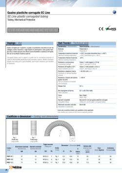
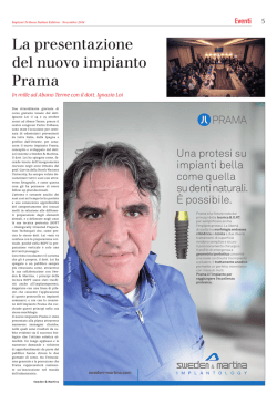
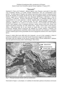
Tachogenerator GT 9.06L/420 K GTB 9.06L/420 K Tachogenerator (Description on page 2) Dynamo tachymétrique (Description, voir page 2) Generador tacométrico (Descripción en la pág. 3) Dinamo tachimetrica (Descrizione a pag. 4) Takometergenerator (Deskrivning sid. 5) EWN-Bestell-Nr./Order No.: 610.41185/21f Betriebsanleitung/Instructions Ausgabe/Edition: 12.92 DEUTSCH Allgemeiner Hinweis Zu beachten sind die Angaben und Anweisungen in allen gelieferten Betriebs- und sonstigen Anleitungen. Dies ist zur Vermeidung von Gefahren und Schäden unerläßlich! Eine zusätzliche Sicherheitsinformation (gelb) liegt bei, die ergänzende Angaben zur Sicherheit für elektrische Maschinen und Geräte enthält. Diese Sicherheitsanleitung ist deshalb auch eine Ergänzung für alle weiteren noch gelieferten Betriebs- und sonstigen Anleitungen. Tutti i diritti riservati. All rätt förbehålles. Alle Rechte vorbehalten. All rights reserved. Tous droits réservés. Reservados todos los derechos. Weiterhin sind die jeweils geltenden nationalen, örtlichen und anlagespezifischen Bestimmungen und Erfordernisse zu berücksichtigen! Sonderausführungen undBauvarianten können in technischen Details abweichen! Bei eventuellen Unklarheiten wird dringend empfohlen, unter Angabe von Typbezeichnung und Fertigungsnummer beim Hersteller rückzufragen, oder die Instandhaltungsarbeiten von einem der SIEMENS - Servicezentren durchführenzulassen. Beschreibung Anwendungsbereich Der Gleichstrom-Tachogenerator wird zur Drehzahlistwerterfassung bei Ein- und Mehrquadrantantrieben eingesetzt. Anbau an elektrische Maschinen B-seitig ohne gesonderte Kupplung. Arbeitsweise und Aufbau Der Tachogenerator entspricht den VDE-Bestimmungen. Der Tachogenerator hat Außenpolerregung durch Dauermagnete. Der Tacholäufer gibt eine drehrichtungsabhängige Gleichspannung ab. Im Tachokommutator ist zur Erhöhung der Kommutator- und Bürstenstandzeit eine Silberspur eingebettet. Bei laufender Antriebsmaschine liegt an den Klemmen bzw. Wickelenden des Tachogenerators Spannung. Technische Daten (siehe Fig. 5) HINWEIS:Der Vorsatz "Nenn-" wird in allen Zusammensetzungen durch den Vorsatz "Bemessungs-" ersetzt (s. DIN VDE 0530, Teil 1). Außerdem ist der Begriff Isolierstoffklasse durch Wärmeklasse ersetzt! Instandhaltung Überprüfung: Kontrolle von Bürsten- und Kommutatorzustand jeweils bei Wartung der Hauptmaschine (nach 3000 bis 5000 h). Maximale Bürstenstandzeit ca. 20 000 - 30 000 h bei 1000/min. Bürstenwechsel: Bürstenwechsel durchführen, wenn Restlänge nach Fig. 4 erreicht ist. Bürstenapparat und Kommutator von Bürstenstaub säubern, Tachogenerator ausblasen. Neue Kohlebürste (8.90) einsetzen.Nach außen gebogene Nase (N) am Bürstenkontaktbügel muß in den Schlitz hinter dem oberen Quersteg der Bürstenführung einhaken (Fig. 2). Siemens AG 1980 Instandsetzung Demontage Ständer GT 9.06L/420 K (Fig. 1): Haubenbefestigungsschrauben (8.88/ 8.91) herausdrehen, Haube vorsichtig abnehmen. Durch die Haube geführte Anschlußleitung an den Steckverbindungen (V) trennen. Kohlebürsten axial ausklinken. Ständer nach Lösen der zwei M5-Zylinderschrauben (8.89) abziehen. Ständer GTB 9.06L/420 K (Fig. 1): Anschlußstecker (8.82) nach Lösen der M3-Arretierungsschraube (Z) abziehen. Schrauben (8.91) zur Befestigung der Haube herausdrehen, Haube abnehmen. Kohlebürsten axial ausklinken. Ständer nach Lösen der zwei M5-Zylinderschrauben (8.89) abziehen. Läufer GT 9.06L/420 K, GTB 9.06L/420 K (Fig. 1, 2): M6-Befestigungsschraube (8.85) herausschrauben. Stahlstift "G" (4,8 mm x 24 mm) bis zum Anschlag in die Antriebswelle einstecken (zum Schutz der Zentrierung im Wellenende). An Stelle der Befestigungsschraube eine M8-Schraube (S) (Mindestlänge 30 mm) eindrehen und dadurch Läufer vom konischen Sitz auf der Antriebswelle (Kegel 1:10) abdrücken. Mitdrehen des Läufers durch Halten am Sechskant (SW 19) der Doppelkonusnabe verhindern. Montage (s. Fig. 1) Der Tacholäufer wird mit der Doppelkonusnabe gemäß Skizze auf das konische Wellenende A der Antriebsmaschine geschoben und mit einer Innensechskantschraube M6 (8.85-Anziehdrehmoment 10 Nm) befestigt. Maximal zulässige Rundlaufabweichung des Kommutators: 0,04 mm. Danach wird der Ständer am Zentrierrand des Lagerschildes (6.20) oder am Flansch der Zwischenanbauten (z. B. Drehmelder-Meßgetriebe) montiert. Nach der Ständermontage werden die Kohlebürsten von der Haubenseite her radial in die Bürstenführung eingesetzt. Die nach außen gebogene Nase (N) am Bürsten-Kontaktbügel (Fig. 4) muß dabei in den Schlitz hinter dem oberen Quersteg der Bürstenführung einhaken (Fig. 2). Ständer und Läufer des Tachogenerators sind aufeinander abge- stimmt; deshalb nur gemeinsam (gepaart) auswechseln. Elektrischer Anschluß GT 9.06L/420 K (Fig. 3): Elektrischer Anschluß erfolgt über Steckverbindungen (V) an die Anschlußpunkte 2A1 (Plus*) und 2A2 (Minus*). Anschlußleitung durch Verschraubung (Pg7) in der Haube führen. Auf freie Lage der Leitungen unter der Haube achten, um Schleifen am Kommutator zu vermeiden. GTB 9.06L/420 K (Fig. 3):Elektrischer Anschluß erfolgt über Anschlußstecker (8.82) außen am Gehäuse. Anschlußstecker nach Lösen der M3Arretierungsschraube (Z) abziehen. Anschlußplatte mit Bügelklemmen (W) aus Anschlußstecker nehmen (Schnappsitz). Anschlußleitung durch Verschraubung führen und an Bügelklemmen 2A1 (Plus*) und 2A2 (Minus*) anschließen. Beim Einsetzen der Anschlußplatte (um 180° drehbar) auf richtige Lage der Messerkontakte achten und Leitungen vorsichtig zurückziehen. * bei Rechtslauf des Antriebes 1 ENGLISH / FRANÇAIS General note Attention should be paid to the information contained in all operating and other instructions supplied. This is indispensable to avoid danger and risks of damage. Additional safety information (yellow) including supplementary data on the safety of electrical equipment is enclosed. These safety instructions therefore also supplement all further operating and other instructions supplied. Moreover, the applicable national, local and plant-specific regulations and requirements should be taken into account. Special designs and type versions might differ in the technical details. If there are any problems, it is strongly recommended to contact the manufacturer stating the type designation and serial number, or have repairs carried out by one of the Siemens service centers. Description Application The direct-current tachogenerator is used to measure the actual value of the speed of single and multiple-quadrant drives. It is attached to the nondrive end of electrical machines without a separate coupling. Mode of operation, construction Rotors GT 9.06L/420 K, GTB 9.06L/420 K (Figs. 1, 2): Screw out the M6 mounting bolt (8.85). Insert the steel pin "G" (4.8 mm x 24 mm) up to the stop in the motor shaft (to protect the centering spigot in the shaft end). Instead of the mounting bolt, turn in an M8 bolt (S) (minimum length 30 mm) and thus force off the rotor from the conical seat on the shaft (taper 1:10). Prevent the rotor from turning by holding the hexagon (width a cross flats 19 mm) of the twin cone shaft. Assembly (see Fig. 1) The tachogenerator rotor is fitted onto the tapered shaft end A of the main machine by means of the double taper-socketed shaft as shown in the drawing and secured in place with a hexagonal bolt M6 (8.85) (tightening torque 10 Nm). Maximum permissible run-out of the commutator: 0.04 mm. The stator is positioned on the centering edge of the end shield (6.20) or on the flange of the intermediate units (e.g. synchrogear assembly). After fitting the stator, the brushes are inserted in the brush box radially from the cover. The nose (N), which is bent outwards and fitted on the brush contact stirrup (Fig. 4), must engage in the slot behind the top crosspiece of the box (Fig. 2). The stator and rotor of the tachogenerator are coordinated to each other and must therefore only be replaced jointly (i.e. as a pair). Electrical connection GT 9.06L/420 K (Fig. 3): The electrical connection is made via the plug connectors (V) to the connection points 2A1 (plus*) and 2A2 (minus*). Enter the connecting lead through the screw gland (steel conduit thread Pg7) in the cover. See that the leads lie clear under the cover in order to prevent them dragging on the commutator. The tachogenerator is in accordance with VDE specifications. The tachogenerator has a stationary permanent-magnet field system. The tachogenerator rotor produces a direct voltage, the polarity of which is dependent on the direction of rotation. A silver track is embedded in the tachocommutator for increasing the commutator and brush lives. GTB 9.06L/420 K (Fig. 3): The electrical connection is made via the plug (8.82) outside on the casing. Slacken the M3 mounting bolt (Z), then withdraw the plug. Remove the connecting plate together with the Uterminals (W) from the plug (snap-in seat). Enter the connecting lead through the screw gland and connect it to the U-terminals 2A1 (plus*) and 2A2 (minus*). When inserting the connecting plate (revolvable by 180°), pay attention to the correct position of the plate contacts and pull back the leads carefully. When the main machine is running on load, a voltage is present at the terminals or the winding ends of the tachogenerator. * with clockwise rotation of the drive Technical data (s. Fig. 5) Maintenance Checks: Inspect the brush and commutator condition during the maintenance of the main machine (after 3000 to 5000 h). Maximum service life of brushes is up to approx. 20,000-30,000 h at 1000 rev/m. Brush replacement: Replace the brushes (see Fig.4). Clean the brushgear and the commutator of carbon dust. Clean the tachogenerator with compressed air, insert the new brushes (8.90). The nose (N), which is bent outwards and fitted on the brush-contact stirrup, must engage in the slot behind the top crosspiece of the box (Fig. 2). Repair Dismantling Stator GT 9.06L/420 K (Fig. 1): Screw out the cover mounting bolts (8.88/8.91) and lift off the cover carefully. Detach the lead, entered through the cover, from the plug connectors (V). Disengage the brushes axially. Slacken the two M5 cap screws (8.89), then withdraw the stator. Stator GTB 9.06L/420 K (Fig. 1): Slacken the M3 mounting bolt (Z), then withdraw the plug (8.82). Turn out the cover mounting bolts (8.91) then remove the cover. Disengage the brushes axially. Slacken the two M5 cap screws (8.89), then withdraw the stator. 2 FRANÇAIS Remarque générale Afin d’assurer laprotection des personnes et d’éviter toutdégât matériel, il est impératif de respecter les indications contenues dans toutes les instructions de service et dans tous les autres éléments de documentation transmis avec le produit. Les règles de sécurité applicables aux matériels électriques jointes (sur papier jaune) doivent être utilisées en complément de l’ensemble de la documentation. Toutes les prescriptions et exigences nationales, locales ou spécifiques à l’installation doivent être respectées. Les machines deréalisation spéciale (version, forme de construction) peuvent différer quant aux détails techniques. En cas de doute à ce sujet, il est instamment recommandé de contacter l’agence Siemens compétente en indiquant la désignation de type et le numéro de fabrication, ou de recourir aux centres de S.A.V. Siemens pour effectuer les travaux de maintenance. FRANÇAIS / ESPAÑOL Raccordement életrique Description Domaine d'utilisation La dynamo tachymétrique est utilisée pour la saisie de la vitesse instantanée des entraînements uniquadrants et multiquadrants. Elle se monte sur les machines électriques côté N, sans accouplement séparé. Constitution et mode de fonctionnement La dynamo tachymétrique est conforme aux prescriptions VDE. Elle a une excitation par aimants permanents fixés sur le stator. L’induit à courant continu délivre une tension continue fonction du sens de rotation. Une piste en argent est intégrée dans le collecteur de la dynamo tachymétrique afin d'augmenter la durée de vie du collecteur et des balais. GT 9.06L/420 K (fig. 3): le raccordement électrique se fait par languettes et clips (V) aux connexions 2A1 (positive*) et 2A2 (négative*). Faire passer les conducteurs par le presse-étoupe (Pg7) dans le capot; veiller à ce qu’ils soient posés librement sous le capot, afin d’éviter qu’ils ne frottent contre le collecteur. GTB 9.06L/420 K (fig. 3): le raccordement a lieu au moyen du connecteur (8.82) à l’extérieur de la carcasse. Dévisser la vis de fixation M3 (Z) et retirer le connecteur. Extraire de ce dernier la plaque portant les bornes (W) (fixation par encliquetage). Faire passer les conducteurs par le presse-étoupe et les raccorder aux bornes 2A1 (positive*) et 2A2 (négative*). Lors de la mise en place de la plaque à bornes (pouvant être tournée de 180°), veiller à ce que les broches de contacts soient en position correcte et tendre les conducteurs avec précaution. lorsque la machine principale tourne, les bornes ou les extrémités de bobine de la dynamo sont sous tension. * pour rotation à droite de l'entraînement Caractéristiques techniques (voir fig. 5) NOTA Le terme "nominal" est remplacé dans toutes ces acceptions par le terme "assigné". En outre, l’expression "classe d’isolement" est remplacée par l’expression "classe de température". ESPAÑOL Entretien Contrôles Contrôler l’état des balais et du collecteur lors de l’entretien de la machine principale (au bout de 3 000 à 5 000 h). Durée de vie maximale des balais : env. 20 000 à 30 000 h à 1 000 tr/min. Renouvellement des balais(voir fig. 4) Enlever la poussière de balai de l’unité de balais et du collecteur. Passer la dynamo au jet d’air comprimé. Mise en place des balais neufs : l’étrier de contact comporte une languette (N) recourbée vers l’extérieur. Celle-ci doit venir s’engager dans la fente située derrière la traverse supérieure de la cage (fig. 2). Remise en état Démontage Stator GT 9.06L/420 K (fig. 1): dévisser les vis de fixation du capot (8.88/ 8.91) et retirer le capot avec précaution. Défaire les connexions par clips et languettes (V) des conducteurs de raccordement passant par le capot. Décliqueter les balais dans le sens axial. Dévisser les deux vis à tête cylindrique M5 (8.89) et extraire le stator. Stator GTB 9.06L/420 K (fig. 1): dévisser la vis de fixation M3 (Z) et retirer le connecteur (8.82). Dévisser les vis de fixation du capot (8.91) et enlever le capot. Décliqueter les balais dans le sens axial. Retirer le stator après avoir dévissé les deux vis à tête cylindrique M5 (8.89). Rotors GT 9.06L/420 K, GTB 9.06L/420 K (fig. 1, 2): dévisser la vis de fixation M6 (8.85). Engager à fond la pige en acier (G) 4,8 mm x 24 mm dans l’arbre du moteur (pour protéger le trou taraudé de bout d’arbre). Visser une vis M8 (S) (longueur minimale 30 mm) à la place de la vis de fixation, afin de dégager le rotor de son siège conique sur l’arbre moteur (conicité 1/10). Empêcher le rotor de tourner en le retenant au niveau du six pans (clé de 19). Montage (voir fig. 1) Emmancher le rotor de la dynamo par son arbre à double alésage conique sur le bout d’arbre conique (A) de la machine principale suivant le croquis, et le fixer à l’aide d’une vis à six pans creux M6 (8.85) (couple de serrage 10 Nm). Excentricité maximale admissible du collecteur: 0,04 mm. Monter ensuite le stator dans le centrage du flasque palier (6.20) ou sur la bride des éléments intermédiaires rapportés (par ex. réducteur de synchromachine). Après le montage du stator, introduire les balais dans leur cage, en sens radial par le côté capot. La languette (N), recourbée vers le haut, de l’étrier de contact du balais (fig. 4) doit alors venir s’engager dans la fente située derrière la traverse supérieure de la cage (fig. 2). Le stator et le rotor de la dynamo tachymétrique sont adaptés l’un à l’autre. Ils doivent toujours être remplacés conjointement. Indicación general Se han de observar los datos e instrucciones que figuran en todas las instrucciones de servicio y demás informaciones suministradas. Esto es indispensable para evitar peligros y daños. Se adjunta una información adicional de seguridad (amarilla) conteniendo datos complementarios de seguridad para el material eléctrico. Estas instrucciones de seguridad son un suplemento de todas las demás instrucciones de servicio y otras, y forman parte de las mismas. También se tendrán en cuenta lasdeterminaciones y exigencias nacionales, locales y las específicas de la aplicación. Las ejecuciones especiales y lasvariantes constructivas pueden diferir en detalles técnicos. En caso de algún eventual inconveniente se recomienda expresamente preguntar al fabricante indicando el tipo y el número de fabricación o que un centro de service SIEMENS realice la reparación. Descripción Margen de aplicación El generador tacométrico de corriente continua se emplea para registrar los valores efectivos de las velocidades de giro de los accionamientos de uno o más cuadrantes. Se monta en el lado B de las máquinas eléctricas, sin necesidad de acoplamiento especial. Funcionamiento y constitución El generador cumple las prescripciones VDE. El generador tacométrico tiene excitación de polos exteriores mediante imanes permanentes. El inducido suministra una tensión continua, dependiente del sentido de giro. El colector de la tacodinamo tiene una rodadura de plata para prolongar la vida útil del colector y de las escobillas. Si la máquina principal marcha, los bornes y los extremos de las bobinas del generador tacométrico estarán bajo tensión. Datos técnicos (véase la fig. 5) 3 ESPAÑOL Conservación ITALIANO Note generali Pruebas:Comprobar el estado de las escobillas y del colector junto con el mantenimiento de la máquina principal (después de unas 3000 a 5000 h de servicio). Duración máxima de las escobillas: unas 20000 a 30000 h aprox. a 1000/min. Cambio de escobillas: Renovar las escobillas (fig. 4). Retirar los restos de escobillas y limpiar los portaescobillas y el colector. Soplar con aire comprimido el generador tacométrico. Colocar las nuevas escobillas (8.90). La lengüeta (N) del estribo de contacto de las escobillas debe encajar en la ranura que hay detrás del nervio transversal superior del portaescobillas (fig. 2). Reparación Desmontaje Estator GT 9.06L/420 K (fig. 1): Soltar los tornillos de fijación de la caperuza (8.88/8.91) y quitarla con cuidado. Deshacer las uniones por enchufe (V) de la línea de conexión que atraviesa la caperuza. Desenganchar axialmente las escobillas. Soltar los dos tornillos M5 (8.89) y sacar el estator. Estator GTB 9.06L/420 K (fig. 1): Para quitar el suplemento conector (8.82) soltar el tornillo M3 (Z). Aflojar los tornillos de fijación de la caperuza (8.91) y quitarla. Desenganchar axialmente las escobillas. Soltar los dos tornillos M5 (8.89) y sacar el estator. Rotores GT 9.06L/420 K, GTB 9.06L/420 K (figs. 1, 2): Soltar el tornillo de fijación M6 (8.85). Introducir la espiga de acero "G" (4,8mm x 24mm) en el eje del motor hasta el tope (para proteger el punto de centraje en el extremo del eje). Enroscar un tornillo M8 (S) (longitud mínima 30 mm) en el taladro de donde se ha sacado el tornillo de fijación y, girándolo, desprender el rotor del muñón cónico del eje del motor (cono 1:10). Impedir que el rotor gire con el tornillo, agarrando para ello el perfil hexagonal del cubo del rotor (ancho de Ilave 19). Montaje (véase la figs. 1) El rotor se encaja, con su eje de doble cono, sobre el muñón cónico (A) de la máquina principal, como puede verse en la figura; se fija con el tornillo de hexágono interior M6 (8.85), con un par de apriete de 10 Nm. Defecto de redondez máximo admisible del colector: 0,04 mm. A continuación, se monta el estator junto al borde de centraje del escudo (6.20) del cojinete o sobre la brida de los equipos intermedios (p. ej.: transmisión del avisador de giro). Después de montar el estátor, se insertan radialmente las escobillas por el lado de la caperuza, en el portaescobillas. La lengüeta (N) curvada hacia afuera del estribo de contacto de las escobillas (fig. 4) debe encajar en la ranura que hay detrás del nervio transversal superior del portaescobillas (fig. 2). Estátor y rotor del generador tacométrico están ajustados entre si; recambiarlos, por ello, solo conjuntamente. Conexión eléctrica GT 9.06L/420 K (fig. 3): La conexión eléctrica se efectúa a través de uniones por enchufe (V) en los puntos 2A1 (positivo*), y 2A2 (negativo*). Introducir el cable en la caperuza a través de la atornilladura (Pg7). Cuidar de que los cables no queden sueltos bajo la caperuza para que no rocen con el colector. GTB 9.06L/420 K (fig. 3): La conexión eléctrica se efectúa a través del conector (8.82) exterior a la carcasa. Para quitar el conector soltar el tornillo M3 (Z). Sacar la placa de conexión con los bornes (W) (encajados). Meter el cable por la atornilladura y conectarlo a los bornes 2A1 (positivo*) y 2A2 (negativo*). AI colocar la placa de conexión (girable en 180°), observar la correcta posición de las cuchillas y retirar los cables con cuidado. * al girar el accionamiento a derechas Osservare le indicazioni contenute in tutte le istruzioni d’uso fornite e nelle altre istruzioni per evitare pericoli e danni. In allegato troverete ulteriori avvertenze di sicurezza (in giallo), contenenti indicazioni relative alla sicurezza di apparecchi elettrici. Tali avvertenze di sicurezza costituiscono un’integrazione a tutte le istruzioni d’uso o di altro tipo fornite. Vanno inoltre rispettate le norme ed esigenze nazionali, locali e specifiche dell’impianto. Esecuzioni speciali e varianti costruttive possono discostarsi in particolari tecnici. Nel caso di eventuali difficoltà, si prega di rivolgersi al costruttore, indicando il tipo e il numero di matricola, oppure di far effettuare i lavori di manutenzione da uno dei centri di service della SIEMENS. Descrizione Campo d'impiego La dinamo tachimetrica a corrente cóntinua serve a rilevare il valore istantaneo negli azionamenti ad uno o più quadranti. Essa viene installata su macchine elettriche, lato B, senza giunti particolari. Modo di funzionamento e struttura La dinamo corrisponde alle norme VDE. La dinamo tachimetrica ha eccitazione a poli esterni mediante magneti permanenti. L’indotto eroga una tensione continua dipendente dal senso di rotazione. Nel collettore tachimetrico è inserita una pista in argento per elevare la durata del collettore e delle spazzole. Quando la macchina principale funziona, i morsetti o le estremità dell’avvolgimento della dinamo tachimetrica sono sotto tensione. Dati tecnici (fig. 5) NOTA: il concetto "nominale" é stato sostituito dal concetto "di taratura" (sec. DIN VDE 0530, parte 1). Il concetto "Classe d'isolamento" é stato sostituito dal concetto "Classe termica" . Manutenzione Ispezione: Controllare lo stato delle spazzole e del collettore ogni volta che viene effettuata la manutenzione della macchina principale (dopo 3000-5000 ore). Durata massima delle spazzole: ca. 20000-30000 h a 1000 giri/min. Sostituzione delle spazzole: Effettuare la sostituzione delle spazzole (ved. fig. 4). Pulire l'unitá spazzole ed il collettore dalla polvere lasciata dalle spazzole, soffiare via la polvere dalla dinamo. Applicare la nuova spazzola (8.90). Il lobo (N) rivolto verso l’esterno della staffa di contatto delle spazzole deve agganciarsi nella fessura dietro la costolatura trasversale superiore del guidaspazzola (fig. 2). Riparazione Smontaggio: Statore GT 9.06L/420 K (fig. 1): togliere con precauzione la calotta dopo aver svitato le viti (8.88/8.91) che la fissano. Sfilare dai morsetti (V) il cavetto che attraversa la calotta. Sganciare le spazzole estraendole assialmente. Estrarre lo statore dopo aver svitato le due viti a testa cilindrica M5 (8.89). Statore GTB 9.06L/420 K (fig. 1): sfilare il connettore dopo (8.82) aver svitato la vite di fissaggio M3 (Z). Svitare le viti (8.91) che fissano la calotta, e togliere quest’ultima. Sganciare assialmente le spazzole. Estrarre lo statore dopo aver svitato le due viti M5 a testa cilindrica (8.89). Rotore GT 9.06L/420 K, GTB 9.06L/420 K (fig. 1, 2): svitare le viti di fissaggio M6 (8.85). Infilare nell’albero del motore, fino al riscontro, lo spinotto d’acciaio "G" (4,8 mm x 24 mm) (per assicurare il centraggio 4 ITALIANO / SVENSKA sull’estremità dell’albero). Al posto della vite di fissaggio avvitare una vite M8 (S) (lunghezza minima 30 mm), spingendo così fuori dalla sede conica sull’albero del motore il rotore (conicità 1:10). Trattenendo il dado esagonale (SW 19) sul mozzo del rotore, impedire che il rotore giri. Montaggio (fig. 1) Il rotore della dinamo viene calettato con il mozzo a doppio cono sull’estremità d’albero conica (A) della macchina principale, come indica lo schizzo, e qui viene fissato con una vite ad esagono cavo M6 (8.85) (coppia di serraggio 10 Nm). Oscillazione radiale massima ammessa del commutatore: 0,04 mm. Poi viene montato lo statore sul bordo di centraggio dello scudo del cuscinetto (6.20) oppure sulla flangia di dispositivi eventualmente frapposti (p. es. riduttore di misura per un sincro). Dopo che è stato montato lo statore, infilare le spazzole radialmente nei guidaspazzole, sul lato della calotta. Il lobo (N) della staffa di contatto della spazzola (fig. 4) deve agganciarsi nella fessura dietro la costolatura trasversale superiore del guidaspazzole (fig. 2). Statore e rotore della dinamo sono messi a punto reciprocamente, perciò la sostituzione dell’uno comporta automaticamente la sostituzione dell’altro. När huvudmaskinen roterar ligger spänning på takometergeneratorns klämmor resp. lindningsändar. Tekniska data (se fig. 5) Skötsel Kontroll:Kontroll av borstarna och kommutatorn genomföres vid översyn av huvudmaskinen (efter ca. 3000-5000 h). Maximal livslängd hos borstarna, ca. 20 000 - 30 000 h vid 1000/min (fig. 4). Borstarna urtages, borstrester avlägsnas, borstapparaten och kommutatorn rengöres från damm från borstarna, takometergeneratorn urblåses och ny borste (8.90) insättes. Den utåt böjda klacken (N) på kontaktbygeln måste haka in i slitsen bakom det övre tvärstaget på borststyrningen (fig. 2). Reparation Collegamento elettrico GT 9.06L/420 K (fig. 3): l’allacciamento viene fatto innestando i terminali nei punti 2A1 (positivo*) e 2A2 (negativo*), dopo aver introdotto il cavetto nella calotta attraverso il bocchettone pressacavo Pg7. Fare attenzione a disporre la parte libera del cavetto, che rimane dentro la calotta, in modo che non tocchi il commutatore. GTB 9.06L/420 K (fig. 3): l’allacciamento è realizzato mediante la spina (8.82) all’esterno della custodia. Sfilare il connettore dopo aver svitato la vite di fissaggio M3 (Z). Estrarre dal connettore la piastrina di attacco (fissata a scatto) assieme ai morsetti a staffa (W). Introdurre il cavetto attraverso il bocchettone e allacciarlo ai morsetti 2A1 (positivo*) e 2A2 (negativo*). Nell’applicare la piastrina di attacco (spostabile di 180°), si faccia attenzione che la posizione dei contatti a coltello sia corretta, e tirare indietro con precauzione i conduttori. * con rotazione destrorsa dell'azionamento SVENSKA Allmänna anvisningar Följ alla uppgifter och anvisningar i medföljande driftsinstruktioner och övrig dokumentation. Då undviker du olycksrisker och skador. Ytterligare säkerhetsinformation (gul) medföljer. I denna finns kompletterande upplysningar rörande säkerheten för elektrisk utrustning. Denna säkerhetsanvisning gäller därför även som komplettering av alla övriga drifts- och andra anvisningar, inklusive sådana som ännu ej levererats. Följ dessutom gällandenationella, lokala ochanläggningsspecifika krav och bestämmelser. Specialutföranden och konstruktionsvarianter kan avvika i tekniska detaljer. Fråga tillverkaren så snart en oklarhet föreligger. Uppge därvid typbeteckningen och tillverkningsnumret eller låt alla reparationer utföras vid ett av Siemens servicecentra. Beskrivning Användningsområde Likströms-takometergeneratorn användes vid en- och flerkvadrantdrivanordningar för mätning av varvtalets ärvärde. Påbyggnad på B-sidan av elektriska maskiner utan särskild koppling. Funktionssätt och konstruktion Demontage Stator GT 9.06L/420 K (fig. 1): Fästskruvarna för huven (8.88/8.91) lossas och huven avtages försiktigt. Den genom huven förda anslutningsledningen lossas vid stickkontakterna (V). Borstarna lossas axiellt. De två M5-cylinderskruvarna (8.89) lossas och statorn avdrages. Stator GTB 9.06L/420 K (fig. 1): Stickkontakten (8.82) avtages efter det att fästskruven M3 (Z) lossats. Fästskruvarna för huven (8.91) lossas, huven avtages. Borstarna lossas axiellt. De två cylinderskruvarna M5 (8.89) lossas och statorn avdrages. Rotor GT 9.06L/420 K, GTB 9.06L/420 K (fig. 1, 2): M6-fästskruvarna (8.85) lossas. Stiftet "G" (4,8 mm x 24 mm) intryckes i motoraxeln till anslaget (som skydd för centreringen i axeländen). I stället för fästskruven inskruvas en M8-skruv (S) (min. längd 30 mm) varigenom rotorn kan lossas från sitt koniska säte på motoraxeln (kon 1:10). Vridning av rotorn förhindras genom fasthållning vid sexkanten (SW 19) hos rotorklacken. Montage (se fig. 1) Takometerrotorn skjutes med dubbelkonaxeln på den koniska axeländen (A) hos huvudmaskinen enl. skiss och fastsättes med en skruv med inre sexkant M6 (8.85) (Åtdragningsmoment 10 Nm). Rotations- avvikelse för kommutatorn max. 0,04 mm: Därefter monteras statorn på centeringsflänsen hos lagerskölden (6.20) eller på flänsen hos mellanpåbyggnaderna (t.ex. växel för varvtalsgivare). Efter statormontage införes borstarna radiellt i borststyrningen från huvsidan. Den utåt böjda klacken (N) på borstens kontaktbygel (fig. 4) måste därvid haka in i slitsen bakom det övre tvärstaget på borststyrningen (fig. 2). Takogeneratorns stator och rotor är anpassade till varandra; de utbytes därför endast gemensamt (parvis). Elektrisk anslutning GT 9.06L/420 K (fig. 3):Elektrisk anslutning sker över stickkontakter (V) till anslutningspunkterna 2A1 (plus*) och 2A2 (minus*). Anslutningsledningen införes i huven genom förskruvningen (Pg7). Se till att ledningarna ligger fritt under kåpan, så att de inte kan skrapa mot kommuntatorn. GTB 9.06L/420 K (fig. 3): Elektrisk anslutning sker över stickkontakt (8.82) utanpå huset. Stickkontakten avtages efter det att fästskruven M3 (Z) lossats. Anslutningsplattan med bygelklämmorna (W) urtages ur kontakten (snäppfäste). Anslutningsledningen föres genom förskruvningen och anslutes till bygelklämmorna 2A1 (plus*) och 2A2 (minus*). Vid insättning av anslutningsplattan (vridbar 180°) kontrolleras att knivkontakterna sitter riktigt, varefter ledningarna försiktigt drages tillbaka. * då drivanordningen roterar medurs Takometergeneratorn uppfyller VDE-bestämmelserna. Takometergeneratorn har ytterpolsmagnetisering genom permanenta magneter. Likströmsankaret avger en av rotationsriktningen beroende likspänning. Kommutatorns och borstarnas livslängd ökas av ett silverspår inbäddat i takokommutatorn. 5 DEUTSCH / ENGLISH / FRANÇAIS / ESPAÑOL / ITALIANO / SVENSKA GT 9.06L/420 K Ersatzteile, vom Werk lieferbar (siehe Bestellbeispiel) 8.80 8.82 8.83 8.87 8.90 8.92 8.93 6.20 Tachogenerator, komplett Anschlußstecker Dichtung Haube GT 9.06L/420 K Kohlebürste Haube GTB 9.06L/420 K Dichtung für die Haube 8.87 Y Spare parts, available from the works (see order example) 8.80 8.82 8.83 8.87 8.90 8.92 8.93 Tachogenerator, complete Plug Seal Cover GT 9.06L/420 K Carbon brush Cover GTB 9.06L/420 K Seal * Anziehdrehmoment * Tightening torque * Couple de serrage * Par de apriete * Coppia di serraggio * Åtdragningsmoment 8.88 */ 8.91 * A 1,5 ... 2 Nm 8.85 8.89 Pièces de rechange, livrables par l’usine (voir exemple de commande) 8.80 8.82 8.83 8.87 8.90 8.92 8.93 Dynamo tachymétrique Connecteur Joint Capot GT 9.06L/420 K Balai en charbon Capot GTB 9.06L/420 K Joint du capot 8.93 GTB 9.06L/420 K 6.20 Piezas de repuesto, GT 9.06L/420 K GTB 9.06L/420 K 8.92 suministrables de fábrica (véase ejemplo de pedido) 8.80 8.82 8.83 8.87 8.90 8.92 8.93 Generador tacométrico, completo Conector Junta Caperuza GT 9.06L/420 K Escobilla Caperuza GTB 9.06L/420 K Junta de la caperuza N 8.91 * 8.90 Ricambi, Y Y fornibili da fabbrica (ved. esempio di ordinazione) 8.80 8.82 8.83 8.87 8.90 8.92 8.93 Dinamo Connettore Guarnizione Calotta GT 9.06L/420 K Spazzola di carbone Calotta GTB 9.06L/420 K Guarnizione per la calotta A 8.85 8.89 A G S Reservdelar, tillgängliga från fabriken (se beställningsexempel) 8.80 8.82 8.83 8.87 8.90 8.92 8.93 Takometergenerator Stickkontakt Tätning Kåpan GT 9.06L/420 K Kolborste Kåpan GTB 9.06L/420 K Tätning Bestellbeispiel / Order example Exemple de commande / Ejemplo de pedido Esempio di ordinazione / Beställningsexempel GT 9.06L/420 K 8.90 Kohlebürsten 8.93 8.83 8.82 Fig. 1 Normteile sind nach Abmessung, Werkstoff und Oberfläche im freien Handel zu beziehen. Standard commercially available parts are to be purchased in accordance with the specified dimensions, material and surface finish. Les pièces normalisées peuvent être obtenues dans le commerce d’après leurs dimensions, le matériau et l’état de surface. Las piezas estándar se comprarán en los comercios del ramo según sus dimensiones, material y estado de la superficie. Le parti standard sono reperibili sul mercato secondo le dimensioni, il materiale e la finitura della superficie. Normerade detaljer kan erhållas i öppna handeln, och skall specificeras beträffande storlek, material och ytbehandling. 6 Fig. 2 8.85 8.88 8.89 8.91 DIN 84 DIN 6912 DIN 7985 DEUTSCH / ENGLISH / FRANÇAIS / ESPAÑOL / ITALIANO / SVENSKA GT 9.06L/420 K ohne / without / sans sin / senza / utan 8.87 N 8.85 V 8.89 8.90 8.88 * GTB 9.06L/420 K ohne / without / sans sin / senza / utan 8.92 8.90 A G S W V Y Z Wellenende der Antriebsmaschine Stahlstift M8-Schraube zum Abdrücken Klemme Flachstecker für Anschluß Silberlaufspur Arretierungsschraube A G S W V Y Z Shaft end of main machine Steel pin M8 bolt for extraction purposes Terminal Flat connecting plug Silver track Screw for terminal A G S W V Bout d’arbre de la machine principale Pige en acier Vis d’extraction M8 Borne Languettes des conducteurs de raccordement Piste en argent Vis de fixation Y Z 8.82 8.83 A 8.85 G S W V Y Z W Z 8.89 Extremo del eje de la máquina principal Espiga de acero Tornillo M8 para desmontar Borne Enchufe plano Rodadura de plata Tornillo de retención W A G S W V Y Z N 8.91 * A G S W V Y Z Estremità d’albero della macchina principale Spinotto d’acciaio Vite M8 per estrazione Morsetto Connettore piatto per collegamento Pista d'argento Vite d'arresto Axelände hos huvudmaskinen Stålstift M8-skruv för avdragning Anslutning Anslutningsledningen vid stickkontakten Silverspår Skruv för kopplingsplint Fig. 3 6 mm 9 mm N Restlänge der verbrauchten Kohlebürste = 6 mm Minimum permissible length of worn carbon brush = 6 mm Longueur résiduelle d’un balai usé = 6 mm Longitud min. de las escobillas gastadas 6 mm Lunghezza residua delle spazzole consumate = 6 mm Restlängd hos den förbrukade kolborsten 6 mm 8.90 Fig. 4 7 DEUTSCH / ENGLISH / FRANÇAIS / ESPAÑOL / ITALIANO / SVENSKA Technische Daten (bei Bemessungsdrehzahl und Bemessungsbürde, wenn nichts anderes angegeben) Technical data (at rated speed and rated burden unless otherwise specified) Caractéristiques techniques (sauf indication contraire, à la vitesse et à la résistance de charge assignées) Datos técnicos (referidos a la velocidad y la resistencia nominales, siempre que no se haya indicado lo contrario) Dati tecnici (con velocità e carico normali, se non è indicato diversamente) Tekniska data (vid märkvarvtal och märkbelastning, om ej annat angives) GT 9.06L/420 K GTB 9.06L/420 K Leerlauf-Gleichspannung / No-load DC voltage Tension continue à vide / Tensión continua nominal Tensione nominale continua / Märklikspänning 20 V Bemessungsstrom / Rated current Courant assigné / Intensidad nominal Corrente di taratura / Märkström 3,0 mA Bemessungsdrehzahl / Rated speed Vitesse assignée / Velocidad de giro nominal Velocità di taratura / Märkvarvtal 1000 Bemessungsbürde / Rated burden Résistance assignée de charge / Resistencia de carga nominal Carico di taratura / Märkbelastning 6,7 kΩ Spannungstoleranz / Voltage tolerance Tolérance de tension / Tolerancia para la tensión Tolleranza di tensione / Spänningstolerans ±5% Scheitelwelligkeit / Ripple factor Ondulation crête à crête / Ondulación entre crestas Ondulazioni di cresta / Överton-toppvärde Linearitätsfehler / Linearity error Erreur de linéarité / Error de linealidad Errore di linearità / Linearitetsfel Reversierfehler / Reversing error Erreur de marche dans les deux sens /Error de reversión Errore di inversione / Reverserfel /min rev/min tr/min rpm giri/min r/min ≤ 0,2 % der Spannung of the voltage de la tension de la tensión della tensione hos spänningen ≤ 0,2 % Drehzahlbereich / Speed range Plage de vitesse / Gama de velocidad Campo di velocità / Varvtalsområde 0 - 8000 Maximaler Strom / Maximum current Courant maximal / Intensidad máxima Corrente massima / Maximal ström Bauform / Type of construction Forme / Forma constructiva Forma costruttiva / Utförandeform Temperaturgang des Magnetsystems (kompensiert) Temperature range of the magnet system (compensated) Dérive en température du système magnétique (compensée) Respuesta en temperatura del sistema magnético (compensado) Andamento della temperatura del sistema magnetico (compensato) Magnetsystemets temperaturomfång (kompenserat) /min rev/min tr/min rpm giri/min r/min in beiden Richtungen in both directions dans les deux sens de rotation en ambas direcciones in entrambi i sensi di rotazione i båda rotationsriktningarna 30 mA Wärmeklasse / Temperature class Classe de température / Clase de aislamiento Classe termica / Isolationsklass Schutzart / Degree of protection Degré de protection / Clase de protección Grado di protezione / Kapslingsklass im gesamten Drehzahlbereich in the whole speed range sur toute la plage de vitesse para toda la gama de velocidad in tutto il campo di velocità över hela varvtalsområdet ≤ 0,15 % B IP 54 IP 68 mit Haube und bei entsprechenden Anbauverhältnissen with cover and appropriate mounting conditions avec capot et pour un montage approprié con caperuza y condiciones convenientes de montaje con cappa e condizioni di montaggio idonee med kåpa och motsvarande påbyggnadsförhållanden IM 5210 ± 0,05 % pro/per/pour/cada/per ogni/per 10 K Bei Messungen am Tachogenerator nur hochohmige Meßinstrumente (Ri ≥ 100 kΩ/V) verwenden. High-resistance measuring instruments only (Ri ≥ 100 kΩ/V) must be used for measurements on the tachogenerator. Pour les mesures effectuées sur la dynamo tachymétrique, utiliser uniquement des appareils de mesure à très grande résistance interne (Ri ≥ 100 kΩ/V). Para efectuar mediciones en el generador tacométrico, emplear solo instrumentos de gran resistancia interna (Ri ≥ 100 kΩ/V). Per effettuare misurazioni sulla dinamo tachimetrica devono esser impiegati solo strumenti di misura ad alta resistenza (Ri ≥ 100 kΩ/V) . Vid mätningar på takogeneratorn får endast högresistiva mätinstrument användas (Ri ≥ 100 kΩ/V). Fig. 5 Herausgegeben vom / Issued by Bereich Antriebs-, Schalt- und Installationstechnik / Drives and Standard Products Group Elektromotorenwerk Bad Neustadt (EWN) Postfach 1720, D-8740 Bad Neustadt an der Saale Siemens Aktiengesellschaft Änderungen vorbehalten Subject to change without prior notice Sous réserve de modifications Sujeto a modificaciones Ci riserviamo eventuali modifiche Förbehåll för ändringar EWN-Bestell-Nr. / Order No.: 610.41185/21f Bestell-Ort: EWN Printed in the Federal Republic of Germany AG 1292 MA 8 De-En-Fr-Sp-It-Sv
© Copyright 2026 Paperzz