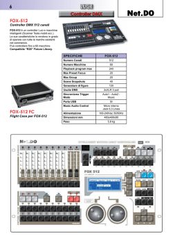
Schwenkbare LED-Leiste
LED Beam Moving Bar
BEAM-8/ WS
Bestellnummer 38.6960
BEDIENUNGSANLEITUNG
INSTRUCTION MANUAL
MODE D’EMPLOI
ISTRUZIONI PER L’USO
MANUAL DE INSTRUCCIONES
INSTRUKCJA OBSŁUGI
VEILIGHEIDSVOORSCHRIFTEN
SIKKERHEDSOPLYSNINGER
SÄKERHETSFÖRESKRIFTER
TURVALLISUUDESTA
ELECTRONICS FOR SPECIALISTS ELECTRONICS FOR SPECIALISTS ELECTRONICS FOR SPECIALISTS ELECTRONICS FOR SPECIALISTS
D
Deutsch . . . . . . . . . . . . . . . Seite
4
GB
English . . . . . . . . . . . . . . . Page
8
F
Français . . . . . . . . . . . . . . Page
12
I
Italiano . . . . . . . . . . . . . . . Pagina
16
E
Español . . . . . . . . . . . . . . . Página
20
PL
Polski . . . . . . . . . . . . . . . . Stronie
24
NL
Nederlands . . . . . . . . . . . . Pagina
28
DK
Dansk . . . . . . . . . . . . . . . . Sida
28
S
Svenska . . . . . . . . . . . . . . . Sidan
29
FIN
Suomi . . . . . . . . . . . . . . . . Sivulta
29
ELECTRONICS FOR SPECIALISTS ELECTRONICS FOR SPECIALISTS ELECTRONICS FOR SPECIALISTS ELECTRONICS FOR SPECIALISTS
3
D
A
CH
➀ Bedientasten und Anschlüsse
2. wenn nach einem Sturz oder Ähnlichem der
Verdacht auf einen Defekt besteht,
3. wenn Funktionsstörungen auftreten.
Geben Sie das Gerät in jedem Fall zur Reparatur
in eine Fachwerkstatt.
Schwenkbare LED-Leiste
Bitte lesen Sie diese Anleitung vor dem Betrieb
gründlich durch und heben Sie sie für ein späteres
Nachlesen auf.
● Ziehen
1 Einsatz- und Aufstellmöglichkeiten
Das BEAM-8 / WS dient zur Effektbeleuchtung, z. B.
auf Bühnen, in Diskotheken und Festsälen. Als
Lichtquelle sind 8 leistungsstarke weiße 10-WLEDs eingesetzt, die auf einem drehbaren Träger
montiert sind.
Das Lichteffektgerät ist für die Steuerung über ein
DMX-Lichtsteuergerät ausgelegt (14 oder 5 DMXSteuerkanäle). Es kann aber auch allein betrieben
werden, indem verschiedene Lichtshow-Programme automatisch oder musikgesteuert ablaufen.
Das Gerät kann frei auf einer ebenen Fläche
aufgestellt werden. Zur Montage kopfüber an einer
Traverse liegen zwei Schellen dabei. Diese in
jeweils zwei Löcher auf der Geräteunterseite
hineinstecken und durch Drehen der Bolzen im
Uhrzeigersinn fest verriegeln (bis zum Anschlag).
2
Hinweise
für den sicheren Gebrauch
Das Gerät entspricht allen relevanten Richtlinien
der EU und ist deshalb mit
gekennzeichnet.
WARNUNG Das Gerät wird mit lebensgefährlicher Netzspannung versorgt.
Nehmen Sie deshalb nie selbst Eingriffe am Gerät vor. Durch unsachgemäßes Vorgehen besteht die Gefahr
eines elektrischen Schlages.
● Verwenden
Sie das Gerät nur im Innenbereich
und schützen Sie es vor Tropf- und Spritzwasser,
hoher Luftfeuchtigkeit und Hitze (zulässiger Einsatztemperaturbereich 0 – 40 °C).
● Nehmen Sie das Gerät nicht in Betrieb oder ziehen
Sie sofort den Netzstecker aus der Steckdose,
1. wenn sichtbare Schäden am Gerät oder am
Netzkabel vorhanden sind,
4
Sie den Netzstecker nie am Kabel aus
der Steckdose, fassen Sie immer am Stecker an.
● Verwenden
Sie für die Reinigung des Gehäuses
nur ein trockenes, weiches Tuch, niemals Wasser oder Chemikalien. Für die Linsen kann auch
ein handelsübliches Glasreinigungsmittel verwendet werden.
● Wird
das Gerät zweckentfremdet, nicht sicher
montiert, nicht richtig angeschlossen, falsch
bedient oder nicht fachgerecht repariert, kann
keine Haftung für daraus resultierende Sachoder Personenschäden und keine Garantie für
das Gerät übernommen werden.
Soll das Gerät endgültig aus dem Betrieb
genommen werden, übergeben Sie es zur
umweltgerechten Entsorgung einem örtlichen Recyclingbetrieb.
3
Inbetriebnahme
1) Zur Stromversorgung das Gerät über die Netzbuchse POWER IN mit dem beiliegenden Netzkabel an eine Steckdose (230 V~ / 50 Hz)
anschließen. Den blauen POWERCON®-Stecker des Netzkabels nach dem Einstecken in
die Netzbuchse nach rechts drehen, bis er einrastet. Zum späteren Herausziehen den Sicherungsriegel am Stecker zurückziehen und den
Stecker nach links drehen.
2) Werden mehrere BEAM-8 / WS verwendet, kann
die Buchse POWER OUT des ersten Gerätes
mit der Netzbuchse POWER IN des zweiten
Gerätes verbunden werden. Dazu wird ein Netzkabel mit POWERCON®-Steckern (NAC-3FCB
und NAC-3FCA) benötigt. Das zweite Gerät
kann dann wieder mit dem dritten Gerät verbunden werden usw., bis alle Geräte in einer Kette
angeschlossen sind. Auf diese Weise lassen
sich maximal 40 Geräte zusammenschalten.
Die Buchse POWER OUT kann auch zur
Stromversorgung anderer (Lichteffekt-) Geräte
genutzt werden. Jedoch dürfen die Buchsen
POWER IN und POWER OUT nicht mit einem
Strom von mehr als 20 A belastet werden. Es
kann sonst durch die Überlastung ein Kurzschluss und Brand entstehen.
3) Das Lichteffektgerät mit dem Schalter POWER
einschalten. Das Display zeigt durch verschiedene Anzeigen das Rücksetzen und den Startvorgang an. Danach schaltet das Gerät den
zuletzt gespeicherten Betriebsmodus ein und
nach ca. 40 Sek. erlischt das Display (bis auf
einen blinkenden Punkt). Sobald eine der
Bedientasten MENU, DOWN, UP oder ENTER
gedrückt wird, leuchtet es wieder für ca. 40 Sek.
Nach dem Betrieb das Gerät mit der Schalter
POWER wieder ausschalten.
WARNUNG Blicken Sie nicht für längere Zeit
direkt in die Lichtquelle, das kann zu
Augenschäden führen.
Beachten Sie, dass sehr schnelle
Lichtwechsel bei fotosensiblen Menschen und Epileptikern epileptische
Anfälle auslösen können!
4
Die Bedientasten MENU, UP, DOWN und ENTER
dienen zum Auswählen des Betriebsmodus und
verschiedener Funktionen (Abb. 2). Das Display
zeigt dabei den Modus oder die Einstellung an.
Funktion
Betriebsmodus und
Einstellmöglichkeiten anwählen
UP
Einstellung von DMX-Adresse, Showprogramm,
DOWN Geschwindigkeit, Drehrichtung, Drehwinkel
Einstellung speichern und
ENTER
gewählte Funktion aktivieren
MENU
DMX-Betrieb
mit 14 Kanälen
UP
(ENTER)*
Lichtshow
= autom.
= musikgest.
DMX-Betrieb
mit 5 Kanälen
MENU
DOWN
D
Für den eigenständigen Betrieb stehen 22 Lichtshow-Programme (
…
) zur Verfügung.
Bei dem Programm 22 werden die Programme
1 – 21 und zusätzliche Programme nacheinander
durchlaufen. Für einen musikgesteuerten Ablauf die
Einstellung
wählen und die Lautstärke der
Musikanlage so hoch einstellen, dass das Showprogramm nach der Musik abläuft.
A
CH
4.2 Betrieb mit einem DMX-Steuergerät
Zur Bedienung über ein DMX-Lichtsteuergerät
(z. B. DMX-1440 oder DMX-510USB von „img
Stage Line“) verfügt das BEAM-8 / WS über 14
DMX-Steuerkanäle. Es lässt sich aber auch über
nur 5 Kanäle steuern, wenn die dann verfügbaren
Funktionen ausreichen oder am Lichtsteuergerät
keine 14 Kanäle mehr frei sind.
DMX ist die Abkürzung für Digital Multiplex und
bedeutet digitale Steuerung von mehreren DMXGeräten über eine gemeinsame Steuerleitung. Die
Funktionen der Kanäle und die DMX-Werte sind im
Kapitel 4.2.3 angegeben.
4.2.1 Anschluss
Für die DMX-Verbindung sind 3-polige XLR-Anschlüsse mit folgender Kontaktbelegung vorhanden:
Pin 1 = Masse, 2 = DMX-, 3 = DMX+
Bedienung
Taste
4.1 Eigenständiger Betrieb
MENU
DOWN
UP
(ENTER)*
Zum Anschluss sollten spezielle Kabel für die DMXSignalübertragung verwendet werden (z. B. Kabel
der CDMXN-Serie von „img Stage Line“). Bei Leitungslängen ab 150 m wird grundsätzlich das Zwischenschalten eines DMX-Aufholverstärkers empfohlen (z. B. SR-103DMX von „img Stage Line“).
1) Den Eingang DMX IN mit dem DMX-Ausgang
des Lichtsteuergerätes oder eines anderen
DMX-gesteuerten Gerätes verbinden.
2) Den Ausgang DMX OUT mit dem DMX-Eingang
des nächsten DMX-Gerätes verbinden. Dessen
Ausgang wieder mit dem Eingang des nachfolAblaufgeschwindigkeit
für
MENU
DOWN
UP
DOWN
UP
(ENTER)*
MENU
DOWN
UP
(ENTER)*
Drehwinkel
= programmgesteuert
Drehrichtung
entgegengesetzt
bei
MENU
DOWN
UP
MENU
DOWN
(ENTER)*
UP
(ENTER)*
* mit Taste ENTER Einstellung speichern
und gewählte Funktion aktivieren
➁ Einstellmöglichkeiten über das Menü
5
D
A
CH
genden DMX-Gerätes verbinden usw., bis alle
DMX-gesteuerten Geräte in einer Kette angeschlossen sind.
3) Um Störungen bei der Signalübertragung auszuschließen, sollte bei langen Leitungen bzw.
bei einer Vielzahl von hintereinandergeschalteten Geräten der DMX-Ausgang des letzten
DMX-Gerätes der Kette mit einem 120-ΩWiderstand (> 0,3 W) abgeschlossen werden:
In die DMX-Ausgangsbuchse einen entsprechenden Abschlussstecker (z. B. DLT-123 von
„img Stage Line“) stecken.
4.2.2 Anzahl der DMX-Kanäle
und Startadresse einstellen
Um alle am Lichtsteuergerät angeschlossenen
DMX-Geräte separat bedienen zu können, muss
jedes Gerät eine eigene Startadresse erhalten. Soll
der erste DMX-Kanal des BEAM-8 / WS vom Lichtsteuergerät z. B. über die DMX-Adresse 6 gesteuert werden, am Lichteffektgerät die Startadresse 6 einstellen. Die übrigen DMX-Kanäle des
BEAM-8 / WS sind dann automatisch den darauffolgenden Adressen zugeordnet. Beispiele mit verschiedenen Startadressen:
Anzahl
der DMXKanäle
5
14
Startadresse
1
6
12
1
8
112
5-Kanal-Betrieb
DMX-Kanal DMX-Wert Funktion
1
2
3
4
nächstmögliche Startvom BEAM-8 / WS
adresse für das nachfolbelegte Adressen
gende DMX-Gerät
1– 5
6
6 – 10
11
12 – 16
17
1 – 14
15
8 – 21
22
112 – 125
126
➂ DMX-Adressenbelegung des BEAM-8/WS
1) Die Taste MENU so oft drücken, bis das Display
für den 14-Kanal-Modus oder
für den 5-Kanal-Modus
anzeigt.
2) Mit der Taste UP oder DOWN die Startadresse
einstellen.
3) Mit der Taste ENTER die Einstellung speichern
und den DMX-Betrieb starten. Das Display
leuchtet jetzt ständig.
Das BEAM-8 / WS lässt sich nun über das
DMX-Steuergerät bedienen (DMX-Funktionen
siehe Tabellen im nächsten Kapitel 4.2.3). Beim
Empfang von DMX-Steuersignalen blinkt der
Punkt ganz rechts im Display.
Tipp: Werden zwei oder mehrere BEAM-8 / WS
synchron über dieselbe Startadresse gesteuert, die
Drehrichtung der LED-Leiste bei einem oder mehreren Geräten entgegengesetzt einstellen (
).
So drehen sich die LED-Leisten z. B. bei einem
Gerätepaar gegenläufig.
6
4.2.3 DMX-Kanäle und -Funktionen
000
001 – 255
Drehung der LED-Leiste:
programmgesteuert (Kanal 4)
Drehwinkel 0 ➞ 270°
000 – 255
Drehgeschwindigkeit
schnell ➞ sehr langsam
000
001 – 255
LEDs aus
dunkel ➞ hell
000 – 002
003 – 013
014 – 024
025 – 035
036 – 046
047 – 057
058 – 068
069 – 079
080 – 090
091 – 101
102 – 112
113 – 123
124 – 134
135 – 145
146 – 156
157 – 167
168 – 178
179 – 189
190 – 200
201 – 211
212 – 222
223 – 233
234 – 244
LEDs aus
Lauflichtprogramm 1
Lauflichtprogramm 2
Lauflichtprogramm 3
Lauflichtprogramm 4
Lauflichtprogramm 5
Lauflichtprogramm 6
Lauflichtprogramm 7
Lauflichtprogramm 8
Lauflichtprogramm 9
Lauflichtprogramm 10
Lauflichtprogramm 11
Lauflichtprogramm 12
Lauflichtprogramm 13
Lauflichtprogramm 14
Lauflichtprogramm 15
Lauflichtprogramm 16
Lauflichtprogramm 17
Lauflichtprogramm 18
Lauflichtprogramm 19
Lauflichtprogramm 20
Lauflichtprogramm 21
Programme 1 – 21 + zusätzliche Programme
Musiksteuerung
245 – 255
5
000 – 255
Ablaufgeschwindigkeit der Programme langsam ➞ schnell
5
14-Kanal-Betrieb
DMX-Kanal DMX-Wert Funktion
000
001 – 255
Drehung der LED-Leiste:
programmgesteuert (Kanal 13)
Drehwinkel 0 ➞ 270°
000 – 255
Drehgeschwindigkeit
schnell ➞ sehr langsam
3
000
001 – 255
LEDs aus
Dimmer dunkel ➞ hell
4
000 – 255
Helligkeit LED 1 dunkel ➞ hell
5
000 – 255
Helligkeit LED 2 dunkel ➞ hell
6
000 – 255
Helligkeit LED 3 dunkel ➞ hell
7
000 – 255
Helligkeit LED 4 dunkel ➞ hell
8
000 – 255
Helligkeit LED 5 dunkel ➞ hell
9
000 – 255
Helligkeit LED 6 dunkel ➞ hell
10
000 – 255
Helligkeit LED 7 dunkel ➞ hell
11
000 – 255
Helligkeit LED 8 dunkel ➞ hell
12
000
001 – 255
kein Stroboskop
Stroboskop langsam ➞ schnell
000 – 002
Steuerung über
die Kanäle 1 – 12
1
2
13
003 – 013
014 – 024
025 – 035
036 – 046
047 – 057
058 – 068
069 – 079
080 – 090
091 – 101
102 – 112
113 – 123
124 – 134
135 – 145
146 – 156
157 – 167
168 – 178
179 – 189
190 – 200
201 – 211
212 – 222
223 – 233
234 – 244
245 – 255
14
000 – 255
Lauflichtprogramm 1
Lauflichtprogramm 2
Lauflichtprogramm 3
Lauflichtprogramm 4
Lauflichtprogramm 5
Lauflichtprogramm 6
Lauflichtprogramm 7
Lauflichtprogramm 8
Lauflichtprogramm 9
Lauflichtprogramm 10
Lauflichtprogramm 11
Lauflichtprogramm 12
Lauflichtprogramm 13
Lauflichtprogramm 14
Lauflichtprogramm 15
Lauflichtprogramm 16
Lauflichtprogramm 17
Lauflichtprogramm 18
Lauflichtprogramm 19
Lauflichtprogramm 20
Lauflichtprogramm 21
Programme 1 – 21 + zusätzliche Programme
Musiksteuerung
Ablaufgeschwindigkeit der Programme langsam ➞ schnell
Technische Daten
D
Datenprotokoll: . . . . . . . . . DMX 512
A
Anzahl der DMX-Kanäle: . 14 oder 5
CH
Lichtquelle: . . . . . . . . . . . . 8 weiße LEDs
Leistungsaufnahme: . . . 10 W je LED
Abstrahlwinkel: . . . . . . . 3°
Drehwinkel der LED-Leiste: 270°
Stromversorgung: . . . . . . . 230 V~ / 50 Hz
Leistungsaufnahme: . . . . . max. 110 VA
Abmessungen (B × H × T): 1080 × 145 × 80 mm
Gewicht: . . . . . . . . . . . . . . 7,3 kg
beiliegendes Zubehör: . . . 2 × Montageschelle
1 × Netzkabel mit
POWERCON®und SchukoStecker
Änderungen vorbehalten.
Diese Bedienungsanleitung ist urheberrechtlich für
MONACOR ® INTERNATIONAL GmbH & Co. KG geschützt. Eine Reproduktion für eigene kommerzielle
Zwecke – auch auszugsweise – ist untersagt.
7
GB
➀ Control elements and connections
Moving LED Beam Bar
● Never
Please read these operating instructions carefully
prior to operation and keep them for later reference.
● For
1
● No
Applications and Setup Options
The BEAM-8 / WS can be used to create effect illumination, e. g. on stage, in discotheques or function
rooms. It features 8 powerful white 10 W LEDs,
mounted on a movable bar.
The light effect unit is designed for control via a
DMX light controller (14 or 5 DMX control channels), but it can also be operated on its own, running automatic or music-controlled light show programs.
The unit can be set up on an even surface. For
upside-down installation on a crossbar, two clamps
are provided: Insert each clamp in two holes located
on the bottom side of the unit and then turn the bolts
clockwise (to the stop) to securely lock the clamp.
2
Safety Notes
The unit corresponds to all relevant directives of
the EU and is therefore marked with .
WARNING The unit uses dangerous mains voltage. Leave servicing to skilled personnel only. Inexpert handling or
modification of the unit may result in
electric shock.
● The
unit is suitable for indoor use only. Protect it
against dripping water and splash water, high air
humidity and heat (admissible ambient temperature range: 0 – 40 °C).
● Do
not operate the unit and immediately disconnect the mains plug from the mains socket
1. if the unit or the mains cable is visibly damaged,
2. if a defect might have occurred after the unit
was dropped or suffered a similar accident,
3. if malfunctions occur.
In any case the unit must be repaired by skilled
personnel.
8
pull the mains cable to disconnect the
mains plug from the socket, always seize the plug.
cleaning only use a dry, soft cloth; never use
water or chemicals. For cleaning the lenses, a
standard glass cleaner may be used.
guarantee claims for the unit and no liability
for any resulting personal damage or material
damage will be accepted if the unit is used for
other purposes than originally intended, if it is not
safely installed, if it is not correctly connected or
operated, or if it is not repaired in an expert way.
If the unit is to be put out of operation
definitively, take it to a local recycling plant
for a disposal which is not harmful to the
environment.
3
Setting the Unit into Operation
1) For power supply, connect the mains jack
POWER IN of the unit to a mains socket
(230 V~/ 50 Hz) using the mains cable provided.
Insert the blue POWERCON® plug of the mains
cable into the mains jack, and then turn the plug
to the right until it engages. To remove the plug,
pull back the safety latch of the plug and turn the
plug to the left.
2) If multiple BEAM-8 / WS are used, the jack
POWER OUT of the first unit can be connected
to the mains jack POWER IN of the second unit.
For this, a mains cable with POWERCON®
plugs (NAC-3FCB and NAC-3FCA) is required.
The second unit can then be connected to the
third unit, etc. until all units are connected in a
chain. Thus, up to 40 units can be connected
with each other.
The jack POWER OUT may also be used to
provide power to other (light effect) units. However, the current load of the jacks POWER IN
and POWER OUT must not exceed 20 A. Otherwise, a short circuit and fire may occur due to
overload.
3) Use the POWER switch to switch on the light
effect unit. Various information will appear on
the display to indicate that the light effect unit is
being reset and started. Then the unit will switch
on the operating mode most recently saved;
after approx. 40 seconds, the display will extinguish (with the exception of a flashing dot).
When one of the control buttons MENU, UP,
DOWN or ENTER is pressed, the display will
light up for approx. 40 seconds again.
To switch off the unit after operation, use the
POWER switch.
WARNING To prevent damage to your eyes,
never look directly into the light
source for a longer period of time.
Please note that fast light changes
may trigger epileptic seizures with
photosensitive persons or persons
with epilepsy!
4
GB
For operation via a DMX light controller (e. g. DMX1440 or DMX-510USB from “img Stage Line”), the
BEAM-8 / WS is equipped with 14 DMX control
channels. The BEAM-8 / WS can also be controlled
via 5 channels if the functions provided by the
5-channel mode suffice or if less than 14 channels
are available at the light controller.
DMX stands for Digital Multiplex and means digital control of multiple DMX units via a common
control line. The functions of the channels and the
corresponding DMX values can be found in chapter
4.2.3.
4.2.1 Connection
For DMX connection, 3-pole XLR connections with
the following pin configuration are available:
pin 1 = ground, 2 = DMX-, 3 = DMX+
Operation
Use the control buttons MENU, UP, DOWN and
ENTER to select the operating mode and various
functions (fig. 2). The display will indicate the mode
or the setting.
Button
4.2 Operation with a DMX controller
Function
For the connection, special cables for DMX signal
transmission (e. g. cables of the CDMXN series
from “img Stage Line”) should be used. For cable
lengths exceeding 150 m, the insertion of a DMX
level matching amplifier (e. g. SR-103DMX from
“img Stage Line”) is recommended.
1) Connect the input DMX IN to the DMX output of
the light controller or of another DMX-controlled
unit.
MENU select operating mode and settings options
UP
set DMX address, show program, speed,
DOWN rotation direction, rotation angle
4.1 Independent operation
2) Connect the output DMX OUT to the DMX input
of the next DMX unit. Connect the output of the
latter DMX unit to the input of the following unit,
etc. until all DMX-controlled units are connected
in a chain.
For independent operation, 22 light show programs
(
…
) are available. With program 22, the
programs 1 – 21 and additional programs will run
one after the other. For a music-controlled program
run, select the setting
and adjust the volume
of the music system to such a level that the show
program runs in accordance with the music.
3) To prevent interference in signal transmission:
For long cables or for a great number of units
connected in series, terminate the DMX output
of the last DMX unit in the chain with a 120 Ω
resistor (> 0.3 W): Connect an appropriate terminating plug (e.g. DLT-123 from “img Stage
Line”) to the DMX output jack.
ENTER save setting and activate the function selected
DMX mode with
14 channels
MENU
DOWN
UP
(ENTER)*
Light show
= autom.
= music-ctrl.
DMX mode with
5 channels
MENU
DOWN
UP
(ENTER)*
MENU
DOWN
UP
DOWN
UP
(ENTER)*
Rotation direction
opposite for
Speed for
MENU
DOWN
UP
(ENTER)*
Rotation angle
= programcontrolled
MENU
DOWN
UP
(ENTER)*
MENU
DOWN
UP
(ENTER)*
* use the button ENTER to save the setting
and to activate the function selected
➁ Setting options via the menu
9
GB
4.2.2 Setting the number of DMX channels
and the start address
For separate control of all DMX units connected to
the light controller, each unit requires a start
address of its own. Example: If the first DMX channel of the BEAM-8 / WS is to be controlled by the
light controller via DMX address 6, set the start
address on the light effect unit to 6. The other DMX
channels of the BEAM-8 / WS will then be automatically assigned to the subsequent addresses.
Example for various start addresses:
Number
of DMX
channels
5
14
Start
address
1
6
12
1
8
112
Addresses used
by the
BEAM-8 / WS
1– 5
6 – 10
12 – 16
1 – 14
8 – 21
112 – 125
Next possible start
address for the subsequent DMX unit
6
11
17
15
22
126
4.2.3 DMX channels and DMX functions
5-channel mode
DMX
channel
1
2
3
➂ DMX address assignment of the BEAM-8/WS
1) Press the button MENU repeatedly until the display shows:
for the 14-channel mode or
for the 5-channel mode
4
2) Use the button UP or DOWN to set the start
address.
3) Press the button ENTER to save the setting and
to start the DMX mode. The display will light up
constantly.
The BEAM-8 / WS can now be operated via
the DMX controller (for the DMX functions,
please refer to the tables in chapter 4.2.3). A dot
will flash on the right of the display when DMX
signals are being received.
Hint: If two or more BEAM-8 / WS are synchronously controlled via the same start address, set
the rotation of the LED bars for one or more units to
opposite directions (
). Thus, with a pair of
units, one LED bar will rotate clockwise and the
other LED bar counter-clockwise.
10
5
DMX value Function
000
001 – 255
rotation of the LED bar:
program-controlled (channel 4)
rotation angle 0 ➞ 270°
000 – 255
rotation speed
fast ➞ very slow
000
001 – 255
LEDs off
dark ➞ bright
000 – 002
003 – 013
014 – 024
025 – 035
036 – 046
047 – 057
058 – 068
069 – 079
080 – 090
091 – 101
102 – 112
113 – 123
124 – 134
135 – 145
146 – 156
157 – 167
168 – 178
179 – 189
190 – 200
201 – 211
212 – 222
223 – 233
234 – 244
245 – 255
LEDs off
running light program 1
running light program 2
running light program 3
running light program 4
running light program 5
running light program 6
running light program 7
running light program 8
running light program 9
running light program 10
running light program 11
running light program 12
running light program 13
running light program 14
running light program 15
running light program 16
running light program 17
running light program 18
running light program 19
running light program 20
running light program 21
programs 1 – 21 + additional programs
music control
000 – 255
speed of the programs
slow ➞ fast
5
Specifications
GB
Data protocol: . . . . . . . . . . DMX 512
14-channel mode
DMX
channel
DMX value Function
000
001 – 255
rotation of the LED bar:
program-controlled (channel 13)
rotation angle 0 ➞ 270°
000 – 255
rotation speed
fast ➞ very slow
3
000
001 – 255
LEDs off
dimmer dark ➞ bright
4
000 – 255
brightness LED 1 dark ➞ bright
5
000 – 255
brightness LED 2 dark ➞ bright
6
000 – 255
brightness LED 3 dark ➞ bright
7
000 – 255
brightness LED 4 dark ➞ bright
8
000 – 255
brightness LED 5 dark ➞ bright
9
000 – 255
brightness LED 6 dark ➞ bright
10
000 – 255
brightness LED 7 dark ➞ bright
11
000 – 255
brightness LED 8 dark ➞ bright
12
000
001 – 255
no stroboscope
stroboscope slow ➞ fast
000 – 002
control via
the channels 1 – 12
1
2
Number of DMX channels: 14 or 5
Light source: . . . . . . . . . . . 8 white LEDs
Power consumption: . . . 10 W for each LED
Beam angle: . . . . . . . . . 3°
Rotation angle
of the LED bar: . . . . . . . . . 270°
Power supply: . . . . . . . . . . 230 V~ / 50 Hz
Power consumption: . . . . . 110 VA max.
Dimensions (W × H × D): . 1080 × 145 × 80 mm
Weight: . . . . . . . . . . . . . . . 7.3 kg
13
14
003 – 013
014 – 024
025 – 035
036 – 046
047 – 057
058 – 068
069 – 079
080 – 090
091 – 101
102 – 112
113 – 123
124 – 134
135 – 145
146 – 156
157 – 167
168 – 178
179 – 189
190 – 200
201 – 211
212 – 222
223 – 233
234 – 244
245 – 255
running light program 1
running light program 2
running light program 3
running light program 4
running light program 5
running light program 6
running light program 7
running light program 8
running light program 9
running light program 10
running light program 11
running light program 12
running light program 13
running light program 14
running light program 15
running light program 16
running light program 17
running light program 18
running light program 19
running light program 20
running light program 21
programs 1 – 21 + additional programs
music control
000 – 255
speed of the programs
slow ➞ fast
Accessories: . . . . . . . . . . . 2 × mounting clamp
1 × mains cable with
POWERCON® plug
and earthed plug
Subject to technical modification.
All rights reserved by MONACOR ® INTERNATIONAL
GmbH & Co. KG. No part of this instruction manual
may be reproduced in any form or by any means for
any commercial use.
11
F
B
CH
➀ Touches de commande et branchements
2. après une chute ou un cas similaire, vous avez
un doute sur lʼétat de lʼappareil,
3. des dysfonctionnements apparaissent.
Dans tous les cas, les dommages doivent être
réparés par un technicien spécialisé.
Barrette à LEDs orientable
Veuillez lire la présente notice avec attention avant
le fonctionnement et conservez-la pour pouvoir
vous y reporter ultérieurement.
1
Possibilités dʼutilisation
et de positionnement
La BEAM-8 / WS permet de créer des effets lumineux, par exemple sur scène, dans des discothèques et salles des fêtes. 8 LEDs blanches 10 W
puissantes sont la source lumineuse, elles sont
montées sur une barrette orientable.
Le jeu de lumière est conçu pour une gestion via
un contrôleur DMX (14 ou 5 canaux DMX). Il peut
également fonctionner seul : des programmes
Show différents défilent alors automatiquement ou
gérés par la musique.
Lʼappareil peut être posé librement sur une surface plane. Pour un montage sur une traverse, tête
à lʼenvers, deux colliers de montage sont livrés. Placez-les dans les deux trous sur la partie inférieure de
lʼappareil et en tournant les boulons dans le sens des
aiguilles dʼune montre, verrouillez (jusquʼà la butée).
2
débranchez jamais lʼappareil en tirant sur le
cordon secteur ; retirez toujours le cordon secteur en tirant la fiche.
● Pour
nettoyer le boîtier, utilisez uniquement un
chiffon sec et doux, en aucun cas, de produits
chimiques ou dʼeau. Pour les lentilles, vous pouvez également utiliser des produits de nettoyage
usuels pour verres.
● Nous
déclinons toute responsabilité en cas de
dommages matériels ou corporels résultants si
lʼappareil est utilisé dans un but autre que celui
pour lequel il a été conçu, sʼil nʼest pas monté
dʼune manière sûre, correctement utilisé ou nʼest
pas réparée par une personne habilitée, en
outre, la garantie deviendrait caduque.
Lorsque lʼappareil est définitivement retiré
du service, vous devez le déposer dans
une usine de recyclage adaptée pour
contribuer à son élimination non polluante.
Conseils dʼutilisation et de sécurité
Lʼappareil répond à toutes les directives nécessaires de lʼUnion européenne et porte donc le symbole .
AVERTISSEMENT Cet appareil est alimenté par
une tension dangereuse. Ne touchez jamais lʼintérieur de lʼappareil car, en cas de mauvaise manipulation, vous pourriez subir
une décharge électrique.
● Lʼappareil nʼest conçu que pour une utilisation en
intérieur. Protégez-le de tout type de projections
dʼeau, des éclaboussures, dʼune humidité élevée
de lʼair et de la chaleur (plage de température de
fonctionnement autorisée : 0 – 40 °C).
● Ne
faites pas fonctionner lʼappareil ou débranchez-le immédiatement du secteur lorsque :
1. des dommages visibles apparaissent sur lʼappareil ou sur le cordon secteur,
12
● Ne
3
Fonctionnement
1) Pour lʼalimentation, reliez lʼappareil, via la prise
secteur POWER IN et le cordon secteur livré, à
une prise 230 V~/50 Hz. Mettez la fiche POWERCON® bleue du cordon secteur dans la prise secteur et tournez-la vers la droite jusquʼà ce quʼelle
sʼenclenche. Pour pouvoir la retirer, tirez sur le
levier sur la fiche et tournez-la vers la gauche.
2) Si vous utilisez plusieurs BEAM-8 / WS, la prise
POWER OUT du premier appareil peut être
reliée à la prise secteur POWER IN du
deuxième appareil. Un cordon secteur avec
fiches POWERCON® (NAC-3FCB et NAC3FCA) est nécessaire. Vous pouvez relier
ensuite le deuxième appareil au troisième et
ainsi de suite jusquʼà ce que tous les appareils
soient reliés en une chaine. Il est ainsi possible
de brancher ensemble jusquʼà 40 appareils.
La prise POWER OUT peut également servir
pour lʼalimentation dʼautres appareils (jeux de
lumière). Les prises POWER IN et POWER
OUT ne doivent pas avoir une charge de courant de plus de 20 A. Sinon, la surcharge peut
engendrer un court-circuit et un incendie.
3) Allumez lʼappareil avec lʼinterrupteur POWER.
Lʼaffichage indique, par plusieurs messages, la
réinitialisation et le processus de démarrage.
Ensuite il commute sur le mode de fonctionnement dernièrement mémorisé et 40 secondes
après environ, lʼaffichage sʼéteint (sauf un point
clignotant). Dès quʼune des touches de commande MENU, DOWN, UP ou ENTER est activée, lʼaffichage sʼallume à nouveau pendant
40 secondes environ.
Après le fonctionnement, éteignez lʼappareil
avec lʼinterrupteur POWER.
AVERTISSEMENT Ne regardez jamais directement
la source de lumière, cela pourrait
causer des troubles de la vision.
Nʼoubliez pas que des changements très rapides de lumière
peuvent déclencher des crises
dʼépilepsie chez les personnes
photosensibles et épileptiques !
4
Utilisation
Les touches MENU, UP, DOWN et ENTER permettent de sélectionner le mode de fonctionnement et
différentes fonctions (schéma 2). Lʼaffichage indique le réglage ou le mode.
Touche Fonction
sélection du mode de fonctionnement
et des possibilités de réglage
UP
réglage de lʼadresse DMX, programme Show,
DOWN vitesse, sens de rotation, angle de rotation
mémorisation des réglages, activation de la
ENTER
fonction sélectionnée
MENU
Mode DMX
avec 14 canaux
MENU
DOWN
UP
(ENTER)*
MENU
DOWN
UP
(ENTER)*
UP
DOWN
UP
(ENTER)*
B
CH
4.2 Fonctionnement
avec un contrôleur DMX
Pour une gestion via un contrôleur DMX (par exemple DMX-1440 ou DMX-510USB de “img Stage
Line”), la BEAM-8 / WS dispose de 14 canaux de
commande DMX. Il est également possible de
nʼutiliser que 5 canaux si les fonctions disponibles
sont suffisantes ou si aucun des 14 canaux nʼest
plus disponible sur le contrôleur.
DMX est lʼabréviation de Digital Multiplex et
signifie commande digitale de plusieurs appareils
DMX via un câble commun de commande. Vous
trouverez les fonctions des canaux et les valeurs
DMX dans le chapitre 4.2.3.
4.2.1 Branchement
Pour la connexion DMX, des branchements XLR
3 pôles avec la configuration de contact suivante
sont prévus :
Pin 1 = masse, 2 = DMX-, 3 = DMX+
Pour le branchement, il est recommandé dʼutiliser
des câbles spécifiques pour la transmission de
signaux DMX (par exemple câbles des séries
CDMXN de “img Stage Line”). Pour des longueurs
de liaison à partir de 150 m, il est recommandé dʼinsérer un amplificateur DMX de signal (par exemple
SR-103DMX de “img Stage Line”).
Vitesse défilement
pour
MENU
DOWN
F
Pour le fonctionnement autonome, 22 programmes
Show (
…
) sont disponibles. Avec le programme 22, les programmes 1 à 21 et des programmes supplémentaires défilent les uns après
les autres. Pour un défilement géré par la musique,
sélectionnez le réglage
et réglez le volume de
la musique assez fort pour que le programme
Show défile selon la musique.
1) Reliez lʼentrée DMX IN à la sortie DMX du
contrôleur ou dʼun autre appareil géré par DMX.
Show
= automatique
= par la musique
Mode DMX
avec 5 canaux
4.1 Fonctionnement autonome
MENU
DOWN
UP
(ENTER)*
Angle de rotation
= à le programme
Inversion sens
de rotation
à
MENU
DOWN
UP
(ENTER)*
MENU
DOWN
UP
(ENTER)*
* avec la touche ENTER, mémorisez le réglage
et activez la fonction sélectionnée
➁ Possibilités de réglage via le menu
13
F
B
CH
2) Reliez la sortie DMX OUT à lʼentrée DMX du
prochain appareil DMX. Reliez sa sortie à lʼentrée de lʼappareil DMX suivant et ainsi de suite
de manière à ce que tous les appareils gérés
par DMX forment une chaîne.
3) Pour éviter les perturbations lors de la transmission du signal, il convient, pour de longs câbles
ou pour une multitude dʼappareils branchés les
uns derrière les autres, de terminer la sortie
DMX du dernier appareil DMX de la chaîne avec
une résistance 120 Ω (> 0,3 W) : mettez un bouchon (par exemple DLT-123 de “img Stage
Line”) dans la prise de sortie.
4.2.2 Réglage du nombre de canaux DMX
et de lʼadresse de démarrage
Pour pourvoir utiliser séparément tous les appareils
DMX reliés au contrôleur, il faut que chaque appareil aie une adresse de démarrage propre. Si le premier canal DMX de la BEAM-8 / WS doit être géré
par le contrôleur par exemple via lʼadresse DMX 6,
réglez lʼadresse de démarrage 6 sur le jeu de lumière. Les autres canaux DMX de la BEAM-8/ WS
sont automatiquement attribués aux adresses suivantes. Exemples avec différentes adresses de démarrage :
Nombre Adresse
Adresses
de canaux de démar- configurées pour
DMX
rage
la BEAM-8 / WS
1
1– 5
5
6
6 – 10
12
12 – 16
1
1 – 14
14
8
8 – 21
112
112 – 125
Mode 5 canaux
Canal DMX Valeur DMX Fonction
1
2
3
4
Adresse de démarrage
suivant possible pour
lʼappareil DMX suivant
6
11
17
15
22
126
➂ Configuration des adresses DMX de la BEAM-8/WS
1) Appuyez sur la touche MENU jusquʼà ce que
lʼaffichage indique
pour le mode 14 canaux ou
pour le mode 5 canaux
2) Avec la touche UP ou DOWN, réglez lʼadresse
de démarrage.
3) Avec la touche ENTER, mémorisez le réglage
et démarrez le mode DMX. Lʼaffichage brille en
continu.
La BEAM-8 / WS peut maintenant être utilisée
via le contrôleur DMX (fonctions DMX, voir
tableaux au chapitre 4.2.3). Lors de la réception
de signaux de commande DMX, le point à droite
sur lʼaffichage clignote.
Conseil : si deux ou plusieurs BEAM-8 / WS sont gérées de
manière synchrone via la même adresse de démarrage,
réglez le sens de rotation de la barrette de LEDs pour un ou
plusieurs appareils à lʼinverse (
). Les barrettes de
LEDs tournent alors, par exemple pour une paire dʼappareils, à contre sens.
14
4.2.3 Canaux DMX et fonctions DMX
000
001 – 255
rotation de la barrette de LEDs:
programmé (canal 4)
angle de rotation 0 ➞ 270°
000 – 255
vitesse de rotation
rapide ➞ très lent
000
001 – 255
LEDs éteintes
sombre ➞ clair
000 – 002
003 – 013
014 – 024
025 – 035
036 – 046
047 – 057
058 – 068
069 – 079
080 – 090
091 – 101
102 – 112
113 – 123
124 – 134
135 – 145
146 – 156
157 – 167
168 – 178
179 – 189
190 – 200
201 – 211
212 – 222
223 – 233
234 – 244
LEDs éteintes
programme lumière défilante 1
programme lumière défilante 2
programme lumière défilante 3
programme lumière défilante 4
programme lumière défilante 5
programme lumière défilante 6
programme lumière défilante 7
programme lumière défilante 8
programme lumière défilante 9
programme lumière défilante 10
programme lumière défilante 11
programme lumière défilante 12
programme lumière défilante 13
programme lumière défilante 14
programme lumière défilante 15
programme lumière défilante 16
programme lumière défilante 17
programme lumière défilante 18
programme lumière défilante 19
programme lumière défilante 20
programme lumière défilante 21
programmes 1 – 21 + programmes supplémentaires
gestion par la musique
245 – 255
5
000 – 255
vitesse de défilement des programmes lent ➞ rapide
5
Caractéristiques techniques
Protocole données : . . . . . DMX 512
Mode 14 canaux
Canal
DMX
Valeur
DMX
1
000
001 – 255
rotation de la barrette de LEDs:
programmé (canal 13)
angle de rotation 0 ➞ 270°
000 – 255
vitesse de rotation
rapide ➞ très lent
000
001 – 255
LEDs éteintes
dimmer sombre ➞ clair
000 – 255
luminosité LED 1
sombre ➞ clair
000 – 255
luminosité LED 2
sombre ➞ clair
000 – 255
luminosité LED 3
sombre ➞ clair
000 – 255
luminosité LED 4
sombre ➞ clair
000 – 255
luminosité LED 5
sombre ➞ clair
000 – 255
luminosité LED 6
sombre ➞ clair
000 – 255
luminosité LED 7
sombre ➞ clair
000 – 255
luminosité LED 8
sombre ➞ clair
000
001 – 255
aucun stroboscope
stroboscope lent ➞ rapide
000 – 002
gestion via les canaux 1 – 12
003 – 013
014 – 024
025 – 035
036 – 046
047 – 057
058 – 068
069 – 079
080 – 090
091 – 101
102 – 112
113 – 123
124 – 134
135 – 145
146 – 156
157 – 167
168 – 178
179 – 189
190 – 200
201 – 211
212 – 222
223 – 233
234 – 244
programme lumière défilante 1
programme lumière défilante 2
programme lumière défilante 3
programme lumière défilante 4
programme lumière défilante 5
programme lumière défilante 6
programme lumière défilante 7
programme lumière défilante 8
programme lumière défilante 9
programme lumière défilante 10
programme lumière défilante 11
programme lumière défilante 12
programme lumière défilante 13
programme lumière défilante 14
programme lumière défilante 15
programme lumière défilante 16
programme lumière défilante 17
programme lumière défilante 18
programme lumière défilante 19
programme lumière défilante 20
programme lumière défilante 21
programmes 1 – 21 + programmes supplémentaires
gestion par la musique
2
3
4
5
6
7
8
9
10
11
12
13
245 – 255
14
000 – 255
Fonction
vitesse de défilement des programmes lent ➞ rapide
Nombres de canaux DMX : 14 ou 5
F
B
CH
Source de lumière : . . . . . . 8 LEDs blanches
Consommation : . . . . . . 10 W par LED
Angle : . . . . . . . . . . . . . . 3°
Angle de rotation
de la barrette de LEDs : . . 270°
Alimentation : . . . . . . . . . . 230 V~ / 50 Hz
Consommation : . . . . . . . . 110 VA max.
Dimensions (L × Hx × P) : . 1080 × 145 × 80 mm
Poids: . . . . . . . . . . . . . . . . 7,3 kg
Accessoires livrés : . . . . . . 2 × collier de montage
1 × cordon secteur
avec fiche POWERCON® et fiche Schuko
Tout droit de modification réservé.
Notice dʼutilisation protégée par le copyright de
MONACOR ® INTERNATIONAL GmbH & Co. KG.
Toute reproduction même partielle à des fins commerciales est interdite.
15
I
➀ Tasti funzione e collegamenti
3. lʼapparecchio non funziona correttamente.
Per la riparazione rivolgersi sempre ad unʼofficina competente.
Listello LED girevole
Vi preghiamo di leggere attentamente le presenti
istruzioni prima della messa in funzione e di conservarle per un uso futuro.
1
Possibilità dʼimpiego
e di collocamento
Il BEAM-8 / WS serve per lʼilluminazione a effetti,
p. es. per spettacoli, in discoteche e in sale. Come
fonte di luce sono inseriti 8 LED bianchi potenti di
10 W, montati su un portante girevole.
Lʼunità per effetti di luce è prevista per il
comando tramite unʼunità DMX di comando luce
(14 o 5 canali di comando DMX). Tuttavia, può
essere usata anche in modo autonomo, con vari
programmi di light-show che si svolgono automaticamente o comandati dalla musica.
Lʼapparecchio può essere collocato liberamento
su un piano pari. Per il montaggio a rovescio su una
traversa, sono in dotazione due fascette. Inserirle nei
due fori sulla parte inferiore dellʼapparecchio e bloccarle girando i perni in senso orario (fino allʼarresto).
● Staccare
il cavo rete afferrando la spina, senza
tirare il cavo.
● Per
la pulizia usare solo un panno morbido,
asciutto; non impiegare in nessun caso acqua o
prodotti chimici. Per le lenti si può usare un detergente normale per il vetro.
● Nel
caso dʼuso improprio, di montaggio non
sicuro, di collegamenti sbagliati, dʼimpiego scorretto, o di riparazione non a regola dʼarte dellʼapparecchio, non si assume nessuna responsabilità per eventuali danni consequenziali a persone
o a cose e non si assume nessuna garanzia per
lʼapparecchio.
Se si desidera eliminare lʼapparecchio
definitivamente, consegnarlo per lo smaltimento ad unʼistituzione locale per il riciclaggio.
3
2
Avvertenze per lʼuso sicuro
Lʼapparecchio è conforme a tutte le direttive rilevanti dellʼUE e pertanto porta la sigla .
AVVERTIMENTO Lʼapparecchio è alimentata con
pericolosa tensione di rete. Non
intervenire mai personalmente al
suo interno. La manipolazione
scorretta può provocare delle
scariche elettriche pericolose.
● Usare lʼapparecchio solo allʼinterno di locali e pro-
teggerlo dallʼacqua gocciolante e dagli spruzzi
dʼacqua, da alta umidità dellʼaria e dal calore
(temperatura dʼimpiego ammessa fra 0 e 40 °C).
● Non mettere in funzione lʼapparecchio e staccare
subito la spina rete se:
1. lʼapparecchio o il cavo rete presentano dei
danni visibili;
2. dopo una caduta o dopo eventi simili sussiste
il sospetto di un difetto;
16
Messa in funzione
1) Per lʼalimentazione, collegare lʼapparecchio tramite la presa POWER IN con una presa di rete
(230 V~ / 50 Hz) usando il cavo in dotazione.
Dopo aver inserito nella presa il connettore blu
POWERCON® del cavo, girarlo a destra fino
allo scatto. Per sfilarlo successivamente, tirare
indietro la levetta di bloccaggio sul connettore e
girare il connettore a sinistra.
2) Se si usano più BEAM-8 / WS, la presa POWER
OUT del primo apparecchio può essere collegata con la presa POWER IN del secondo
apparecchio. A tale scopo è richiesto un cavo
rete con connettori POWERCON® (NAC-3FCB
e NAC-3FCA). Il secondo apparecchio può
essere collegato a sua volta con il terzo apparecchio ecc., finché tutti gli apparecchi sono collegati formando una catena. In questo modo si
può assemblare un massimo di 40 apparecchi.
La presa POWER OUT può essere usata
anche per lʼalimentazione di altri apparecchi (di
effetti di luce). Tuttavia, le prese POWER IN e
POWER OUT non devono essere esposte a
una corrente superiore a 20 A. Altrimenti, il
sovraccarico può provocare un cortocircuito e
un incendio.
3) Accendere lʼunità per effetti di luce con lʼinterruttore POWER. Il display indica tramite varie
spie il reset e il processo di avvio. Dopodiché,
lʼapparecchio attiva il modo di funzionamento
salvato per ultimo, e dopo 40 secondi circa il
display si spegne (eccetto un punto lampeggiante). Non appena si preme uno dei tasti funzione MENU, DOWN, UP o ENTER, si riaccende per 40 secondi circa.
Dopo lʼuso, spegnere lʻapparecchio con lʼinterruttore POWER.
AVVERTIMENTO Non guardare a lungo direttamente nella fonte di luce per escludere possibili danni agli occhi.
Tenete presente che i veloci
cambi di luce possono provocare
attacchi dʼepilessia presso persone fotosensibili o epilettici!
4
Funzionamento
I tasti funzione MENU, UP, DOWN e ENTER servono per scegliere il modo di funzionamento e varie
funzioni (Fig. 2). Il display visualizza il modo oppure
lʻimpostazione.
Tasto
Funzione
Scegliere il modo di funzionamento
e possibilità dʻimpostazione
Impostazione dellʼindirizzo DMX, programma
UP
show, velocità, direzione di rotazione,
DOWN
angolo di rotazione
Salvare lʼimpostazione
ENTER
e attivare la funzione scelta
MENU
Funzionamento
DMX
con 14 canali
MENU
DOWN
UP
(ENTER)*
Light-show
= autom.
= com. dalla
musica
Funzionamento
DMX
con 5 canali
MENU
DOWN
UP
(ENTER)*
4.1 Funzionamento autonomo
4.2 Funzionamento
con unʼunità di comando DMX
Per il comando tramite unʼunità DMX di comando
luce (p. es. DMX-1440 o DMX-510USB di “img
Stage Line”), il BEAM-8 / WS dispone di 14 canali di
comando DMX. Tuttavia può essere comandato
anche attraverso solo 5 canali, se le funzioni disponibili in quel caso sono sufficienti oppure se sullʼunità di comando non sono più liberi 14 canali.
DMX è lʼabbreviazione per Digital Multiplex e
significa comando digitale di più apparecchi DMX
tramite una sola linea di comando. Le funzioni dei
canali e i valori DMX sono indicati nel capitolo 4.2.3.
4.2.1 Collegamento
Per il collegamento DMX, sono disponibili dei contatti XLR a 3 poli con la seguente piedinatura:
pin 1 = massa, 2 = DMX-, 3 = DMX+
Per il collegamento si dovrebbero usare cavi speciali per la trasmissione di segnali DMX (p. es. cavi
della serie CDMXN di “img Stage Line”). Nel caso di
lunghezze oltre i 150 m si consiglia per principio lʼimpiego di un amplificatore DMX (p. es. SR-103DMX
di “img Stage Line”).
1) Collegare lʼingresso DMX IN con lʼuscita DMX
dellʼunità di comando luce o di un altro apparecchio con comando DMX.
2) Collegare lʼuscita DMX OUT con lʼingresso DMX
dellʼapparecchio successivo e la sua uscita con
Velocità di
svolgimento
per
MENU
DOWN
UP
DOWN
UP
(ENTER)*
I
Per il funzionamento autonomo sono disponibili
22 programmi di light-show (
…
). Nel
programma 22, i programmi 1 – 21 e programmi
supplementari si svolgono uno dopo lʼaltro. Per lo
svolgimento comandato dalla musica, scegliere
lʼimpostazione
e impostare il volume dellʼimpianto di musica così alto che il programma show si
svolga secondo la musica.
Senso di rotazione
inversa
con
MENU
DOWN
UP
(ENTER)*
Angolo di rotazione
= comandato
dal programma
MENU
DOWN
UP
(ENTER)*
MENU
DOWN
UP
(ENTER)*
* con il tasto ENTER salvare lʼimpostazione e attivare la funzione scelta
➁ Possibilità dʼimpostazione tramite il menu
17
I
lʼingresso dellʼapparecchio DMX seguente ecc.,
finché tutti gli apparecchi con comando DMX
sono collegati formando una catena.
3) Per escludere interferenze durante la trasmissione dei segnali, nel caso di linee lunghe o di
un gran numero di apparecchi collegati in serie,
lʼuscita DMX dellʼultimo apparecchio DMX della
catena dovrebbe essere terminata con una resistenza di 120 Ω (> 0,3 W): Inserire nella presa
dʼuscita DMX un terminatore (p. es. DLT-123 di
“img Stage Line”).
4.2.2 Impostare il numero dei canali DMX
e lʼindirizzo di start
Per poter comandare separatamente tutti gli apparecchi DMX collegati con lʼunità per comando luce,
ogni apparecchio deve avere il suo indirizzo di
start. Se il primo canale DMX del BEAM-8 / WS
deve essere comandato dallʼunità per comando
luce p. es. tramite lʼindirizzo DMX 6, impostare sullʼunità per effetti di luce lʼindirizzo di start 6. I rimanenti canali DMX saranno assegnati automaticamente agli indirizzi successivi. Seguono esempi
con vari indirizzi di start:
4.2.3 Canali e funzioni DMX
Funzionamento a 5 canali
Canale
DMX
Valore
DMX
1
000
001 – 255
Rotazione del listello LED:
comandata dal progr. (canale 4)
Angolo di rotazione 0 ➞ 270°
000 – 255
Velocità di rotazione
veloce ➞ molto lento
000
001 – 255
LED spenti
scuro ➞ luminoso
000 – 002
003 – 013
014 – 024
025 – 035
036 – 046
047 – 057
058 – 068
069 – 079
080 – 090
091 – 101
102 – 112
113 – 123
124 – 134
135 – 145
146 – 156
157 – 167
168 – 178
179 – 189
190 – 200
201 – 211
212 – 222
223 – 233
234 – 244
LED spenti
Progr. di luci di scorrimento 1
Progr. di luci di scorrimento 2
Progr. di luci di scorrimento 3
Progr. di luci di scorrimento 4
Progr. di luci di scorrimento 5
Progr. di luci di scorrimento 6
Progr. di luci di scorrimento 7
Progr. di luci di scorrimento 8
Progr. di luci di scorrimento 9
Progr. di luci di scorrimento 10
Progr. di luci di scorrimento 11
Progr. di luci di scorrimento 12
Progr. di luci di scorrimento 13
Progr. di luci di scorrimento 14
Progr. di luci di scorrimento 15
Progr. di luci di scorrimento 16
Progr. di luci di scorrimento 17
Progr. di luci di scorrimento 18
Progr. di luci di scorrimento 19
Progr. di luci di scorrimento 20
Progr. di luci di scorrimento 21
Progr. 1 – 21 + programmi supplementari
Comando della musica
2
3
4
Numero
Prossimo indirizzo di start
Indirizzo di Indirizzi occupati
dei canali
possibile per lʼappastart
dal BEAM-8 / WS
DMX
recchio DMX successivo
1
1– 5
6
5
6
6 – 10
11
12
12 – 16
17
1
1 – 14
15
14
8
8 – 21
22
112
112 – 125
126
➂ Indirizzi di start del BEAM-8/WS
1) Premere il tasto MENU tante volte finché il
display visualizza
per il modo a 14 canali oppure
per il modo a 5 canali.
2) Con il tasto UP o DOWN impostare lʼindirizzo di
start.
3) Con il tasto ENTER salvare lʼimpostazione e
avviare il funzionamento DMX. Il display è ora
acceso permanentemente.
A questo punto, il BEAM-8 / WS può essere
comandato tramite lʼunità di comando DMX (per
le funzioni DMX vedi le tabelle nel capitolo successivo 4.2.3). Se si ricevono dei segnali di
comando DMX, il punto tutto a destra del
display sta lampeggiando.
Consiglio: Se due o più BEAM-8 / WS sono comandati in sincronia tramite il medesimo indirizzo
di start, impostare in modo contrario (
) il senso
di rotazione del listello LED per uno o più apparecchi. In questo modo, i listelli LED girano, p. es. con
una coppia di apparecchi, in senso inverso.
18
245 – 255
5
000 – 255
Funzione
Velocità di svolgimento dei
programmi lenta ➞ veloce
5
Dati tecnici
I
Protocollo dati: . . . . . . . . . DMX 512
Funzionamento a 14 canali
Canale
DMX
Valore
DMX
1
000
001 – 255
Rotazione del listello LED:
comandata dal progr. (canale 13)
Angolo di rotazione 0 ➞ 270°
000 – 255
Velocità di rotazione
veloce ➞ molto lento
000
001 – 255
LED spenti
Dimmer scuro ➞ luminoso
000 – 255
Luminosità LED 1
scuro ➞ luminoso
000 – 255
Luminosità LED 2
scuro ➞ luminoso
000 – 255
Luminosità LED 3
scuro ➞ luminoso
000 – 255
Luminosità LED 4
scuro ➞ luminoso
000 – 255
Luminosità LED 5
scuro ➞ luminoso
000 – 255
Luminosità LED 6
scuro ➞ luminoso
000 – 255
Luminosità LED 7
scuro ➞ luminoso
000 – 255
Luminosità LED 8
scuro ➞ luminoso
000
001 – 255
Nessuno stroboscopio
Stroboscopio lento ➞ veloce
000 – 002
Comando tramite
i canali 1 – 12
2
3
4
5
6
7
8
9
10
11
12
13
003 – 013
014 – 024
025 – 035
036 – 046
047 – 057
058 – 068
069 – 079
080 – 090
091 – 101
102 – 112
113 – 123
124 – 134
135 – 145
146 – 156
157 – 167
168 – 178
179 – 189
190 – 200
201 – 211
212 – 222
223 – 233
234 – 244
245 – 255
14
000 – 255
Funzione
Progr. di luci di scorrimento 1
Progr. di luci di scorrimento 2
Progr. di luci di scorrimento 3
Progr. di luci di scorrimento 4
Progr. di luci di scorrimento 5
Progr. di luci di scorrimento 6
Progr. di luci di scorrimento 7
Progr. di luci di scorrimento 8
Progr. di luci di scorrimento 9
Progr. di luci di scorrimento 10
Progr. di luci di scorrimento 11
Progr. di luci di scorrimento 12
Progr. di luci di scorrimento 13
Progr. di luci di scorrimento 14
Progr. di luci di scorrimento 15
Progr. di luci di scorrimento 16
Progr. di luci di scorrimento 17
Progr. di luci di scorrimento 18
Progr. di luci di scorrimento 19
Progr. di luci di scorrimento 20
Progr. di luci di scorrimento 21
Progr. 1 – 21 + programmi supplementari
Comando della musica
Velocità di svolgimento dei
programmi lenta ➞ veloce
Numero canali DMX: . . . . . 14 opp. 5
Fonte luminosa: . . . . . . . . 8 LED bianchi
Potenza assorbita: . . . . 10 W per LED
Angolo dʻirradiazione: . . 3°
Angolo di rotazione
del listello LED: . . . . . . . . . 270°
Alimentazione: . . . . . . . . . 230 V~ / 50 Hz
Potenza assorbita: . . . . . . max. 110 VA
Dimensioni (l × h × p): . . . . 1080 × 145 × 80 mm
Peso: . . . . . . . . . . . . . . . . . 7,3 kg
Accessori in dotazione: . . . 2 × fascette di montaggio
1 × cavo rete con
connettori POWERCON® e Schuko
Con riserva di modifiche tecniche.
La MONACOR ® INTERNATIONAL GmbH & Co. KG si
riserva ogni diritto di elaborazione in qualsiasi forma
delle presenti istruzioni per lʼuso. La riproduzione –
anche parziale – per propri scopi commerciali è vietata.
19
E
➀ Elementos de control y conexiones
2. El aparato ha sufrido daños después de una
caída o accidente similar.
3. No funciona correctamente.
Sólo el personal cualificado puede reparar el
aparato bajo cualquier circunstancia.
Barra de Haz LED Móvil
Lea atentamente estas instrucciones de funcionamiento antes de utilizar el aparato y guárdelas para
usos posteriores.
● No
1
Aplicaciones
y Opciones de Colocación
El BEAM-8 / WS se puede utilizar para crear efectos
de iluminación, p. ej. en escenarios, discotecas o
salas de actos. Contiene 8 potentes LEDs blancos
de 10 W, montados en una barra móvil.
El juego de luces está diseñado para el control
mediante un controlador de luces DMX (14 ó 5
canales de control DMX), pero también puede funcionar de modo autónomo, con ejecución automática o con programas de luz controlados por música.
El aparato se puede colocar en una superficie
plana. Se entregan dos abrazaderas para la instalación bocabajo en una barra transversal: Inserte
cada abrazadera en dos agujeros localizados en la
parte inferior del aparato y luego gire los pernos en
sentido horario (hasta el tope) para asegurar la
abrazadera.
2
Notas de Seguridad
El aparato cumple con todas las directivas relevantes de la UE y por lo tanto está marcado con el símbolo .
ADVERTENCIA El aparato utiliza un voltaje peligroso. Deje el mantenimiento para
el personal cualificado. El manejo
inexperto o la modificación del aparato pueden provocar una descarga.
● El
aparato está adecuado sólo para utilizarlo en
interiores. Protéjalo de goteos y salpicaduras,
elevada humedad del aire y calor (temperatura
ambiente admisible: 0 – 40 °C).
● No
utilice el aparato y desconecte inmediatamente la toma de corriente del enchufe si:
1. El aparato o el cable de corriente están visiblemente dañados.
20
tire nunca del cable de corriente para desconectarlo de la toma, tire siempre del enchufe.
● Utilice
sólo un paño suave y seco para la limpieza; no utilice nunca ni agua ni productos químicos. Para limpiar las lentes, utilice un limpiacristales estándar.
● No
podrá reclamarse garantía o responsabilidad
alguna por cualquier daño personal o material
resultante si el aparato se utiliza para otros fines
diferentes a los originalmente concebidos, si no
se instala, no se conecta o no se utiliza adecuadamente, o si no se repara por expertos.
Si va a poner el aparato definitivamente
fuera de servicio, llévelo a la planta de reciclaje más cercana para que su eliminación
no sea perjudicial para el medioambiente.
3
Puesta en Marcha del Aparato
1) Para la alimentación, conecte la toma de
corriente POWER IN del aparato a un enchufe
(230 V~ / 50 Hz) utilizando el cable de corriente
entregado. Inserte el conector POWERCON®
azul del cable de corriente en la toma y luego gire
el conector hacia la derecha hasta que encaje.
Para extraer el conector, tire de la pestaña del
conector y gire el conector hacia la izquierda.
2) Si se utilizan varios BEAM-8 / WS, la toma
POWER OUT del primer aparato se puede
conectar a la toma de corriente POWER IN del
segundo aparato. Para ello, se necesita un
cable de corriente con conectores POWERCON® (NAC-3FCB y NAC-3FCA). El segundo
aparato se puede conectar al tercero, etc.,
hasta que todos aparatos se hayan conectado
en una cadena. De este modo, se pueden
conectar hasta 40 aparatos entre sí.
La toma POWER OUT también se puede utilizar para alimentar otros aparatos (juegos de
luces). Sin embargo, la carga de corriente de
las tomas POWER IN y POWER OUT no puede
superar los 20 A. De lo contrario, se puede producir un cortocircuito y una llama debido a la
sobrecarga.
3) Utilice el interruptor POWER para conectar el
aparato de efectos. Aparecerán varias informaciones en el visualizador para indicar que el
juego de luces se ha reajustado e iniciado.
Luego el aparato conectará el modo de funcionamiento guardado más recientemente; después de unos 40 segundos, se apagará el visualizador (a excepción de un punto parpadeante).
Cuando se pulse uno de los botones de control
MENU, UP, DOWN o ENTER, el visualizador se
iluminará de nuevo otros 40 segundos aprox.
Para desconectar el aparato después del
funcionamiento, utilice el interruptor POWER.
ADVERTENCIA Para prevenir daños oculares, no
mire nunca directamente hacia la
fuente de luz durante un periodo
prolongado.
¡Tenga en cuenta que los cambios
rápidos de iluminación pueden provocar ataques epilépticos en personas fotosensibles o con epilepsia!
4
Funcionamiento
Utilice los botones de control MENU, UP, DOWN y
ENTER para seleccionar el modo de funcionamiento y varias funciones (fig. 2). El visualizador
indicará el modo o el ajuste.
Botón
Función
Seleccionar el modo de funcionamiento
y las opciones de ajuste
UP
Ajustar dirección DMX, programa de muestra, veloDOWN cidad, dirección de rotación, ángulo de rotación
Guardar ajustes
ENTER
y activar la función seleccionada
MENU
Modo DMX
con 14 canales
Modo DMX
con 5 canales
MENU
DOWN
UP
(ENTER)*
Programas de iluminación
= autom.
= control por música
MENU
DOWN
UP
(ENTER)*
4.1 Funcionamiento independiente
4.2 Funcionamiento
con un controlador DMX
Para el funcionamiento mediante un controlador
DMX (p. ej. DMX-1440 o DMX-510USB de “img
Stage Line”), el BEAM-8 / WS está equipado con 14
canales de control DMX. El BEAM-8 / WS también
se puede controlar mediante 5 canales si las funciones provistas por el modo de 5 canales son suficientes o si hay menos de 14 canales en el controlador de luces.
DMX es la abreviatura de Digital Multiplex y significa control digital de varios aparatos DMX
mediante una línea de control común. Las funciones de los canales y los correspondientes valores
DMX pueden encontrarse en el apartado 4.2.3.
4.2.1 Conexión
Para la conexión DMX, hay conexiones XLR de
3 polos disponibles con la siguiente configuración
de pines:
Pin 1 = masa, 2 = DMX-, 3 = DMX+
Para la conexión, deberían utilizarse cables especiales para la transmisión de la señal DMX (p. ej.
cables de la gama CDMXN de “img Stage Line”).
Para cableados de más de 150 m, se recomienda
insertar un amplificador de nivel DMX adecuado
(p. ej. SR-103DMX de “img Stage Line”).
1) Conecte la entrada de control DMX IN a la
salida DMX del controlador de luces o de otro
aparato controlado por DMX.
UP
DOWN
UP
(ENTER)*
MENU
DOWN
UP
(ENTER)*
Ángulo de rotación
= controlado
por programa
Dirección de
rotación opuesta
para
Velocidad
para
MENU
DOWN
E
Para el funcionamiento independiente hay 22 programas de muestra (
…
) disponibles. Con
el programa 22, los programas 1 – 21 y los programas adicionales se ejecutarán uno tras otro. Para
ejecutar un programa controlado por música, seleccione el ajuste
y ajuste el volumen del sistema
de música hasta un nivel en el que el programa de
muestra se ejecute de acuerdo con la música.
MENU
DOWN
UP
(ENTER)*
MENU
DOWN
UP
(ENTER)*
* Utilice el botón ENTER para guardar el ajuste
y para activar la función seleccionada
➁ Opciones de ajuste mediante el menú
21
E
2) Conecte la salida DMX OUT a la entrada DMX
del siguiente aparato DMX. Conecte la salida
del segundo aparato DMX a la entrada del
siguiente aparato, etc., hasta que todos los aparatos controlados por DMX estén conectados
en cadena.
3) Para prevenir interferencias en la señal de
transmisión: En cableados largos o para un
gran número de aparatos conectados en serie,
termine la salida DMX del último aparato DMX
de la cadena con un resistor de 120 Ω (> 0,3 W).
Conecte un tapón (p. ej. el DLT-123 de “img
Stage Line”) a la toma de salida DMX.
4.2.2 Ajuste del número de canales DMX
y de la dirección de inicio
Para el control separado de todos los aparatos
DMX conectados al controlador de luces, cada
aparato debe tener su propia dirección de inicio.
Ejemplo: Si hay que controlar el primer canal DMX
del BEAM-8 / WS con el controlador de luces
mediante la dirección DMX 6, ajuste la dirección de
inicio 6 en el juego de luces. Los otros canales
DMX del BEAM-8 / WS se asignarán automáticamente a las direcciones posteriores. Ejemplo para
varias direcciones de inicio:
Número
Dirección
de canales
de inicio
DMX
1
5
6
12
1
14
8
112
Direcciones
utilizadas por
el BEAM-8 / WS
1– 5
6 – 10
12 – 16
1 – 14
8 – 21
112 – 125
Modo 5 canales
Canal DMX Valor DMX Función
1
2
3
4
Próxima dirección
de inicio posible para el
siguiente aparato DMX
6
11
17
15
22
126
➂ Asignación de dirección DMX para el BEAM-8/WS
1) Pulse el botón MENU repetidamente hasta que
en el visualizador aparezca:
para el modo 14 canales o
para el modo 5 canales
2) Utilice el botón UP o DOWN para ajustar la
dirección de inicio.
3) Pulse el botón ENTER para guardar los ajustes
e iniciar el modo DMX. El visualizador se iluminará constantemente.
Ahora el BEAM-8 / WS se podrá utilizar con el
controlador DMX (para las funciones DMX, ver
tablas del apartado 4.2.3). Parpadeará un punto
en la parte derecha del visualizador cuando se
reciban señales DMX.
Consejo: Si dos o más BEAM-8/WS se controlan sincronizadamente mediante la misma dirección de inicio, ajuste la
rotación de las barras LED para uno o más aparatos en
direcciones opuestas (
). De este modo, con una pareja
de aparatos, una barra LED girará en sentido horario y la
otra barra LED en sentido horario inverso.
22
4.2.3 Canales DMX y funciones DMX
5
000
001 – 255
Rotación de la barra LED:
Controlada por programa (canal 4)
Ángulo de rotación 0 ➞ 270°
000 – 255
Velocidad de rotación
Rápida ➞ muy lenta
000
001 – 255
LEDs apagados
Oscuro ➞ brillante
000 – 002
003 – 013
014 – 024
025 – 035
036 – 046
047 – 057
058 – 068
069 – 079
080 – 090
091 – 101
102 – 112
113 – 123
124 – 134
135 – 145
146 – 156
157 – 167
168 – 178
179 – 189
190 – 200
201 – 211
212 – 222
223 – 233
234 – 244
245 – 255
LEDs apagados
Programa de luz en movimiento 1
Programa de luz en movimiento 2
Programa de luz en movimiento 3
Programa de luz en movimiento 4
Programa de luz en movimiento 5
Programa de luz en movimiento 6
Programa de luz en movimiento 7
Programa de luz en movimiento 8
Programa de luz en movimiento 9
Programa de luz en movimiento 10
Programa de luz en movimiento 11
Programa de luz en movimiento 12
Programa de luz en movimiento 13
Programa de luz en movimiento 14
Programa de luz en movimiento 15
Programa de luz en movimiento 16
Programa de luz en movimiento 17
Programa de luz en movimiento 18
Programa de luz en movimiento 19
Programa de luz en movimiento 20
Programa de luz en movimiento 21
Programas 1 – 21 + programas adicionales
Control por música
000 – 255
Velocidad de los programas
lenta ➞ rápida
5
Especificaciones
E
Protocolo de datos: . . . . . . DMX 512
Modo 14 canales
Canal DMX Valor DMX Función
000
001 – 255
Rotación de la barra LED:
Controlada por programa (canal 13)
Ángulo de rotación 0 ➞ 270°
000 – 255
Velocidad de rotación
Rápida ➞ muy lenta
3
000
001 – 255
LEDs apagados
Dimmer oscuro ➞ brillante
4
000 – 255
Brillo del LED 1 oscuro ➞ brillante
5
000 – 255
Brillo del LED 2 oscuro ➞ brillante
6
000 – 255
Brillo del LED 3 oscuro ➞ brillante
7
000 – 255
Brillo del LED 4 oscuro ➞ brillante
8
000 – 255
Brillo del LED 5 oscuro ➞ brillante
9
000 – 255
Brillo del LED 6 oscuro ➞ brillante
10
000 – 255
Brillo del LED 7 oscuro ➞ brillante
11
000 – 255
Brillo del LED 8 oscuro ➞ brillante
12
000
001 – 255
Sin estroboscopio
Estroboscopio lento ➞ rápido
000 – 002
Control mediante
canales 1 – 12
1
2
Número de canales DMX: . 14 ó 5
Fuente de luz: . . . . . . . . . . 8 LEDs blancos
Consumo: . . . . . . . . . . . 10 W por LED
Ángulo del haz: . . . . . . . 3°
Ángulo de rotación
de la barra LED: . . . . . . . . 270°
Alimentación: . . . . . . . . . . 230 V~ / 50 Hz
Consumo: . . . . . . . . . . . . . 110 VA máx.
Dimensiones (B × H × P): . 1080 × 145 × 80 mm
Peso: . . . . . . . . . . . . . . . . . 7,3 kg
13
14
003 – 013
014 – 024
025 – 035
036 – 046
047 – 057
058 – 068
069 – 079
080 – 090
091 – 101
102 – 112
113 – 123
124 – 134
135 – 145
146 – 156
157 – 167
168 – 178
179 – 189
190 – 200
201 – 211
212 – 222
223 – 233
234 – 244
245 – 255
Programa de luz en movimiento 1
Programa de luz en movimiento 2
Programa de luz en movimiento 3
Programa de luz en movimiento 4
Programa de luz en movimiento 5
Programa de luz en movimiento 6
Programa de luz en movimiento 7
Programa de luz en movimiento 8
Programa de luz en movimiento 9
Programa de luz en movimiento 10
Programa de luz en movimiento 11
Programa de luz en movimiento 12
Programa de luz en movimiento 13
Programa de luz en movimiento 14
Programa de luz en movimiento 15
Programa de luz en movimiento 16
Programa de luz en movimiento 17
Programa de luz en movimiento 18
Programa de luz en movimiento 19
Programa de luz en movimiento 20
Programa de luz en movimiento 21
Programas 1 – 21 + programas adicionales
Control por música
000 – 255
Velocidad de los programas
lenta ➞ rápida
Accesorios: . . . . . . . . . . . . 2 × abrazadera de
montaje
1 × cable de corriente
con conector
POWERCON® y
conector con masa
Sujeto a modificaciones técnicas.
Manual de instrucciones protegido por el copyright de
MONACOR ® INTERNATIONAL GmbH & Co. KG.
Toda reproducción mismo parcial para fines comerciales está prohibida.
23
PL
➀ Elementy użytkowe i gniazda połączeniowe
1. gdy stwierdzono widoczne uszkodzenie urządzenia lub kabla zasilającego,
2. jeśli urządzenie mogło ulec uszkodzeniu na
skutek upadku lub podobnego zdarzenia,
3. jeśli stwierdzono nieprawidłowe działanie.
Naprawy urządzenia może dokonywać tylko
przeszkolony personel.
Ruchomy panel diodowy
Przed rozpoczęciem pracy z urządzeniem, prosimy
zapoznać się z instrukcją obsługi, a następnie
zachować ją do wglądu.
1
Zastosowanie i opcje montażowe
Urządzenie BEAM-8 / WS służy do wytwarzania
efektu podświetlenia np. na scenie, w dyskotece,
itp. Wyposażone jest w 8 białych diod 10 W o dużej jasności, zamontowanych na ruchomej poprzeczce.
Urządzenie jest przystosowane do sterowania
przez kontroler DMX (do wyboru 5 lub 14 kanałów
DMX), ale może pracować również bez kontrolera,
emitując automatyczne lub sterowane muzyką programy świetlne.
Urządzenie można ustawiać na płaskiej
powierzchni. W przypadku montażu na poprzeczce
lub pod sufitem, wykorzystać dwie klamry: włożyć
klamry do otworów montażowych na dolnej stronie,
a następnie przekręcić bolce zgodnie z ruchem
wskazówek zegara (do końca) aż zaskoczy blokada.
2
wolno odłączać zasilania ciągnąc za kabel,
należy zawsze chwytać za wtyczkę.
● Do
czyszczenia obudowy używać suchej, miękkiej ściereczki. Nie używać wody ani środków
chemicznych. Do czyszczenia obiektywów używać suchej, miękkiej ściereczki oraz ogólnie
dostępnych środków do czyszczenia szyb.
● Producent i dostawca nie ponoszą odpowiedzial-
ności za wynikłe uszkodzenia sprzętu lub obrażenia użytkownika w przypadku gdy urządzenie
jest wykorzystywane w innych celach niż to się
przewiduje lub jeśli jest nieodpowiednio zainstalowane, użytkowane lub naprawiane.
Aby nie zaśmiecać środowiska po całkowitym zakończeniu eksploatacji urządzenia
należy je oddać do punktu recyklingu.
Środki bezpieczeństwa
Urządzenie spełnia wszystkie wymagania norm UE
dzięki czemu jest oznaczone symbolem .
UWAGA
Urządzenie jest zasilane niebezpiecznym dla życia napięciem zmiennym. Naprawą urządzenia może zajmować się tylko przeszkolony personel. Samodzielne otwarcie obudowy
urządzenia może spowodować porażenie prądem elektrycznym.
● Urządzenie
jest przeznaczone tylko do użytku
wewnątrz pomieszczeń. Należy chronić je przed
działaniem wody, dużej wilgotności powietrza
oraz wysokiej temperatury (dopuszczalny zakres
0 – 40 °C).
● Nie
należy włączać lub natychmiast odłączyć
urządzenie od zasilania w przypadku:
24
● Nie
3
Przygotowanie urządzenia do pracy
1) Podłączyć niebieski wtyk POWERCON® kabla
zasilającego do gniazda POWER IN, przekręcając go w prawo aż zaskoczy, a następnie
kabel do gniazdka sieciowego (230 V~ / 50 Hz).
Aby odłączyć wtyk, należy najpierw wcisnąć
dźwignię blokady, a następnie przekręcić wtyk
w lewo.
2) W przypadku korzystania z wielu efektów
BEAM-8 / WS, poprzez gniazdo POWER OUT
można przesłać zasilanie do gniazda POWER
IN kolejnego urządzenia. Do tego celu można
wykorzystać kabel zasilający z wtykami
POWERCON® (NAC-3FCB lub NAC-3FCA).
Kolejne urządzenia należy podłączać analogicznie. W ten sposób można połączyć do 40
urządzeń.
Poprzez gniazdo POWER OUT można także
przesyłać zasilanie do innych urządzeń (efektów świetlnych). Całkowite obciążenie prądowe
gniazd POWER IN i POWER OUT nie może
przekroczyć 20 A. W przeciwnym razie, może
nastąpić zwarcie na skutek przeciążenia.
3) Włączyć urządzenie przełącznikiem POWER.
Na wyświetlaczu pojawią się różne informacje
sygnalizując, że urządzenie zostało zrestartowane. Następnie urządzenie ustawi się ostatnio
ustawiony tryb pracy; po około 40 sekundach
wyświetlacz zgaśnie (z wyjątkiem migającego
punktu). Wciśnięcie przycisku MENU, UP,
DOWN lub ENTER spowoduje ponowne zapalenie wyświetlacza na około 40 sekund.
Aby wyłączyć urządzenie, wcisnąć przełącznik POWER.
UWAGA
Nie wolno patrzeć przez dłuższy
czas na diody. Może spowodować to
uszkodzenie wzroku.
Efekt stroboskopu i szybkie zmiany
światła mogą być groźne dla osób
wrażliwych na światło oraz chorych
na epilepsję!
4.1 Praca niezależna
PL
Podczas pracy bez kontrolera, dostępne są 22 programy świetlne (
…
). Wybór programu
22, powoduje kolejne odtwarzanie programów
1 – 21 oraz programów dodatkowych. Aby odtwarzanie programów było sterowane muzyką, wybrać
ustawienie
i ustawić odpowiednią głośność
muzyki.
4.2 Sterowanie poprzez kontroler DMX
Urządzenie BEAM-8 / WS jest przystosowane do
sterowania przez kontroler DMX (np. DMX-1440
lub DMX-510USB marki “img Stage Line”), za
pomocą 5 lub 14 kanałów DMX. Wybór sterowania
za pomocą 5 kanałów powoduje ograniczenie
dostępnych funkcji.
DMX jest skrótem od Digital Multiplex i pozwala
na cyfrowe sterowanie wieloma urządzeniami DMX
poprzez wspólną linię. Funkcje oraz wartości DMX
opisano w rozdz. 4.2.3.
4.2.1 Podłączanie
Złącze DMX w urządzeniu stanowi 3-pinowy XLR o
następującej konfiguracji pinów:
pin 1 = masa, 2 = DMX-, 3 = DMX+
4
Obsługa
Do poruszania się po menu (rys. 2) i wyboru różnych funkcji służą przyciski MENU, UP, DOWN
oraz ENTER.
Przycisk Funkcja
1) Połączyć wejście DMX IN z wyjściem DMX kontrolera.
MENU wybór trybu pracy oraz opcji ustawień
ustawianie adresu DMX, wybór programów
UP
świetlnych, regulacja prędkości, kierunku i
DOWN
kąta obrotu
zapisywanie ustawień i aktywacja wybranych
ENTER
funkcji
Tryb DMX
z 14 kanałami
MENU
DOWN
UP
(ENTER)*
MENU
DOWN
UP
(ENTER)*
2) Podłączyć wyjście DMX OUT do wejścia DMX
kolejnego efektu świetlnego. Kolejne urządzenia podłączać analogicznie, aż wszystkie urządzenia zostaną połączone.
Pokaz świetlny
= autom.
= sterowany
muzyką
Tryb DMX
z 5 kanałami
Do podłączania, powinno się używać kabli o wysokiej przepływności danych (np. serii CDMXN marki
“img Stage Line”). Dla kabli o długości powyżej
150 m zaleca się stosowanie wzmacniacza poziomu DMX (np. SR-103DMX marki “img Stage
Line”).
MENU
DOWN
UP
DOWN
UP
(ENTER)*
Kierunek obrotu
przeciwny
dla
Prędkość
dla
MENU
DOWN
UP
(ENTER)*
Kąt obrotu
= sterowany
programem
MENU
DOWN
UP
(ENTER)*
MENU
DOWN
UP
(ENTER)*
* mprzyciskiem ENTER zapisać ustawienie i / lub
aktywować wybraną funkcję
➁ Wybór opcji poprzez menu
25
PL
3) Na wyjście DMX ostatniego z podłączonych
efektów podłączyć opornik 120 Ω (> 0,3 W),
można również użyć gotowy wtyk kończący (np.
DLT-123 marki “img Stage Line”).
4.2.2 Ustawianie liczby kanałów DMX oraz
adresu startowego
W przypadku sterowania efektem świetlnym
poprzez kontroler DMX, należy ustawić adres startowy DMX pierwszego kanału. Przykładowo: jeżeli
pierwszy kanał DMX urządzenia BEAM-8 / WS ma
być sterowany kontrolerem DMX poprzez adres 6,
należy ustawić adres startowy urządzenia na 6.
Pozostałym funkcjom urządzenia zostaną automatycznie przypisane kolejne adresy.
Liczba
kanałów
DMX
5
14
Adres
startowy
1
6
12
1
8
112
Adresy wykorzystywane przez
BEAM-8 / WS
1– 5
6 – 10
12 – 16
1 – 14
8 – 21
112 – 125
Adres dostępny
dla kolejnego
urządzenia DMX
6
11
17
15
22
126
➂ Przypisanie adresów DMX w urządzeniu BEAM-8/WS
4.2.3 Kanały i funkcje DMX
Tryb 5-kanałowy
Kanał
DMX
Wartość
DMX
1
000
001 – 255
obrót poprzeczki z diodami:
sterowany programem (kanał 4)
kąt obrotu 0 ➞ 270°
000 – 255
prędkość obrotu
szybko ➞ bardzo wolno
3
000
001 – 255
diody wygaszone
ciemno ➞ jasno
4
000 – 002
003 – 013
014 – 024
025 – 035
036 – 046
047 – 057
058 – 068
069 – 079
080 – 090
091 – 101
102 – 112
113 – 123
124 – 134
135 – 145
146 – 156
157 – 167
168 – 178
179 – 189
190 – 200
201 – 211
212 – 222
223 – 233
234 – 244
245 – 255
Diody wygaszone
odtwarzanie programu świetlnego 1
odtwarzanie programu świetlnego 2
odtwarzanie programu świetlnego 3
odtwarzanie programu świetlnego 4
odtwarzanie programu świetlnego 5
odtwarzanie programu świetlnego 6
odtwarzanie programu świetlnego 7
odtwarzanie programu świetlnego 8
odtwarzanie programu świetlnego 9
odtwarzanie programu świetlnego 10
odtwarzanie programu świetlnego 11
odtwarzanie programu świetlnego 12
odtwarzanie programu świetlnego 13
odtwarzanie programu świetlnego 14
odtwarzanie programu świetlnego 15
odtwarzanie programu świetlnego 16
odtwarzanie programu świetlnego 17
odtwarzanie programu świetlnego 18
odtwarzanie programu świetlnego 19
odtwarzanie programu świetlnego 20
odtwarzanie programu świetlnego 21
progr. 1 – 21 + dodatkowy
sterowanie muzyką
5
000 – 255
prędkość programów świetlnych wolno ➞ szybko
2
1) Wcisnąć przycisk MENU kilka razy, aż na
wyświetlaczu pojawi się:
dla trybu 14-kanałowego, lub
dla trybu 5-kanałowego
2) Ustawić żądany adres przyciskami UP oraz
DOWN.
3) Wcisnąć przycisk ENTER aby zapisać ustawienie i uruchomić tryb DMX. Wyświetlacz świeci
ciągle.
Urządzenie BEAM-8 / WS może być już sterowane poprzez kontroler DMX (funkcje DMX,
opisano w rozdz. 4.2.3). Po odebraniu sygnału
z kontrolera, zaczyna migać punkt na wyświetlaczu.
Wskazówka: W przypadku synchronicznego sterowania kilkoma urządzeniami BEAM-8 / WS poprzez ten sam adres startowy, możliwe jest ustawienie przeciwnego kierunku obrotu poprzeczki
(
).
26
Funkcja
5
Specyfikacja
PL
Protokół danych: . . . . . . DMX 512
Tryb 14-kanałowy
Kanał
DMX
Wartość
DMX
1
000
001 – 255
obrót poprzeczki z diodami:
sterowany programem (kanał 13)
kąt obrotu 0 ➞ 270°
000 – 255
prędkość obrotu
szybko ➞ bardzo wolno
000
001 – 255
diody wygaszone
dimmer ciemno ➞ jasno
4
000 – 255
jasność diody 1
ciemno ➞ jasno
5
000 – 255
jasność diody 2
ciemno ➞ jasno
6
000 – 255
jasność diody 3
ciemno ➞ jasno
7
000 – 255
jasność diody 4
ciemno ➞ jasno
8
000 – 255
jasność diody 5
ciemno ➞ jasno
9
000 – 255
jasność diody 6
ciemno ➞ jasno
10
000 – 255
jasność diody 7
ciemno ➞ jasno
11
000 – 255
jasność diody 8
ciemno ➞ jasno
12
000
001 – 255
bez stroboskopu
stroboskop wolno ➞ szybko
000 – 002
sterowanie poprzez
kanały 1 – 12
003 – 013
014 – 024
025 – 035
036 – 046
047 – 057
058 – 068
069 – 079
080 – 090
091 – 101
102 – 112
113 – 123
124 – 134
135 – 145
146 – 156
157 – 167
168 – 178
179 – 189
190 – 200
201 – 211
212 – 222
223 – 233
234 – 244
245 – 255
odtwarzanie programu świetlnego 1
odtwarzanie programu świetlnego 2
odtwarzanie programu świetlnego 3
odtwarzanie programu świetlnego 4
odtwarzanie programu świetlnego 5
odtwarzanie programu świetlnego 6
odtwarzanie programu świetlnego 7
odtwarzanie programu świetlnego 8
odtwarzanie programu świetlnego 9
odtwarzanie programu świetlnego 10
odtwarzanie programu świetlnego 11
odtwarzanie programu świetlnego 12
odtwarzanie programu świetlnego 13
odtwarzanie programu świetlnego 14
odtwarzanie programu świetlnego 15
odtwarzanie programu świetlnego 16
odtwarzanie programu świetlnego 17
odtwarzanie programu świetlnego 18
odtwarzanie programu świetlnego 19
odtwarzanie programu świetlnego 20
odtwarzanie programu świetlnego 21
progr. 1 – 21 + dodatkowy
sterowanie muzyką
000 – 255
prędkość programów świetlnych wolno ➞ szybko
2
3
13
14
Funkcja
Liczba kanałów DMX: . . 14 lub 5
Źródło światła: . . . . . . . . 8 białych diod
Moc: . . . . . . . . . . . . . 10 W każda dioda
Kąt promieniowania: . 3°
Kąt obrotu poprzeczki: . 270°
Zasilanie: . . . . . . . . . . . . 230 V~ / 50 Hz
Pobór mocy: . . . . . . . . . 110 VA max.
Wymiary (S × W × D): . . 1080 × 145 × 80 mm
Waga: . . . . . . . . . . . . . . 7,3 kg
Akcesoria: . . . . . . . . . . . 2 × klamra montażowa
1 × kabel zasilający z
wtykiem POWERCON®
i uziemioną wtyczką
Z zastrzeżeniem możliwości zmian.
Instrukcje obsługi są chronione prawem copyright for
MONACOR ® INTERNATIONAL GmbH & Co. KG.
Przetwarzanie całości lub części instrukcji dla osobistych korzyści finansowych jest zabronione.
27
NL
B
Lees aandachtig de onderstaande veiligheidsvoorschriften, alvorens het toestel in gebruik te nemen.
Mocht u bijkomende informatie over de bediening
van het toestel nodig hebben, lees dan de Engelse
tekst van deze handleiding.
Veiligheidsvoorschriften
Het apparaat is in overeenstemming met alle relevante EU-Richtlijnen en is daarom gekenmerkt
met .
WAARSCHUWING De netspanning van het apparaat is levensgevaarlijk. Open
het apparaat niet, want door onzorgvuldige ingrepen loopt u het
risico van elektrische schokken.
WAARSCHUWING Kijk niet rechtstreeks in de
lichtbron gedurende lange tijd,
omdat dit de ogen kan beschadigen.
Weet dat stroboscoopeffecten en zeer snelle lichtwisselingen bij fotosensibele mensen en epileptici
epileptische aanvallen kunnen veroorzaken!
plaatsen (toegestaan omgevingstemperatuurbereik: 0 – 40 °C).
● Schakel het apparaat niet in of trek onmiddellijk
de stekker uit het stopcontact,
1. wanneer het apparaat of het netsnoer zichtbaar beschadigd is,
2. wanneer er een defect zou kunnen optreden
nadat het apparaat bijvoorbeeld is gevallen,
3. wanneer het apparaat slecht functioneert.
Het apparaat moet in elk geval worden hersteld
door een gekwalificeerd vakman.
● Trek de stekker nooit met het snoer uit het stopcontact, maar met de stekker zelf.
● Verwijder het stof van de behuizing met een droge,
zachte doek. Gebruik zeker geen water of chemicaliën. Voor de lensen kunt u ook een in de handel
verkrijgbaar detergent voor glas gebruiken.
● In geval van ongeoorloofd of verkeerd gebruik,
onveilige montage, verkeerde aansluiting, foutieve bediening of van herstelling door een nietgekwalificeerd persoon vervalt de garantie en de
verantwoordelijkheid voor hieruit resulterende
materiële of lichamelijke schade.
Wanneer het apparaat definitief uit bedrijf
wordt genomen, bezorg het dan voor
milieuvriendelijke verwerking aan een
plaatselijk recyclagebedrijf.
● Het
apparaat is enkel geschikt voor gebruik binnenshuis; vermijd druip- en spatwater, plaatsen
met een hoge vochtigheid en uitzonderlijk warme
DK
Læs nedenstående sikkerhedsoplysninger grundigt igennem før ibrugtagning af enheden. Bortset
fra sikkerhedsoplysningerne henvises til den
engelske tekst.
Vigtige sikkerhedsoplysninger
Denne enhed overholder alle relevante EU-direktiver og er som følge deraf mærket .
ADVARSEL Enheden benytter livsfarlig netspænding. Overlad al servicering til autoriserede personer. Ukyndig håndtering kan føre til elektrisk stød.
ADVARSEL
Hurtige farveskift kan udløse epileptiske anfald hos personer der fotosensitive eller lider af epilepsi.
● Enheden
er kun beregnet til indendørs brug.
Beskyt den mod vanddråber og -stænk, høj luftfugtighed og varme (tilladt omgivelsestemperatur
0 – 40 °C).
● Tag
ikke enheden i brug og tag straks stikket ud
af stikkontakten i følgende tilfælde:
28
1. hvis der er synlig skade på enheden eller netkablet,
2. hvis der kan være opstået skade, efter at
enheden er tabt eller lignende,
3. hvis der forekommer fejlfunktion.
Enheden skal altid repareres af autoriseret personel.
● Tag
aldrig netstikket ud af stikkontakten ved at
trække i kablet, tag fat i selve stikket.
● Til
rengøring af huset må kun benyttes en tør,
blød klud; der må under ingen omstændigheder
benyttes kemikalier eller vand. Til rengøring af
linserne kan der benyttes almindelig vindues- /
skærmrens.
● Hvis
enheden benyttes til andre formål, end den
oprindeligt er beregnet til, hvis den monteres eller
betjenes forkert, eller hvis den ikke repareres af
uautoriseret personel, omfattes eventuelle skader ikke af garantien.
Hvis enheden skal tages ud af drift for
bestandigt, skal den bringes til en lokal
genbrugsstation for bortskaffelse.
Läs igenom säkerhetsföreskrifterna innan enheten
tas i bruk. Ytterligare information återfinns på
övriga språk i manualen.
Säkerhetsföreskrifter
Denna enhet uppfyller alla relevanta direktiv inom
märkning.
EU och har därför fått
VARNING Enheten använder högspänning internt. Överlåt all service till auktoriserad personal. Egna ingrepp kan ge
elektriska överslag med risk för skada
på person och /eller materiel.
● Tag
omedelbart ur elsladden ur eluttaget om
något av följande fel uppstår.
1. Om enheten eller elsladden har synliga skador.
2. Om enheten skadats av fall eller dylikt.
3. Om andra felfunktioner uppstår.
Enheten skall alltid lagas av kunnig personal.
S
● Drag
aldrig ur kontakten genom att dra i sladden,
utan ta tag i kontaktkroppen.
● Rengör
endast med en mjuk och torr trasa, använd aldrig kemikalier eller vatten vid rengöring.
linserna kan rengöras med vanligt fönsterputsmedel.
● Om
Titta aldrig direkt in i ljuskällan. Risk
för permanent ögonskada föreligger.
Observera att snabba ljusväxlingar
kan ge upphov till epileptiska anfall
hos känsliga personer.
enheten används för andra ändamål än
avsett, om den monteras eller används på fel sätt
eller inte repareras av auktoriserad personal upphör alla garantier att gälla. I dessa fall tas inget
ansvar för uppkommen skada på person eller
materiel.
är endast avsedd för inomhusbruk.
Enheten skall skyddas mot vätskor, hög värme
och hög luftfuktighet. Arbetstemperatur 0 – 40
grader C.
Om enheten skall kasseras skall den lämnas till återvinning.
VARNING
● Enheten
Ole hyvä ja tutustu seuraaviin ohjeisiin varmistaaksesi tuotteen turvallisen käytön. Tarvitessasi lisätietoja tuotteen käytöstä löydät ne muun kielisistä
käyttöohjeista.
Turvallisuudesta
Tämä laite täyttää kaikki siihen kohdistuvat EUhyväksyntä.
direktiivit ja sille on myönnetty
1. laitteessa tai virtajohdossa on havaittava vaurio,
2. putoaminen tai muu vastaava vahinko on saattanut aiheuttaa vaurion,
3. laitteessa esiintyy toimintahäiriöitä
Kaikissa näissä tapauksissa laite tulee huollattaa
valtuutetussa huollossa.
● Älä
koskaan irrota virtajohtoa pistorasiasta johdosta vetämällä.
VAROITUS Laite toimii hengenvaarallisella jännitteellä. Laiteen huolto tulee tehdä
siihen valtuutetun huollon toimesta.
Asiaa tuntematon käsittely voi aiheuttaa sähköiskun vaaran.
● Käytä
VAROITUS Älä katso suoraan valonlähteeseen,
se voi vaurioittaa silmää. Erittäin
nopeat valon muutokset saattavat
laukaista epileptisen kohtauksen
henkilöillä, jotka ovat valoherkkiä tai
epileptisiä.
● Laitteen takuu raukeaa, eikä valmistaja, maahan-
● Laitteet
soveltuvat vain sisätilakäyttöön. Suojele
niitä kosteudelta, vedeltä ja kuumuudelta (sallittu
ympäröivä lämpötila 0 – 40 °C).
● Irrota virtajohto pistorasiasta, äläkä käynnistä lai-
FIN
laitteen ulkopuoliseen puhdistamiseen
ainoastaan kuivaa, pehmeää kangasta. Älä
milloinkaan käytä vettä tai kemikaaleja. Linssit
puhdistamisessa voidaan käyttää markkinoilla
olevia, tähän käyttöön tarkoitettuja lasilinssinpuhdistusaineita.
tuoja tai myyjä ota vastuuta mahdollisista välittömistä tai välillisistä vahingoista, jos laitetta on käytetty muuhun kuin alkuperäiseen käyttötarkoitukseen, laitetta on taitamattomasti käytetty tai kytketty tai jos laitetta on huollettu muussa kuin valtuutetussa huollossa.
Kun laite poistetaan lopullisesti käytöstä,
vie se paikalliseen kierrätyskeskukseen
jälkikäsittelyä varten.
tetta, jos
29
®
MONACOR INTERNATIONAL GmbH & Co. KG • Zum Falsch 36 • 28307 Bremen • Germany
Copyright © by MONACOR INTERNATIONAL. All rights reserved.
A-1593.99.01.07.2014
© Copyright 2026 Paperzz