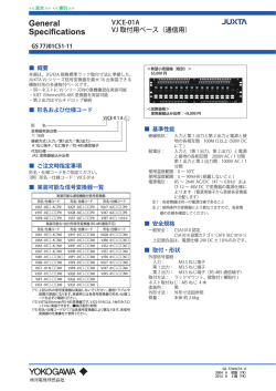
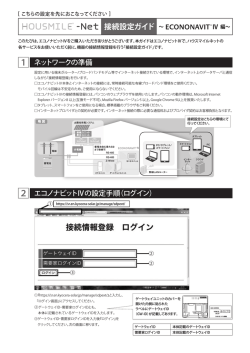
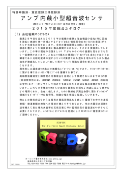
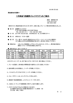
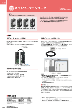
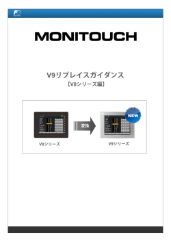
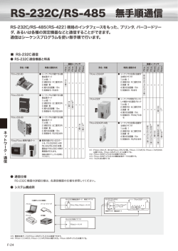
NOTICE
E5AK-T
Digital Controller
INSTRUCTION MANUAL
Thank you for purchasing this
OMRON product.
This manual primarily describes
precautions required installing and
operating the digital controller. Before
operating the product, read this
manual thoroughly to acquire sufficient
knowledge of the product. Keep this
manual for future reference.
OMRON Corporation
9. If you remove the controller from its case, never
touch nor apply shock to the electronic parts
inside.
10. Do not cover the controller.
11. Do not use the controller in the following places:
- Places subject to icing, condensation, dust or
corrosive gas (especially sulfide gas or
ammonia gas)
- Places subject to vibration and large shocks
- Places subject to splashing liquid or oil
atmosphere
- Places subject to intense temperature changes
- Places subject to heat radiation from a furnace.
12. Be sure to wire properly with correct polarity of
terminals.
13. Avoid wiring near high voltage sources and power
lines carrying large currents.
AC100-240V (-15% to +10%), 50/60 Hz,
16VA
AC24V (-15% to +10%), 50/60Hz, 12VA
DC24V (-15% to +10%), 8W
Thermocouple, platinum resistance
thermometer, current input, voltage input
According to output unit
1a AC 250 V, 3A (resistive load)
ON/OFF or PID control
-10 to 55°C (For UL3121-1, IEC/EN61010-1,
Surrounding AirTemperature:50°C)
35 to 85%
-25 to 65°C
Approx. 450 g
Front panel : NEMA4 for indoor use (IP66
equivalent)
Installation category II, Pollution degree 2.
(Conforming to IEC/EN61010-1, UL3121-1, CSA C22.2 No.1010.1)
2000m max.
T2A, AC250V, Time-lag, Low-breaking
capacity
and power
consumption
- Input
- Control output
- Auxiliary output
- Control method
- Ambient temperature
- Ambient humidity
- Storage temperature
- Weight
- Enclosure ratings
- Setup environment
- Altitude
- Recommended fuse
0691369-0B
12
Basic insulation is used between the outputs (Between relay output and analog output)
If reinforced insulation is required between the outputs, connect to a device that does
not have exposed chargeable parts and whose basic insulation is suitable for the
maximum voltage used in the outputs.
M UNPACKING
Make sure that the package contains the
following items. If all the items are not in
the package or an item is damaged,
contact your dealer immediately.
M NAMES OF PARTS ON FRONT PANEL
Program status
indicators
Bar graph
• E5AK-T -------------------------- 1
• Mounting bracket ------------- 2
• Instruction Manual ------------ 1
SV
0
RMT
HOLD
MANU
OUT1
OUT2
RST
SUB1
AT
SUB2
WAIT
%
OUT1 OUT2
SUB1 SUB2
MANU RMT
HOLD RST
WAIT AT
Pattern No.
7 8.8.8.8
PTN TIME
100
Operation status
indicators
RUN/RESET key
No.1 display
PV
8.8.8.8
PTN
• No.1 display: Displays process values or parameter symbol.
• No.2 display: Displays present set point, manipulated variable or
parameter settings.
• Pattern No.: Displays pattern No..
• Program status indicators: Indicate how the present-SP of the
operating step changes.
• Operation status indicators
- OUT1: Lights when the “CONTROL OUTPUT 1” is ON.
- OUT2: Lights when the “CONTROL OUTPUT 2” is ON.
- SUB1: Lights when the “AUXILIARY OUTPUT 1” is ON.
- SUB2: Lights when the “AUXILIARY OUTPUT 2” is ON.
- MANU: Lights in the manual operation mode.
- RST: Lights when the control is in reset status.
- RMT: Lights during remote operation.
- HOLD: Lights when the program is in hold status.
- WAIT: Lights when the program is in wait status.
- AT: Flashes during auto-tuning.
• Bar graph: Displays pattern elapseing time %.
• RUN/RESET key: Switches between run and reset operation.
• Display key: Selects parameters.
• Down key: Each press returns the setting.
• Up key: Each press advances the setting.
No.2 display
RUN
RST
A
M
E5AK
Display key
Down key
Up key
RUN/RST
PRECAUTIONS IN USING THE PRODUCT
When the product is used under the
circumstances or environment
below,ensure adherence to limitations
of the ratings and functions.Also,take
countermesures for safety precautions
such as fail-safe installations.
• Use under circumstances or
environment which are not described
in the instruction manual.
• Use for nuclear power control, railway,
aircraft, vehcle, incinerator, medical
equipment,entertainment
equipment,safety device etc...
• Use for applications where death or
serious property damage is possible
and extensive safety precautions are
required.
PRECAUTIONS ON SAFETY
WARNING
Incorrect handling may cause death or injury.
WARNING
M SETTING THE OUTPUT UNIT
[OUT]
E53-R
E53-S
E53-Q
E53-Q3
E53-Q4
E53-C3
E53-C3D
E53-V34
E53-V35
M EXTERNAL
DIMENSIONS
(unit: mm)
96□
13.5
SDA 32
EV2 19
10
9
8 +
7 −
6 +
OUT2
5
4
3
2
1
SUB1
30 31 32 20
19 OPTION1
29
18
28
17
27
CT
16
26
OPTION3 25
15
14
24
13
RSP + 23
−
12
22
4-20mA
33
11 +
21
COM 18
OPTION2
−
+
−
W
B
SD 20
RDA 19
RD 19
RDB 20
SG 18
SG 18
RS-232C
E5AK-T□B□
O
A
SDB 31
+
Event input1/2
A
B
+
E5AK-T□01□ E5AK-T□02□
COM 24
+
+
−
Event input3/4
E5AK-T□F□
Pt
E5AK-T□03□
EV4 25
−
Transfer output
mA
20
EV3 26
L
29
−
19
+
4-20mA
−
31
● OPTION3
30
V
32
RS-485
RS-422
● OPTION2
C
−
TC
E5AK-T□B□
+
• Do not wire the terminals which are not used.
M CABLE CONNECTIONS
• RS-232C interface: E5AK-TM01M
Host computer
E5AK-T
RS-232C:25P
No.
100
RS-232C
1
FG
2
SD
20 SD
3
RD
19 RD
4
RS
18 SG
5
CS
6
DR
20
ER
7
SG
• Only one controller can be connected to the host computer.
• The cable length should not exceed 15 meters.
• Use shielded twisted pair leads (AWG28 min.) for the cables.
No.
Shielded
cable
PV
8.8.8.8
OUT1
SV
PTN
7 8.8.8.8
PTN TIME
100
OUT2
RMT
HOLD
MANU
OUT1
OUT2
RST
SUB1
AT
SUB2
112
To ensure safe and correct use of this
product, also read the following
manuals:
• E5AK-T Digital Controller
User’s Manual
The above manuals can be obtained
from any OMRON sales office or
dealer.
● OPTION1
EV1 20
AC100-240V
50/60Hz
16VA
SOURCE
or
AC/DC24V
50/60Hz
OUT1
12VA, 8W
SUB2
91□
EN
M WIRING TERMINALS
MAIN SPECIFICATIONS
- Supply voltage
• RS-422 interface: E5AK-TM02M
• RS-485 interface:E5AK-TM03M
WAIT
0
%
Host computer
RUN
RST
E5AK-T(No.0)
E5AK-T(No.30)
RS-422
RS-422
Host computer
RS-485
RS-422
Shielded cable
A<B:"1" Mark
A>B:"0" Space
A
M
Bracket
Shielded cable
E5AK
Press down on the hook on the top of the front panel
(part pointed with an arrow in the above drawing) and
turn a screwdriver to loosen the screw on the lower
part of the front panel.
Watertight packing
Setting is not required on the E5AK-TPRR □□ .
No.
Terminator ×2
(240Ω 1/2W)
No.
−
32 SDA
+
RDA
32 SDA
RDB
31 SDB
31 SDB
SDA
19 RDA
19 RDA
SDB
20 RDB
20 RDB
SG
18
18
SG
FG
SG
FG
M INSTALLATION
• Mounting Panels
• Mounting the Controller
110 min.
Unit (mm)
Terminator(120Ω 1/2W)
E5AK-T(No.0)
E5AK-T(No.30)
RS-485
RS-485
No.
No.
32
A
32
31
B
31
A
B
19
A
19
A
20
B
20
B
Do not touch the terminals while the power is ON.
This may cause an electric shock.
NOTICE
Items shown below are necessary for
safe usage.
Please note them carefully.
1. Do not use the product in place
where explosive or flammable gases
may be present.
2. Never disassemble , repair or modify
the product.
3. Tighten the terminal screws properly.
4. Use the specified size solderless
terminals for wiring.
5. Use the product within the rated
supply voltage.
6. Use the product within the rated load.
7. The life expectancy of the output
relay varies considerably according
to its the output relay within its rated
load and electrical life expectancy, if
the output relay is used beyond its
life expectancy, its contacts may
become fused or burned.
8. A switch or circuit breaker should be
provided close to this unit.
The switch or circuit breaker should
be within easy reach of the operator,
and must be marked as a
disconnecting means for this unit.
120 min.
• Up to 32 controllers including a host computer can be connected .
• The total cable length should not exceed 500 meters. Use shielded twisted pair leads (AWG28 min.) for the cables.
• Attach terminators to the controllers at both ends of a series of controllers connected in an open configuration. For example, in the configuration on the left, connect terminators to the
host computer and the unit No.30, and do not connect terminators to connector Nos. 0 to 29.
+0.8
92 0
M ERROR DISPLAY
+0.8
92 0
Recommended panel thickness is 1 to 8 mm.
North America
OMRON ELECTRONICS LLC
Phone:1-847-843-7900
OMRON CANADA INC.
Phone: 1-416-286-6465
Phone : 1-514-636-6676
(French Language)
Europe
OMRON EUROPE B.V.
(EUROPEAN H.Q.)
Phone: 31-23-56-81-300
Fax : 31-23-56-81-388
(1) Attach the watertight packing from the terminal side and then insert
the controller to the panel.
(2) Fit the mounting bracket (supplied) into the grooves on the top and
bottom sides of the rear case.
(3) Alternately tighten the top and bottom screws on the mounting bracket
applying equal pressure a little at a time until the rachet rotates freely.
Asia / Pacific
欧姆龍(中国)有限公司 (中国)
Phone: (8610)8391-3005
歐姆龍亞洲有限公司 (香港)
Phone: 852-2375-3827
台灣歐姆龍股有限公司總公司(台灣)
Phone: 886-2-2715-3331
韓国OMRON株式会社(大韓民国)
Phone: 82-2-512-0871(Korean)
Phone: 82-2-549-2766
(English/Japanese)
OMRON ASIA-PACIFIC PTE LTD.
(Singapore)
Phone: 65-6835-3011
OMRON ELECTRONICS PTY.LTD.
(AUSTRALIA)
Phone: 02-9878-6377
M Others
Input error
Input is in error.
Check the input wiring (incorrect,
disconnected, or short-circuited),
input type .
Memory error
Internal memory is in error.
Repair.
A/D converter error
Internal circuits are in error.
Repair.
Calibration data error
The calibration data is in error. This
message is displayed for two seconds
when the power is turned ON.
Repair.
Display range
over
This is not an error. This is displayed
when the display range is exceeded.
• Only the E53-R output unit can be used for
E5AK-TPRR □□ controllers.
• No user serviceable parts.
However, Output unit can be replaced.
Return to OMRON for all repairs.
JPN
取扱説明書
オムロン製品をお買い上げいただきあり
がとうございます。
この製品を安全に正しく使用していただ
くために、お使いになる前にこの取扱説
明書をお読みになり、十分にご理解くだ
さい。
お読みになった後は、いつも手元に置い
てご使用ください。
この商品を安全に正しく使用していただ
くために次のマニュアルを併せてご覧く
ださい。
・形 E5AK-T デジタル調節計
ユーザーズマニュアル(SCEE-703)
なお上記マニュアルは、当社営業所また
は販売店にご請求ください。
■箱の中身
1. ドローアウトしたときは、
絶対に電子部品に手を触れたり衝撃
を与えたりしないでください。
2. 形 E5AK-T の周囲をふさがないでください。
3. 次の環境での使用を避けてください。
・氷結、結露、塵あい、
腐食性ガス
(とくに硫化ガス、
アンモニア
ガスなど)
のあるところ
・振動、衝撃の影響が大きいところ
・冠水、被油のあるところ
・温度変化が激しいところ
・炉の放熱を受けるところ
4. 端子の極性を確認して、正しく配線してください。
5. 高圧、強電流線と接近しないように配線してください。
・形 E5AK-T 本体 -----------------・取付金具 -------------------------・取扱説明書 -----------------------
1
2
1
ご使用に際してのお願い
次に示す条件や環境で使用する場合は、
定格、機能に対して余裕を持った使い方
やフェールセイフなどの安全対策へのご
配慮をいただくとともに、当社営業担当
者までご相談くださるようお願いいたし
ます。
●取扱説明書に記載のない条件や環境で
の使用
●原子力制御・鉄道・航空・車両・燃焼
装置・医療機器・娯楽機械・安全機器
などへの使用
●人命や財産に大きな影響が予測され、
特に安全性が要求される用途への使用
安全上のご注意
■フロントパネルの名称と働き
プログラム状態
表示LED
第1表示
PV
8.8.8.8
7 8.8.8.8
PTN TIME
100
0
パターンNo.
SV
PTN
バーグラフ
RMT
HOLD
MANU
OUT1
OUT2
RST
SUB1
AT
SUB2
第2表示
WAIT
%
OUT1 OUT2
SUB1 SUB2
MANU RMT
HOLD RST
WAIT AT
●パターン No.:パターン No. を表示します。
●プログラム状態表示LED:現在ステップの現在目標値の変化方向を
表示します。
●動作表示 LED
・OUT1:
「制御出力1」が ON のとき点灯します。
・OUT2:
「制御出力2」が ON のとき点灯します。
・SUB1:「補助出力1」が ON のとき点灯します。
・SUB2:「補助出力2」が ON のとき点灯します。
・MANU:マニュアル動作のとき点灯します。
・RST:運転停止(リセット状態)のとき点灯します。
・RMT:リモート動作中に点灯します。
・HOLD:プログラムのホールド中に点灯します。
・WAIT:プログラムのウェイト中に点灯します。
・AT:AT(オートチューニング)中に点滅します。
●バーグラフ:パターン経過時間割合を表示します。
●ラン/リセットキー:ラン動作とリセット動作を切り替えます。
●モードキー:パラメータを切り替えます。
●ダウンキー:押すごとに設定値または内容を戻します。
●アップキー:押すごとに設定値または内容を進めます。
RUN
RST
A
M
E5AK
ラン/リセットキー モードキー
ダウンキー
アップキー
RUN/RST
●第1表示:現在値またはパラメータ記号を表示します。
●第2表示:現在目標値、操作量、またはパラメータの設定値(設定
内容)を表示します。
■出力ユニットのセッティング
[OUT]
E53-R
E53-S
E53-Q
E53-Q3
E53-Q4
E53-C3
E53-C3D
E53-V34
E53-V35
■外形寸法図(単位:mm)
96□
13.5
100
8.8.8.8
OUT1
お願い
以下に示す項目は、安全を確保するため
に必ず守ってください。
1. 引火性、爆発性ガスの環境では使用し
ないでください。
2. この製品を分解したり、修理、改造し
ないでください。
3. 端子台のねじは確実に締めてくださ
い。
4. 配線用圧着端子は、指定サイズのもの
を使用してください。
5. 電源電圧は、仕様範囲内で使用してく
ださい。
6. 負荷は定格以下で使用してください。
7. 出力リレーの寿命は、開閉容量・開閉
条件により大きく異なるので、定格負
荷・電気的寿命回数内で使用してくだ
さい。寿命を超えた状態で使用すると
接点溶着や焼損の恐れがあります。
8. 作業者がすぐ電源をOFFできるようス
イッチまたはサーキットブレーカを設
置し、適切に表示してください。
7 8.8.8.8
OUT2
RMT
HOLD
MANU
OUT1
OUT2
RST
SUB1
AT
SUB2
WAIT
5
4
3
2
1
SUB1
−
30 31 32 20
19 OPTION1
29
18
28
17
27
CT
16
26
OPTION3 25
15
14
24
13
RSP + 23
−
12
22
4-20mA
33
11 +
21
OPTION2
イベント入力1/2
形E5AK-T□B□
TC
RDA 19
RD 19
RDB 20
SG 18
SG 18
RS-232C
32
B
SD 20
31
A
19
B
20
RS-485
RS-422
形E5AK-T□01□ 形E5AK-T□02□ 形E5AK-T□03□
O
W
● OPTION3
● OPTION2
C
30
+
+
V
EV3 26
L
4-20mA
EV4 25
29
−
−
伝送出力
−
mA
−
COM 24
+
−
イベント入力3/4
形E5AK-T□F□
Pt
+
形E5AK-T□B□
+
・機種によって使用しない端子および空き端子には配線しないでください。
■ケーブル接続
● RS-232C インタフェース:形 E5AK-T □ 01 □
上位コンピュータ
形E5AK-T
RS-232C:25P
No.
RS-232C
1
FG
2
SD
20 SD
3
RD
19 RD
4
RS
18 SG
5
CS
6
DR
20
ER
7
SG
・接続形態は、1:1です。
・ケーブル長は、最大15mです。線路長を延長する場合は、当社RS-232C光インタフェー
ス(形 Z3RN)をご使用ください。
・ケーブルには、シールド付ツイストペア線(AWG28 以上)をご使用ください。
No.
シールド
線
形E5AK-T(No.0)
A
止め金具
E5AK
防水パッキン
ドローアウト時は、フロントパネル上面のフッ
● RS-485 インタフェース:形 E5AK-T □ 03 □
形E5AK-T(No.30)
RS-422
シールド線
RUN
RST
ク(上図の矢印部)を押しながら、前面下部の
ネジをドライバでゆるめて下さい。
上位コンピュータ
RS-422
0
%
No.
上位コンピュータ
RS-485
RS-422
ターミネータ×2
(240Ω 1/2W)
No.
−
32 SDA
+
RDA
32 SDA
RDB
31 SDB
31 SDB
SDA
19 RDA
19 RDA
SDB
20 RDB
20 RDB
SG
18
18
SG
シールド線
FG
A<B:「1」マーク
A>B:「0」スペース
ターミネータ
(120Ω 1/2W)
形E5AK-T(No.0)
SG
FG
形 E5AK-TPRR □□は、セッティング不要です。
■取り付け
形E5AK-T(No.30)
RS-485
RS-485
No.
No.
32
A
32
31
B
31
B
19
A
19
A
20
B
20
B
A
●取り付け方
●取り付けパネル加工図
110以上
単位(mm)
・接続形態は、1:1または1:Nです。1:N接続時は上位コンピュータを含め最大 32 台まで接続できます。
・ケーブル長は、合計で最大 500m です。ケーブルには、シールド付ツイストペア線(AWG28 以上)をご使用ください。
・伝送路の両端の装置のみ、エンド局指定(ターミネータを接続する)してください。たとえば、上の例で、上位コンピュー
タと No.30 のユニットにターミネータを接続して、No. 0∼ 29 のユニットはターミネータなしにしてください。
120以上
92
+0.8
0
92 +0.8
0
取り付けパネル厚は 1∼8mm です。
(1)本体に端子側から防水パッキンを取り付けてから、パネルに挿入し
てください。
(2)付属の取付金具をリアケースの上面および下面の固定溝にはめ込ん
でください。
(3)上下の取付金具のねじを、交互に少しずつバランスをとりながら、ラ
チェットが空回りするところまで締め付けてください。
オムロン株式会社
営業統轄事業部
東京都品川区大崎1-11-1ゲートシティ大崎ウエストタワー14F(〒141-0032)
● FAXによるお問い合わせ
● 技術的なお問い合わせ 0120-919-066(フリーコール)
携帯電話・PHSなどは 055-982-5015です。
カスタマサービスセンタ お客様相談室 FAX 055-982-5051
● インターネットによるお問い合わせ
直通の制御機器の技術窓口は055-982-5000です
■営業時間:9:00∼12:00/13:00∼19:00(土・日・祝祭日は17:00まで)
■営 業 日:年末年始を除く
OUT2
−
COM 18
A
SDB 31
+
EV2 19
10
9
8 +
7 −
6 +
SDA 32
+
EV1 20
● RS-422 インタフェース:形 E5AK-T □ 02 □
SV
PTN
PTN TIME
100
誤った取り扱いをすると、死亡または
重傷を負う可能性が想定される場合を
示します。
警告
通電中は端子には触らない
でください。
感電の恐れがあります。
AC100-240V
50/60Hz
16VA
または SOURCE
AC/DC24V
50/60Hz
OUT1
12VA, 8W
● OPTION1
PV
M
警告
出力相互間は基礎絶縁です。(リレー出力、アナログ出力間)出力相互間で
強化絶縁が必要な場合は露出した充電部を持たない装置でかつ、それぞれの
出力の最高使用電圧に適した基礎絶縁がされている装置へ接続ください。
SUB2
動作表示LED
次のものが箱に入っているかどうかお確
かめください。もし足りなかったり破損
していたりした場合は、すぐにお買い求
めの販売店にご連絡ください。
AC100-240V(-15% ∼ +10%)
50/60Hz, 16VA
AC24V (-15% ∼ +10%) 50/60Hz, 12VA
DC24V (-15% ∼ +10%) 8W 熱電対、白金測温抵抗体
電流入力、電圧入力
制御出力 機種による
補助出力 1a AC250V 3A(抵抗負荷)
制御方式 ON/OFF または 2 自由度 PID
使用周囲温度 -10 ∼ 55℃(UL3121-1, IEC/EN61010-1 に従
う周囲温度:50℃)
使用周囲湿度 35 ∼ 85%
保存温度 -25 ∼ 65℃
質量 約 450 g
保護構造 前面:NEMA4 屋内用(IP66 相当)
設置環境 設置カテゴリII、汚染度2
(IEC/EN61010-1, UL3121-1, CSA C22.2 No.1010.1による)
高度 2000m 以下
推奨ヒューズ T2A, AC250V タイムラグ 低遮断容量
112
デジタル調節計
電源電圧 および
消費電力
入力 91□
形 E5AK-T
■端子部の使い方
主な仕様
正しい使い方
http://www.fa.omron.co.jp/support/
■エラー表示
■ その他
s.err
入力異常
入力に異常があります。
入力の誤配線、断線、短絡および入力種
別を確認してください。
e111
メモリ異常
内部メモリに異常があります。
修理が必要です。
e333
A/Dコンバータ異常
内部回路に異常があります。
a.err
校正データ異常
校正データに異常があります。
電源投入時2秒間表示されます。
[[[[
]]]]
表示範囲オーバー
エラーではありませんが、表示範囲を超え
たときに表示されます。
・形 E5AK-TPRR □□の出力ユニット
・お客様で交換できる部品はありませ
には、形 E53-R のみ使用できます。
ん。ただし、出力ユニットは交換で
修理が必要です。
修理が必要です。
きます。
修理の際は製造元にご返却ください。
© Copyright 2026 Paperzz