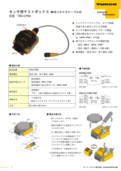
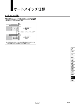
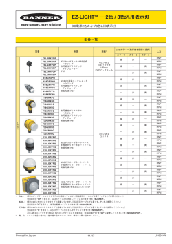
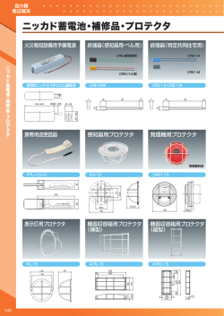
リモートシステム
ユーザーズガイド
配線図
システム構成
■RS12T-422-PU
[ 検出部 ]
リモートセンサシステム
スイッチ信号仕様 /12 点伝送コンパクト形状
[ 伝送部 ]
電力供給
(12V DC/230mA)
出力部:RS12E-422N-PU(NPN 仕様 )
RS12E-422P-PU(PNP 仕様 )
伝送部:RS12T-422-PU
直流 3 線式
センサ
[ 出力部 ]
24V DC
電力供給
RS12T
外部電源
(24V DC)
RS12E
外部
制御機器
max.12 点
検出信号
* Please turn over for English guide.
検出信号
信号伝送
ご 使 用 に 際 し て は、 取 扱 説 明 書 を よ く お 読 み に な り、 安 全 に 対 し て
十分に注意を払い、正しくお取り扱いください。
◆本 製 品 に 関 す る 設 置・ 保 守・ 故 障 等 の 処 置 は、 必 ず 電 源 を 切 っ て
から行ってください。
◆電 源は必ず、スイッチング電源等の定電圧電源をご使用ください。
( 全 波 整 流 電 源 な ど、 定 格 以 上 の リ ッ プ ル が 存 在 す る 電 源 を 使 用
しますと、誤動作の原因になります。)
SW 1
(NPN)
SW 2
(NPN)
SW 3
(NPN)
SW 4
(NPN)
SW 5
(NPN)
SW 6
(NPN)
【各部の役割】
設置に際してのご注意
(ご使用の前に必ずお読みください。)
■RS12E-422N-PU(NPN 仕様)
センサ
検出部:市販の検出スイッチを接続して「検出信号」を「伝送部」に送ります。
伝送部:「検出部」に電源を供給すると共に、「検出部」からの検出信号を
非接触で「出力部」に伝送します。
出力部:「伝送部」から伝送された検出信号を外部に出力すると共に、「検出部」
「伝送部」に必要な動作電源を供給します。
SW 7
(NPN)
SW 8
(NPN)
SW 9
(DC2W)
SW 10
(DC2W)
SW 11
(DC2W)
SW 12
(DC2W)
◆各 ユ ニ ッ ト 間 の 配 線 は、 配 線 図 を 参 考 に し て、 正 し く 結 線 し て
RS12T
(+)
(-)
(SO)
(+)
(-)
(SO)
(+)
(-)
(SO)
(+)
(-)
(SO)
(+)
(-)
(SO)
(+)
(-)
(SO)
(+)
(-)
(SO)
(+)
(-)
(SO)
(+)
RS12E
黒(POL)
白(+)
空(-)
茶(SI1)
RS12T
白(+)
24V DC
赤(SI2)
内
内
空(-)
SW 1
(PNP)
黒(INZONE)
SW 2
(PNP)
部
赤(SO2)
部
SW 4
(PNP)
橙(SO3)
回
回
路
路
SW 5
(PNP)
黄(SO4)
緑(SI5)
緑(SO5)
SW 6
(PNP)
青(SI6)
青(SO6)
紫(SI7)
SW 7
(PNP)
紫(SO7)
灰(SI8)
茶*(SI9)
(-)
(+)
灰(SO8)
SW 8
(PNP)
茶*(SO9)
SW 9
(DC2W)
赤*(SO10)
橙*(SO11)
SW 10
(DC2W)
黄*(SO12)
SW 11
(DC2W)
赤*(SI10)
(-)
(+)
橙*(SI11)
(-)
(+)
SW 12
(DC2W)
黄*(SI12)
(-)
RS12E
黒(POL)
白(+)
空(-)
茶(SI1)
(+)
(-)
(SO)
(+)
(-)
(SO)
(+)
(-)
(SO)
(+)
(-)
(SO)
(+)
(-)
(SO)
(+)
(-)
(SO)
(+)
(-)
(SO)
(+)
(-)
(SO)
(+)
SW 3
(PNP)
茶(SO1)
橙(SI3)
黄(SI4)
■RS12E-422P-PU(PNP 仕様)
センサ
PLC側
白(+)
24V DC
空(-)
黒(INZONE)
赤(SI2)
内
内
部
部
回
回
路
路
茶(SO1)
橙(SI3)
赤(SO2)
黄(SI4)
橙(SO3)
黄(SO4)
緑(SI5)
緑(SO5)
青(SI6)
青(SO6)
紫(SI7)
紫(SO7)
灰(SO8)
灰(SI8)
茶*(SO9)
(-)
(+)
茶*(SI9)
(-)
(+)
赤*(SI10)
(-)
(+)
橙*(SI11)
(-)
黄*(SI12)
赤*(SO10)
橙*(SO11)
黄*(SO12)
■上図の SW9 ~ 12 は直流 2 線式センサの配線例です(抵抗は1~ 2 KΩ程度を配線して下さい)。直流3線式センサもご使用いただけます。
ください。
■ RS12E 及び RS12T の緑 *、青 *、紫 * のケーブルは未使用です。
◆誘 導ノイズなどによる誤動作を避けるため、ケーブルは動力線や
高圧機器から離して、配線してください。
設置条件
ケーブル曲げ半径について
周囲金属による影響及び、製品間の相互干渉を避けるため、
必ず下表に示す値以上の空間を開けて設置してください。
外形寸法図
伝送部:RS12T-422-PU
■RS12T-422-PU
PLC側
型式
RS12T-422-PU
RS12E-422N-PU、RS12E-422P-PU
出力部:RS12E-422N-PU , RS12E-422P-PU
A*
B
C
30
23
250
■周囲金属
ケーブルを屈曲し
て配線する場合は、
50mm 以上の曲げ
半径を確保して下
さい。
■並列設置
A
(mm)
C
50mm
B
*取付の際は、ケーブルを過大な力で引っ張らない
で下さい。
* 1面のみ、金属に接する事が可能です。
LED の表示内容について
■ステータスLED(緑)
点灯状態 点滅周期 パターン
点灯
-
-
消灯
-
-
消灯が長い
点滅
遅い
(1.5 秒) 点灯が長い
点滅
消灯が長い
点滅
中速
(0.6 秒) 点灯が長い
点滅
高速
同じ間隔で
点滅
(0.2 秒)
点滅
仕様
型式
対応センサ
ドライブ電圧
ドライブ電流
入力信号点数
伝送距離
許容軸ズレ
使用周囲温度
保護構造
接続ケーブル
材質
重量
型式 NPN 出力
PNP 出力
電源電圧
消費電流
出力信号点数
負荷電流
LED 表示
回路保護
使用周囲温度
保護構造
接続ケーブル
材質
重量
RS12E-422N-PU
RS12E-422P-PU
24V DC ± 10%(リップル含む)
≦ 600mA
12 点 +1 点(ステータス)
≦ 50mA/1 出力
ステータス(緑)、出力(橙)
短絡保護、高温保護、
逆接保護、サージ保護
0...+50℃
IP67
PUR φ 8.6
2x0.5mm2+13x0.18mm2
ABS
本体 80 g + ケーブル 105g/m
電源電圧
消費電流の合計
残留電圧
負荷電流
mm
8
Y
7
6
5
3
定格動作範囲
2
1
8
6
4
2
X:軸ズレ (mm)
Y:伝送距離 (mm)
X
4
・ドライブ電流値を超える場合は、接続するセンサの数を減らしてください。
No.T313A01C
動作するセンサをご使
用下さい。
RS12T-422-PU / RS12E-422N-PU , RS12E-422P-PU
・検出部として複数のセンサを使用する場合は、各センサの消費電流の合計値がドライブ電流以下になることを
必ず確認してください。
2014. 04.18
左表の条件内で正しく
12V DC
≦ 230mA
≦ 3.5V
---
伝送領域図(代表例:電源電圧 24V 時/金属非埋め込み)
Y
0
2
点灯が長いパターン
ON
OFF
消灯が長いパターン
ON
OFF
短絡保護が作動しています。
点滅周期
■信号LED(橙)
使用可能なセンサ
RS12T-422-PU
直流3線式センサ
12V ± 1.5V DC
≦ 230mA
12 点
2...5mm
± 3mm
0...+50℃
IP67
PUR φ 8.6
2x0.5mm2+13x0.18mm2
ABS
本体 75g
+ ケーブル 105g/m
内容
電源が正しく供給されている。
電源が供給されていない。
温度異常時。
発振回路で過電流。
使用電圧が高い。
使用電圧が低い。
4
6
X
8
ドライブ電流 ≦ 230mA
インゾーン LED は RS12E/RS12T が対向状態であり、通信可能である場合、点灯します。
また、各センサからの信号が出力されると、それに応じて点滅します。
出力 1 フレーム
ON 点滅 0.6 秒
OFF 点滅 0.3 秒
信号
1
2
3
4
5
6
7
8
9
10
11
12
2 フレーム
点滅 0.3 秒
点滅 0.8 秒
点灯 0.3 秒
3 フレーム
0.3 秒
点滅
0.6 秒
0.3 秒
点灯
0.6 秒
0.3 秒
点滅
0.6 秒
0.3 秒
点灯
0.6 秒
0.3 秒
点滅
0.6 秒
0.3 秒
点灯
0.6 秒
1 フレーム
・例 1
SI10 が OFF
ON
OFF
・例 2
SI4 が ON
ON
OFF
・例 3
SI7 が ON
ON
OFF
2 フレーム
消灯 0.5 秒
固定
3 フレーム
消灯 0.5 秒
固定
消灯 0.8 秒
固定
(旧:日本バルーフ株式会社)
技術サービス : TEL 0493-65-1688 FAX 0493-65-3171
受付時間:月~金(祝・祭日を除く)
9:00 ~ 12:00 13:00 ~ 17:00
http://www.b-plus-kk.jp/
E-mail [email protected]
Power supply
( 12V DC / 230mA )
Output sensor : RS12E-422N-PU (NPN)
RS12E-422P-PU (PNP)
DC 3-wire
sensor
Transmitter : RS12T-422-PU
24V DC
Power
supply
RS12T
External Power
Unit(24V DC )
Attention for Installation
(Read this section thoroughly before installation.)
(+)
(-)
(SO)
(+)
(-)
(SO)
(+)
(-)
(SO)
(+)
(-)
(SO)
(+)
(-)
(SO)
(+)
(-)
(SO)
(+)
(-)
(SO)
(+)
(-)
(SO)
(+)
SW 2
(NPN)
RS12E
Signal
transmission
Detected
signal
RS12T
SW 1
(NPN)
Host device
SW 3
(NPN)
max.12 signals
*Please turn over for Japanese guide.
■RS12E-422N-PU(NPN)
Sensor
SW 4
(NPN)
Detected
signal
SW 5
(NPN)
【Function of each component】
SW 6
(NPN)
Before using the Remote Sensor, read this manual carefully.
During installation and operation, pay close attention to the safety aspect.
Detector :
◆ Ensure the power is switched off during installation or
maintenance operations.
Transmitter :
◆ Use a regulated power supply, e.g. switch-model type.
Simpler power supplies, such as a full-wave rectification type,
will cause the permissible ripple rating to be exceed and may
cause malfunction.
Output Sensor :Puts out detected signal to external controller, also
sends power for operating of Detector and Transmitter. Connects Detector sensor (max.12) and transmits
the detected signals to Transmitter.
SW 7
(NPN)
SW 8
(NPN)
Provides power for Detector, also passes detected
signals from Detector to Output Sensor.
SW 9
(DC2W)
SW 10
(DC2W)
SW 11
(DC2W)
SW 12
(DC2W)
RS12E
BK(POL)
WH(+)
Pale BU(-)
BN(SI1)
■RS12T-422-PU
PLC side
WH(+)
Pale
BU(-)
24V DC
SW 1
(PNP)
SW 2
(PNP)
BK(INZONE)
RD(SI2)
SW 3
(PNP)
BN(SO1)
OG(SI3)
RD(SO2)
YE(SI4)
GN(SI5)
BU(SI6)
SW 5
(PNP)
YE(SO4)
GN(SO5)
SW 6
(PNP)
BU(SO6)
SW 7
(PNP)
VT(SO7)
GY(SI8)
BN*(SI9)
(-)
(+)
SW 4
(PNP)
OG(SO3)
VT(SI7)
GY(SO8)
SW 8
(PNP)
BN*(SO9)
SW 9
(DC2W)
RD*(SO10)
RD*(SI10)
(-)
(+)
OG*(SI11)
(-)
(+)
■RS12E-422P-PU(PNP)
Sensor
OG*(SO11)
SW 10
(DC2W)
YE*(SO12)
SW 11
(DC2W)
YE*(SI12)
SW 12
(DC2W)
(-)
RS12T
(+)
(-)
(SO)
(+)
(-)
(SO)
(+)
(-)
(SO)
(+)
(-)
(SO)
(+)
(-)
(SO)
(+)
(-)
(SO)
(+)
(-)
(SO)
(+)
(-)
(SO)
(+)
RS12E
PLC side
BK(POL)
WH(+)
Pale BU(-)
BN(SI1)
WH(+)
Pale
BU(-)
24V DC
BK(INZONE)
RD(SI2)
BN(SO1)
OG(SI3)
RD(SO2)
YE(SI4)
GN(SI5)
BU(SI6)
OG(SO3)
Internal circuit
12 signal transmission / Compact shape
■RS12T-422-PU
[ Output sensor ]
Internal circuit
[ Transmitter ]
[ Detector ]
Remote sensor sysytem
Wiring diagram
Internal circuit
System configuration
Internal circuit
Remote System
User’s Guide
YE(SO4)
GN(SO5)
BU(SO6)
VT(SI7)
VT(SO7)
GY(SO8)
GY(SI8)
BN*(SO9)
(-)
(+)
BN*(SI9)
(-)
(+)
RD*(SI10)
(-)
(+)
OG*(SI11)
(-)
YE*(SI12)
RD*(SO10)
OG*(SO11)
YE*(SO12)
◆ Ensure correct connections by reference to the wiring dia
gram.
■ SW9...12 of the wiring diagram is an example of the DC-2 Wire sensor wiring(Recomend resistance is 1...2K ohm).DC-3 wire Sensor can also be used.
◆ To avoid malfunction caused by induction noise, cable
should be kept apart from motor or other power cable.
Installation notes
■ Cable GN* and BU* and VT* of RS12E/RS12T is not used.
Dimension
Transmitter:RS12T-422-PU
Bending radius of Cable
In order to avoid influence of surrounding metal, or to
avoid mutual influence between parallel-mounted sensors, keep the minimum free zone as described below.
Output sensor:RS12E-422N-PU
Type code
RS12T-422-PU
RS12E-422N-PU、RS12E-422P-PU
A*
B
C
30
23
250
* The sensing surface cannot have contact with a metal.
■ Surrounding metal
A
The minimum
■ Parallel installation bending
radius for
thesensors
are 50mm.
50mm
C
B
(mm)
* Never pull the cable strongin installing
LED indication
■ Status LED(Green)
LED
ON
OFF
Blink
Blink
Blink
Blink
Blink
Specification of the System
Type code PNP RS12T-422-PU
Applicable sensor
DC 3-wire sensor
Drive voltage
12V ± 1.5V DC
Drive current
≦ 230mA
No. of Input signals
12 signals
Operating distance
2...5mm
Center offset
± 3mm
Applicable sensor
NPN output RS12E-422N-PU
PNP output RS12E-422P-PU
Supply voltage
24V DC ± 10%(including ripple)
Type
code
Current consumption ≦ 600mA
No. of Output signals 12 + 1 (Status )
Load current
≦ 50mA/1 output
LED indication
Status(Green) , Signal(Orange)
Short circuit protection ,
High temperature protection ,
Converse protection ,
Surge suppression
Operating temperature 0...+50℃
Protection class
Cable
IP67
PUR φ 8.6
2x0.5mm2+13x0.18
mm 2
Material
ABS
Weight
75 g+105g/m(cable)
Total current consumption of detectors
must not exceed the rated drive current.
Reduce the switches when the total current consumption exceeds the drive current.
2014. 04.18
No.T313A01C
Circuit protection
Operating temperature
0...+50℃
Protection class
Material
IP67
PUR φ 8.6
2x0.5mm2+13x0.18 mm 2
ABS
Weight
80g + 105g/m(cable)
Cable
Please sure to use
applicable detector
switch according to
the specification on
left.
12V DC
Total current consumption* ≦ 230mA
Residual voltage
≦ 3.5V
Load current
--Supply voltage
*Total consumption current of connected
sensors.
Typical Transmitting Diagram (Supply voltage at 24V /non-flush mount)
RS12T-422-PU / RS12E-422N-PU , RS12E-422P-PU
Y
mm
8
Y
7
X
6
5
X:Center offset(mm)
Y:Operating distance(mm)
4
3
Operating area
2
1
8
6
4
2
0
2
4
6
X
8
Drive current ≦ 230mA
Blinking
Pattern
Lighting time of the
LED is long
Meaning
-
-
The power supply is supplied.
-
-
The power supply is not supplied.
ON
OFF
Off time of the LED is long Anomalous temperature
Slow
(1.5 sec) Lighting time of the LED is long Oscillation circuit overcurrent.
OFF time of the
LED is long
Mid.Speed Off time of the LED is long Supply voltage is high.
(0.6 sec) Lighting time of the LED is long Supply voltage is low.
High speed
The LED flashes at the
Short circuit protection.
(0.2 sec)
same interval
ON
OFF
Blink cycle
■ Signal LED (Orange)
RS12E and RS12T are opposed, LED is lit when you can communicate.
When the output signal from each sensor and flash accordingly.
Output 1st frame
Blinking
ON
0.6 sec.
Blinking OFF
0.3 sec.
Signal
1
2
3
4
5
6
7
8
9
10
11
12
2nd frame
Blinking
0.3 sec.
Blinking
0.8 sec.
Lighting
0.3 sec.
3rd frame
0.3
Blink
0.6
0.3
ON
0.6
0.3
Blink
0.6
0.3
ON
0.6
0.3
Blink
0.6
0.3
ON
0.6
1st frame
sec
sec
sec
sec
sec
sec
sec
sec
sec
sec
sec
sec
2nd frame
3rd frame
(EX.1)
ON
SI10 was OFF.
OFF
(EX.2)
ON
SI4 was ON.
OFF
(EX.3)
ON
SI7 was ON.
OFF
OFF 0.5 sec
Fixed
OFF 0.5 sec
Fixed
(Former NIHON BALLUFF co., Ltd.)
http://www.b-plus-kk.jp/
E-mail [email protected]
OFF 0.8 sec
Fixed
© Copyright 2026 Paperzz