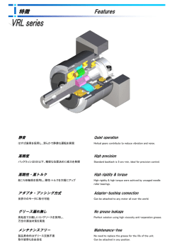
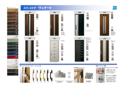
CAT. No. MT010
トルクリミッタ Torque limiter
OTLV-
トルクリミッタはスリッピングクラッチとも呼ばれ、主にプリンタ- ・ 複写機など OA機器の紙送り部に使用される機械要素です。
トルクリミッタOTLV型は、内輪の外周面にコイルスプリングを圧入し、両部品の摩擦力を利用して、トルク入力側(駆動側)から
出力側(従動側)に伝達するトルクを制限する構造となっております。
Torque limiter which is known as spring clutch functions that the shaft connected rotates when a certain torque is applied
to the shaft.
This mechanical component is widely accepted in office automation machines such as printers and copiers,
especially in the paper feeding mechanisms.
Origin Torque limiter utilizes friction force between the inner ring and coil spring fitted around it to generate torque.
This construction assists in limiting the transmitted torque from the input side (driving side) to the output side (driven side).
-1-
■ 特 長 (Features)
1. 正逆両方向の回転に使用可能 (Slips in both rotating directions)
正逆両方向(時計方向・反時計方向)の使用が可能です。
2. 小型 ・ 軽量 (Compact size and light weight)
OTLV-6Bの場合、外径φ18 質量 7.1gw と 当社OTLC-6B と比較し、重量 18% 減
In the case of OTLV-6B, the outer diameter is 18mm and the weight is 7.1g, which is 18% reduction from
the previous model of OTLC-6B.
3. 環境条件(温度・湿度)に影響されにくい ( Used under the wide range of environmental conditions.)
使用環境 : 0℃ ~ 60℃ 90%RH
Operation condition : 0℃ to +60℃, 90%RH
4. 取り付けが容易 (Easy mounting)
回り止めとして、弊社推奨の平行ピン または 専用スプリングピンをご使用下さい。
平行ピンご使用の場合は、軸(シャフト)への圧入は不要です。(すきまばめで可) 内輪スリワリ部がピンの脱落を防止します。
The parallel pin or the spring pin can be used in a shaft to connect to the torque limiter.
Be sure to use the pins recommended by Origin.
In the case of using the pin, it is not necessary for the shaft to be press fitting to the inner ring section
allowing clearance fitting.
A slot in the inner ring prevents the pin coming off from the shaft.
■ 標準仕様 (Specifications for the Standard Models)
トルクリミッタ名称と補助記号 (Naming and auxiliary symbols)
OTLV 総称
内 径
Bore
OTLV
呼びトルク値
Nominal torque
6-
500
B
OTLV =
・6 = 内径 φ6
例 (Example)
トルクリミッタ OTLV型
・500 = 500 gf・cm
Bore φ6
Torque limiter OTLV type ・8 = 内径 φ8
タイプ表示
Type
Bore φ8
形状 ・ 寸法を表すタイプ表示
Indicates a type of Torque limiter.
(49.0 mN・m)
・4000 = 4000 gf・cm
・B = Bタイプ (B type)
・C = Cタイプ (C type)
(392 mN・m)
寸法一覧 (Dimensions)
+0.10
t
2.1-0.08
D1
d1
d2
D2
1000B
6-
d
3
刻印 呼び番号
Marking nominal number
W2
0
-0.2
2.5
W1
主 要 寸 法 (Dimension)
内 径
外 径
幅
Bore
Outside dia
Width
スリワリ位置 シ-ルド内径
Slot position
許容回転数
Outside dia
Width
rotation speed
0
(rpm.)
Bore
Allowable
Shield
呼び番号
d1 +0.10
Nominal Number
Bore of
ジョイント 部 (Joint prat)
外 径
幅
内 径
D1 ±0.4
W1
W2
+0.02
d3 +0.20
0
d2 +0.20
0
D2 0
-0.2
t -0.1
OTLV6-□□□□B
6
18
12
8
8.4
8.2
15
2.5
400
OTLV8-□□□□B
8
20
12
8
10.4
8.2
15
2.5
400
OTLV6-□□□□C
6
20
15.5
11.5
8.4
8.2
17
4
50
OTLV8-□□□□C
8
22
15.5
11.5
10.4
8.2
17
4
50
注)
・□□□□内の数値は、トルクリミッタの呼びトルク値 (gf・cm 表示) です。
・呼びトルク値が 88.2mN・m (900gf・cm)以下の場合は、□内が3桁表示となります。
Note)
The four squares shown above indicate a nominal torque value for the torque limiter in the unit of gf・cm.
Three digits may be possible when a nominal torque value is 88.2mN・m(900gf・cm) or less.
-2-
タイプ別設定トルク値 (Torque ranges by type B and C )
タ イ プ
Type
単位系
Unit
設定トルク範囲 (標準仕様)
Torque setting range (Standard specifications)
標準トルク値
Standard torque value
N・m
9.81 ~ 98.1 mN・m
9.81 mN・m ステップ毎 (Steps)
lbf・in
86.73 ~ 867.3 ×10 lbf・in
86.73×10 lbf・in ステップ毎 (Steps)
gf・cm
100 ~ 1000 gf・cm
100 gf・cm ステップ毎 (Steps)
N・m
98.1 ~ 392 mN・m
49.0 mN・m ステップ毎 (Steps)
Bタイプ (内径φ6 及び φ8)
Type B (φ6 or φ8 bore)
Cタイプ (内径φ6 及び φ8)
Type C (φ6 or φ8 bore)
注)
3
3
3
3
lbf・in
867.3 ~ 3469 ×10 lbf・in
433.7×10 lbf・in ステップ毎 (Steps)
gf・cm
1000 ~ 4000 gf・cm
500 gf・cm ステップ毎 (Steps)
・上記以外の設定トルク値をご要望の場合は、ご相談下さい。
Please consult us if your applications are outside of the range specified in the above table.
■ 質量 (Weight)
タイプ (Type)
質量 (Weight)
内径φ6 (φ6 bore)
6.3 ~ 7.1 gw
内径φ8 (φ8 bore)
7.6 ~ 8.5 gw
内径φ6 (φ6 bore)
11.3 ~ 13.0 gw
内径φ8 (φ8 bore)
13.6 ~ 15.2 gw
Bタイプ (Type B)
Cタイプ (Type C)
■ 信頼性 (Reliability)
呼びトルク値
Nominal torque value
出荷時トルク管理値 (動トルク管理)
Controlled torque range on shipment
1.0×10⁶ 回転までのトルク変動範囲
Torque fluctuation range upto 1.0×10 6
呼びトルク値 ±10%
Within ±10% of nominal torque value
呼びトルク値 ±15%
Within ±15% of nominal torque value
呼びトルク値 ±5%
Within ±5% of nominal torque value
呼びトルク値 ±10%
Within ±10% of nominal torque value
29.4 mN・m 未満
N・m
Less than 29.4 mN・m
260.2×10 -3 lbf・in 未満
lbf・in
Less than 260.2×10 -3 lbf・in
300 gf・cm 未満
gf・cm
Less than 300 gf・cm
29.4 mN・m 以上
N・m
More than 29.4 mN・m
260.2×10 -3 lbf・in 以上
lbf・in
More than 260.2×10 -3 lbf・in
300 gf・cm 以上
gf・cm
More than 300 gf・cm
・上記 1.0×10⁶回転までのトルク変動範囲は、許容回転数以下・常温環境使用の場合に限ります。
・総回転数1.0×10⁶回を超える場合、また、低温・高温使用の場合は、別途ご相談下さい。
Note) Torque fluctuation range upto 1.0×10 6 rotations can only be applied when it is used
within allowable speed and in ambient temperature.
Please consult us if the total rotation exceeds 1.0×10 6 or operation temperature is lower or higher.
注)
■ 使用環境 (Operation Environment)
使用環境 項目
使用環境
Operation environment head
Operation environment
0 ~ 60 ℃
温 度
0 to 60 ℃
Temperature
90%RH 以下
湿 度
90%RH or less
Humidity
注) ・上記環境外で使用される場合は、別途ご相談下さい。
Note) Please consult us if you use this product in the operation environment other than above.
・記載した使用環境は、当社が蓄積した経験及び実験デ-タに基づいたものであり、異なった条件下で使用される部品に
そのまま適用できるとは限りません。
したがって、この内容が貴社の使用条件にそのまま適用できることを保証するものではなく、活用に関しては、貴社にて
最終判断をお願いします。
Since the operation environment described here is based on our experiences and testing data,
it may not be applied to the products in same way under different circumstances.
For this reason, we do not guarantee that the content of this catalogue will apply to your operation condition
exactly in the same way. Please make final decision at one of your company premises before using this product.
-3-
■ 適合シャフト (Adaptable shaft)
項 目
軸 (シャフト) の 仕様
Items
外径寸法
Outer diameter
材 質
Material
Specifications of the adaptable shaft
内径寸法 (Bore) φ6 : φ6
0
-0.03
内径寸法 (Bore) φ8 : φ8
0
-0.03
SUM ・ SUS ・ SUJ-2 等の鋼材をご使用下さい。(推奨)
Use steel such as SUM, SUS and SUJ-2.
■ 軸(シャフト)への取り付け方法 (Mounting the shaft)
平行ピンの場合は、下記市販品をご使用下さい。
For the parallel pin, be sure to use one of the commercial item shown in the table below.
OTLV型 内径寸法 (Bore for OTLV)
推奨平行ピン (Recommended Parallel Pin)
平行ピン 呼び径φ2 長さ(L)= 8mm
φ6
Parallel pin Nominal diameter : φ2 Length : 8 mm
平行ピン 呼び径φ2 長さ(L)=10mm
φ8
Parallel pin Nominal diameter : φ2 Length : 10 mm
注)
・上記推奨ピンは、すべてのタイプ(Bタイプ 及び Cタイプ)に共通です。
The above recommended pins are common for both B and C types.
専用スプリングピンの場合は、下記寸法にてご使用下さい。
When using the spring pin, be sure to use it in the dimensions shown below.
OTLV型 内径寸法 (Bore for OTLV)
専用スプリングピン (Special Spring Pin)
-0.1 長さ(L)= 8.2 0
専用スプリングピン 外径φ2 -0.2
-0.2
φ6
-0.1
Special Spring pin Outer dia. : φ2 Length
: 8.2
-0.2
0
-0.2
-0.1 長さ(L)=10.2 0
専用スプリングピン 外径φ2 -0.2
-0.2
φ8
-0.1
Special Spring pin Outer dia. : φ2 Length
: 10.2
-0.2
注)
0
-0.2
・上記推奨ピンは、すべてのタイプ(Bタイプ 及び Cタイプ)に共通です。
The above recommended pins are common for both B and C types.
・長さ寸法公差が対応困難な場合は、弊社より供給可能ですので、別途ご相談下さい。
If it is difficult to satisfy the tolerances of the length, please consult us for supplying one.
■ 使用上の注意事項 (Cautions)
トルクリミッタは、ラジアル方向荷重 ・ アキシアル方向荷重 ・ 偏荷重を受けるとトルク値が変動することがありますので、
取り付けの際には特にご注意願います。
Cares must be taken when mounting the Torque limiter since the torque may vary when unbalanced loads
are applied.
in the radial and/or axial direction.
■ 引合い時の仕様確認のお願い (Before placing an order )
トルクリミッタをご使用になる場合は、別紙トルクリミッタご要求仕様チェックリストに仕様条件を記載し
ご確認をお願い申し上げます。
When you place an order of Origin torque limiters, please fill the form, "Torque Limiter Spec Check List "
attached separately.
-4-
■ 参考デ-タ (Reference Data)
□ 信頼性試験デ-タ (Reliability test data)
OTLV6-300B 信頼性試験デ-タ (150 rpm. 連続)
OTLV6-300B Reliability test data ( at 150rpm.)
OTLV6-1000B 信頼性試験デ-タ (150 rpm. 連続)
OTLV6-1000B Reliability test data ( at 150rpm.)
120
トルク (Torque) mN・m
トルク (Torque) mN・m
50
40
30
20
10
100
80
60
40
20
0
0
0.0
0.5
1.0
1.5
2.0
2.5
3.0
6
経過回転数 (Number of elapsed rotations)×10
静トルク Static torque
0.0
0.5
1.0
1.5
2.0
2.5
3.0
6
経過回転数 (Number of elapsed rotations) ×10
動トルク Dynamic torque
静トルク Static torque
動トルク Dynamic torque
OTLV6-4000C 信頼性試験デ-タ (50 rpm. 連続)
OTLV6-4000C Reliability test data ( at 50rpm.)
トルク (Torque) mN・m
500
400
300
注)
200
・本信頼性試験では、ラジアル方向やアキシアル方向
の荷重 及び 偏荷重を負荷しておりません。
100
Note) Unbalanced or extra loads are not applied to the
radial or axial direction during this tolerance test.
0
0.0
0.2
0.4
0.6
0.8
1.0
1.2
経過回転数 (Number of elapsed rotations) ×106
静トルク Static torque
□ 環境特性(温度・湿度特性)デ-タ (Environmental characteristics)
OTLV6-600B 環境特性 (湿度 90%RH)
OTLV6-600B Environmental characteristics (humidity 90%RH)
70
70
60
60
トルク (Torque) mN・m
トルク (Torque) mN・m
OTLV6-600B 環境特性 (湿度 30%RH)
OTLV6-600B Environmental characteristics (humidity 30%RH)
50
40
30
20
10
50
40
30
20
10
0
0
-20
20
40
60
80
温 度 (Temperature) ℃
正回転 Positive rotation
逆回転 Reverse rotation
注)
0
-20
20
40
60
80
温 度 (Temperature) ℃
正回転 Positive rotation
逆回転 Reverse rotation
・温度-10℃ 及び 0℃における湿度は、表示湿度と異なります。
The humidity at -10℃ or 0℃ differs from that displayed.
-5-
0
本カタログに記載されているデ-タは、一般用途を理解して頂くためのものです。
人体に危害が及ぶような誤った取り扱いや製品性能を超えた使用をしないで下さい。
!
警 告
Safety Warning
The data presented in this catalog are for general application purposes.
Do not use this product in such a way that may be harmful to people or
exceed its performance.
装置の事故や故障を防止し、安全を確保するため、本カタログに記載されている製品の定格を超えた
設計や注意事項を逸脱した使い方をしないで下さい。
!
注 意
To avoid accidents and/or failures as well as to ensure safety , do not use this product
exceeding the specifications noted in this catalog and ignoring the precautions.
Safety Precaution
※ 改良のため、予告なく仕様を変更することがあります。
Specifications are subject to change without a notice for future development.
モーションテクノ部
営業オフィス
Motion Technologies Dept.
Sales Office
〒329-0211 栃木県小山市暁3丁目10番5号
Tel:(0285)45-1115
Fax:(0285)45-1236
Tel:+81-285-45-1115
Fax:+81-285-45-1236
コンポ-ネント事業部 モーションテクノ部 営業課
3-1-5,Akatsuki,Oyama-Shi,tochigi-Ken 329-0211,Japan
Sales Dept, Component Div.
大阪支店
〒530-0001 大阪市北区梅田1丁目11番4-800
Osaka Branch Office
大阪駅前第4ビル812号
Room812,Osaka Ekimae No.4 Bldg., 1-11-4-800,
Tel:(06)6345-8866
Tel:+81-6-6345-8866
Fax:(06)6345-8854
Fax:+81-6-6345-8854
Umeda,Kita-ku,Osaka 530-0001
名古屋営業所
〒450-0002 名古屋市中村区名駅3丁目15番1号
Nagoya Office
名古屋ダイヤビルディング2号館7階
7th Floor,Bldg. No.2,Nagoya DAIYA Bldg.,3-15-1,
Tel:(052)569-1771
Fax:(052)569-1766
Tel:+81-52-569-1771
Fax:+81-52-569-1766
Tel:+886-3-332-6665
Fax:+886-3-332-8609
Tel:+852-2314-8811
Fax:+852-2314-8823
Meieki,Nakamura-ku,Nagoya 450-0002
台湾支店
台湾桃園県桃園市復興路110号9階
Origin Electric Co.,Ltd.
Taiwan Branch Office
中央信託大楼 郵編33066
9F,No.110,FuxingRd.,Taoyuan City,Taoyuan County
33066,Taiwan(R.O.C.)
九龍営業所
香港九龍長沙湾道788号羅氏商業廣場5楼5室
Origin Electric Co.,Ltd.
Kowloon Office
Unit 5,5/F,Laws Commercial Plaza,788 Cheung Sha Wan
本 社
〒171-8555 東京都豊島区高田1丁目18番1号
Tel:(03)3983-7111 Fax:(03)3988-6369
Headquarters
1-18-1, Takada, Toshima-ku, Tokyo 171-8555, Japan
Tel:+81-3-3983-7111
Fax:+81-3-3988-6369
間々田工場
〒329-0211 栃木県小山市暁3丁目10番5号
Tel:(0285)45-1111
Fax:(0285)45-8337
Mamada Plant
3-10-5, Akatsuki, Oyama-shi, Tochigi-ken
Tel:+81-285-45-1111
Fax:+81-285-45-8337
Tel:+1-310-540-6750
Fax:+1-310-540-6376
Tel:+86-21-5046-2341
Fax:+86-21-5046-2342
Road,Kowloon,Hong Kong
329-0211, Japan
■子会社
Origin Electric America Co.,Ltd.
3848 Carson Street Suite 216, Torrance, CA 90503, USA
欧利晶精密机械(上海)有限公司
Origin Precision Machine (Shanghai) Co.,Ltd.
上海市外高橋保税区富特西一路115号26号通用倉庫3階
3/F,No.26 Bldg.,No.115 West Fute First Rd.
Waigaoqiao Free Trade Zone, Shanghai, 200131 China
May. 30. 2014 6th Edition
-6-
MOTION TECHNOLOGIES DEPT.
© Copyright 2026 Paperzz