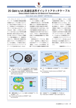
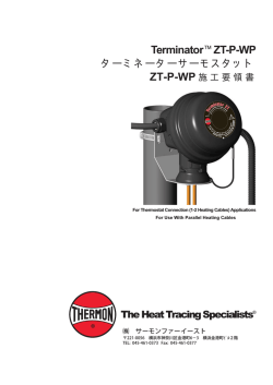
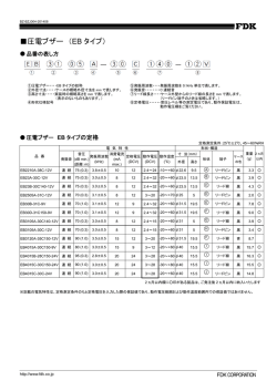
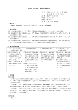
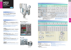
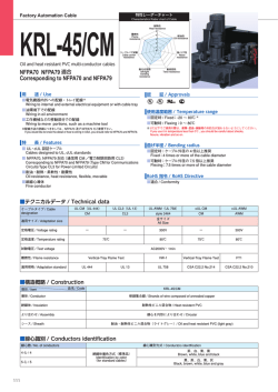
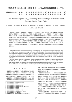
圧電式加速度ピックアップ PV-91C
取扱説明書
概 要
圧電式加速度ピックアップ P V -91C は、環状シェアタイプのエレメントと C C L D
方式( 定電流駆動方式)のチャージアンプを内蔵した小型圧電式加速度ピックアップ
であり、170℃までの温度環境においても加速度の検出が行えます。受感軸は 1 軸
で、軸方向は取り付け面に対する鉛直方向になっています。測定対象物への取り付
け方法は、ねじ止め( 標準取り付け方法)、付属の絶縁アタッチメント V P -53W を
介しての接着固定、両面テープなどがあります。付属の加速度ピックアップ用コー
ド V P -51L C、別売品の加速度ピックアップ用コード V P -51L / 耐熱ローノイズコー
ド VP-51LB が接続されます。
特徴
• C C L D 入力を持つ振動計や分析計、データレコーダなどの機器に接続して使用で
きます。
•(当社比)従来の CCLD 方式のピックアップより広い温度範囲(-50∼170℃)で振動
測定が行えます。
• 小型、軽量のため、測定対象物へのピックアップ質量の影響が小さく、軽量構造
物の振動測定やモード解析など、幅広く使用できます。
取り扱い上の注意
ピックアップと測定器類との接続
PV-91C と測定器類を付属のコア付き加速度ピックアップ用コード VP-51LC で接続し
ます。測定器側が BNC コネクタの場合は、別売品の BNC アダプタ VP-52C を介して
接続できます。P V -91C と V P -51L C を接続する際には、V P -51L C のコネクタの中心
コンタクトを PV-91C のコネクタの中心コンタクトに真っ直ぐ挿入して、VP-51LC の
接続リングをまわして締め付けてください。中心コンタクトが挿入されていなかった
り曲がった状態で接続リングを締め付けるとコネクタを破損させる場合があります。
VP-51LC の中心コンタクト周囲にはシリコンシートがはめ込まれています。PV-91C
と接続した際の密封性向上やがたつき防止に効果がありますが、使用温度範囲の上
限または下限付近の温度に長時間さらすと、まれにシリコンシートが変質し、密封
性やがたつき防止効果が劣化することがあります。シリコンシートが変質した場合は、
シートの交換をお勧めします。販売店または当社サービス窓口までご連絡ください。
P V -91C や V P -51L C のコネクタは汚さないように注意してください。汚れると、接
触不良などが発生し、測定に支障をきたす場合があります。万一汚れた場合はアル
コールなどで汚れを拭き落とした後、よく乾燥させてください。
加速度ピックアップ用コードの取り扱い
振動測定の際、付属のコア付き加速度ピックアップ用コード V P -51L C が変形、振動
および共振により断線する場合があります。P V -91C からできるだけ近い箇所で、粘
着テープなどを用いて V P -51L C を測定対象物に固定し、断線から V P -51L C を保
護することをお勧めします。また、ピックアップ用コードはコネクタの根元部分に
ストレスが集中しやすく、ストレスが加わり続けることで断線することがあります。
この部分には屈曲などの力が掛からないように、ご注意ください。
PV-91C本体
製品を安全にお使いいただくために、下記のことをお守りください。
重 要
VP-51LC
CCLD 方式に対応していない電源に接続しないでください。特に定電圧電源に接
続すると、内蔵のチャージアンプが壊れます。
• P V -91C を落下させないでください。P V -91C が破損したり、性能が劣化する場合
があります。また、取り付け面に傷が付いて周波数特性が悪くなる場合もあります。
• 使用温度範囲内でご使用ください。特に高温度では注意が必要です。使用温度範
囲を大きく超えると PV-91C が故障する可能性があります。
• PV-91C は防水構造ではないので、水の中に入れたり、高湿度環境に長時間置かな
いでください。ピックアップ内部に水が入り、絶縁低下によって性能が劣化する
ことがあります。
• P V -91C にゴミ・汚れが付着しないよう気を付けてください。汚れを取り除く場
合は、乾いたやわらかい布、またはぬるま湯で良く絞った布を使用してください。
• PV-91C 本体の中心コンタクトに針金、金属片などを押し込まないでください。
• 水やほこりのかかる場所や高湿度環境下での保管はしないでください。また、塩
分・硫黄分・化学薬品・ガスなどにより悪影響を受ける恐れのある場所での使用
や保管はしないでください。
• コードを取り外すときは、コードを持って引き抜くなど無理な力を掛けないで、
必ずプラグを持って外してください。
• 分解・改造はしないでください。
• ピックアップを振動体に取り付けると、ピックアップの質量が振動体に付加され
るので、振動モードが変化します。振動体の質量がピックアップの質量に対し
て 10 倍以上の場合には振動体の共振周波数の変化は 5%以下でほぼ無視できま
す。P V -91C の質量は 1.8 g ですので、測定対象となる振動体の質量は最小値で
18 g を目安にしてください。
• 故障、点検および修理の場合は、販売店または当社サービス窓口までご連絡ください。
• PV-91C を廃棄する場合は、国および地方自治体の法律、条例に従ってください。
外形・寸法
φ7
粘着テープ
測定対象物への取り付け方法
標準取り付け方法(VP-53K を用いた取り付け)
取り付け手順
1. 測定対象物に P V -91C を取り付けるため、M3 P =0.5 のネジ穴を開けます( 有効深
さ 3.5∼4 mm)
。
2. 付属の六角棒レンチで M3 ネジ V P -53K を P V -91C に入れて軽く締めます( 0.1∼
0.4 N・m)。
3. PV-91C を測定対象物に取り付けます。
4. 付属の片口スパナで締め付けます(締め付けトルク約 0.5 N・m)
。
5. 付属のコア付き加速度ピックアップ用コード VP-51LC をピックアップに取り付けます。
P V -91C と測定対象物を強く完全に密着させて固定することが重要です。ピックアッ
プ取り付け面に凸凹があると周波数特性が乱れる場合があります。取り付けると
きは滑らかな部分を選択するか、取り付け面を平らに仕上げてください。また、測
定対象物にネジ穴を開ける際、タップが斜めに立っていると密着性が悪く、周波数
特性が乱れることがあります。
付属の M3 ネジ以外は使用しないでください。強度不良や締め付け不良などで所定の
特性が出ない場合があります。
絶縁アタッチメント(VP-53W)
を用いた取り付け方法
P V -91C のケース( グランド)と測定対象物の取り付け面との間に電位差があると、グ
ランドラインに電流が流れ、動作が不安定になったり、ノイズが発生することがあ
ります。このような場合には付属の絶縁アタッチメント V P -53W を使用します。ま
た、測定対象物にネジ穴が無い場合にも V P -53W を使用して接着固定します。ただし、
V P -53W を使用する場合、使用温度上限は 160℃となります。160℃より高い温度環境
で使用すると、VP-53W 表面の絶縁層に微細なひびが入ることがあります。
取り付け手順
1. PV-91C に VP-53W を取り付け、付属の片口スパナで締め付けます( 締め付けトル
ク約 0.5 N・m)
。
5.9
3.8
12.5
2. 良好な接着性を確保するために、必要に応じて測定対象物の表面の汚れを取ります。
また、VP-53W の接着面も同様に表面の汚れを取ります。
3. 測定対象物に接着剤などを用いて接着します。接着および剥離に関しては接着剤な
どの取扱説明書に従ってください。
4. 接着剤が固まった時点で VP-51LC を取り付けます。
VP-53W を加工したり傷をつけたりしないでください。絶縁が保証できなくなります。
φ6.7
PV-91C
約8.1
M3 深さ2
VP-53K
VP-53W
(付属品)
(付属品)
ネジ加工
M3 P=0.5
D=3.5~4
7
10.1
単位:mm
*****は製造番号
接着面
熱過渡応答
PV-91C の代表諸特性
熱過渡応答は加速度ピックアップが温度変化した場合に発生する出力の変化です。
発生原因は圧電素子のパイロ(焦電効果:温度変化した場合に電荷が発生する現象)
と、構造の熱膨張による圧電素子へのストレスです。熱過渡応答はピックアップを
取り付ける振動体の温度変化で発生しますが、周囲の空気などの温度変化でも発生
することがあります。空気などが温度変化する場合にはカバーなどで覆うことに
よって低減できます。
周波数特性
40
Relative acceleration level [dB]
30
20
10
0
仕
-10
-20
様
適用法規制、規格
:PV-90C1+VP-53K(ねじ止め)
[1∼12000 Hz(±10%)at 23℃]
-30
-40
1
10
100
1000
10000
100000
Frequency [Hz]
方式
成分数
電圧感度
DC バイアス電圧
自己ノイズ
ベース歪み感度
Base distortion sensitivity [(m/s2)/μstrain]
0.10
0.08
0.06
周波数範囲
0.04
0.02
0.00
出力抵抗
最大測定加速度
-0.02
-0.04
※ 取り付け部に連続的かつ定量的歪みを加えた
ときの1μstrainあたりのPV-91C出力
-0.06
-0.08
-0.10
0
0.1
0.2
0.3
0.4
0.5
0.6
0.7
0.8
0.9
1
横感度比
ベース歪み感度
Time [s]
熱過渡応答
電圧感度の温度特性
駆動電源
Sensitivity temperature coefficient [%]
20.0
極性
15.0
10.0
ケース絶縁
固定方法
ケース材質
接続コード
5.0
0.0
-5.0
-10.0
-15.0
-20.0
-50
0
50
100
動作温度範囲
保存温度範囲
防水性
外形寸法
質量
付属品
150
Temperature [℃]
熱過渡応答
Thermal transient response [(m/s2)/℃]
1.00
0.80
0.60
温度衝撃を加えたポイント
0.40
0.20
0.00
-0.20
-0.40
※ PV-91Cに温度衝撃を加えたときの1℃あたり
のPV-91C出力
-0.60
-0.80
別売品
-1.00
0
1
2
3
4
5
6
Time [s]
EU-RoHS 指令、中国版 RoHS 指令、WEEE 指令
CE マーキング
(EMC 指令:2004/108/EC
EN 61326-1:2006/IEC 61326-1:2005)
※付属の VP-51LC と組み合わせた場合に適合
圧電式加速度検出 環状シェアタイプ
1 成分(取り付け面に直行する方向)
(at 80 Hz、23℃)
1 mV/(m/s2)
DC 7∼15 V(全温度範囲)
(23℃においては約 12.5 V)
20 µVrms(TYP.)
、40 µVrms(MAX.)
(1 Hz∼20 kHz、23℃)
-50∼150℃では 1 Hz∼20 kHz(± 10%)
150∼170℃では 1 Hz∼2 Hz(± 15%)、
2 Hz∼20 kHz(± 10%)
100 Ω以下
2
5000 m/s(Peak)
ただし、温度、電圧感度および駆動電源により異なる
5%以下(30 Hz)
0.006(m/s2)/µstrain(TYP.)、0.02(m/s2)/µstrain(MAX.)
(3 Hz HPF 使用時)
、0.1(m/s2)/℃(MAX.)
0.04(m/s2)/℃(TYP.)
(3 Hz HPF 使用時)
DC 18 V∼30 V(定電流 2∼4 mA)
定格 24 V
取り付け面から加速度ピックアップ側に向かう方向の加速度で
プラス電圧が出力
非絶縁
ネジ止め M3 ネジ
チタン合金
VP-51L、VP-51LB、VP-51LC
ただし、VP-51LC との組み合わせのみ CE マーキングに対応
-50∼170℃
-50∼170℃
非防水(測定、保管時に結露、腐食性ガスなきこと)
7 mm(六角の対辺)× 12.5 mm(H)
(コネクタ部を除く)
約 1.8 g
化粧ケース
1
コア付き加速度ピックアップ用コード
VP-51LC
1
M3 ネジ
VP-53K
2
絶縁アタッチメント
VP-53W
1
片口スパナ(7 mm 用)
1
六角棒レンチ
1
校正表
1
取扱説明書
1
内容品明細表兼リオン製品保証書
1
BNC アダプタ
VP-52C
加速度ピックアップ用コード
VP-51L
耐熱ローノイズコード
VP-51LB
仕様項目の説明と注意
http://www.rion.co.jp/
電圧感度
I S O 5347 に準拠するレーザ干渉法により標準圧電式加速度ピックアップ P V -03 を
絶対校正し、この加速度ピックアップを基準にして PV-91C を比較校正しています。
感度校正の基準周波数は 80 Hz です。
周波数範囲
PV-03 のような基準となる加速度ピックアップとの比較測定で PV-91C の周波数特
性を測定しています。周波数特性は 80 Hz を基準にしています。PV-91C の共振周
波数はおよそ 55 kHz にあります。周波数範囲の下限は PV-91C の取り付け方法に
ほとんど依存しません。
横感度比
受感軸方向の感度を基準にしたときの、加速度ピックアップの受感軸に直行する
面に対する感度が横感度比です。横感度比は主に材料や組立におけるわずかな角度
ずれが原因となります。特定の方向の振動が大きく、これと直行する方向の小さな
振動を測定する場合には横感度比を考慮する必要があります。
ベース歪み
圧電式加速度ピックアップは、取り付け部が歪むとノイズを発生したり感度が変化
します。ピックアップの取り付け部に余計な力が加わらないように、ピックアッ
プは平坦でかつ歪みにくい剛体面に取り付けてください。
本社/営業部
東京都国分寺市東元町 3 丁目 20 番 41 号
〠 185-8533
TEL(042)
359-7887(代表)
FAX(042)359-7458
サービス窓口
リオンサービスセンター株式会社
東京都八王子市兵衛 2 丁目 22 番 2 号
〠 192-0918
TEL(042)
632-1122 FAX(042)
632-1140
東日本営業所
さいたま市南区南浦和 2-40-2 南浦和ガーデンビルリブレ
〠 336-0017
TEL(048)
813-5361 FAX(048)
813-5364
西日本営業所
大阪市北区梅田 2 丁目 5 番 5 号 横山ビル 6F
〠 530-0001
TEL(06)
6346-3671 FAX(06)
6346-3673
東海営業所
名古屋市中区丸の内 2 丁目 3 番 23 号 和波ビル
〠 460-0002
TEL(052)
232-0470 FAX(052)
232-0458
九州リオン(株)
福岡市博多区店屋町 5-22 朝日生命福岡第 2 ビル
〠 812-0025
TEL(092)
281-5366 FAX(092)
291-2847
PIEZOELECTRIC ACCELEROMETER
PV-91C
INSTRUCTION MANUAL
Accelerometer cable handling precautions
During a vibration measurement, the supplied cable with 10-32 UNF connectors
and ferrite cores VP-51LC may become deformed or break due to the influence
of vibrations and resonance. To prevent this, the VP-51LC should be fi xed to the
measurement object with adhesive tape or similar, at a point as close to the PV-91C
as possible. Also, note that stress which tends to occur at the base of the connector
can cause the cable to break if present for an extended time. Handle the cable with
care and avoid subjecting this section to bending force etc.
PV-91C
http://www.rion.co.jp/english/
3-20-41 Higashimotomachi, Kokubunji, Tokyo 185-8533, Japan
Outline
The PV-91C is a compact piezoelectric accelerometer featuring an annular shear mode
element and a CCLD (constant current line drive) type charge amplifier. The PV-91C
is allowed acceleration measurements in temperature environments up to 170°C.
The PV-91C has one detection axis perpendicular to the mounting surface. Various
mounting methods are supported, including screw mounting (standard method), adhesive
mounting using the supplied insulation attachment VP-53W, dual-sided adhesive tape,
etc. The supplied cable with 10-32 UNF connectors and ferrite cores VP-51LC is to
be connected to the PV-91C. Also the optional low-noise coaxial cable (heat-resistant)
VP-51LB and accelerometer cable VP-51L are used for connection.
Features
• Connects for use with devices such as a data recorder, analyzer and vibration
meter which has CCLD input.
• Performs vibration measurement in the wider temperature range than the traditional accelerometer of the CCLD system.
• Because of the compact and lightweight design, there is little accelerometer mass
interference with the object being measured and it can be used for a wide variety
of applications such as vibration measurement and modal analysis of lightweight
structural objects.
Precautions
In order to ensure safety, carefully read and observe the precautions below.
Important
Do not connect the PV-91C to a power supply that is not CCLD
compliant. In particular, connecting the PV-91C to a constant
voltage power supply may cause permanent damage to the unit.
• Take care not to drop the PV-91C, to prevent the risk of damage and performance degradation. If the mounting surface is damaged, frequency response may also suffer.
• Use the PV-91C only within its specified operation temperature range. In particular, protect
the unit from excessively high temperatures. Otherwise, the PV-91C may be damaged.
• The PV-91C is not waterproof. Do not immerse the unit in water or expose it to a
high humidity environment for an extended time. Otherwise water may enter the
unit and performance may be degraded due to reduced grounding.
• Be careful there is no adhesion of dust and dirt to the PV-91C. Clean the PV-91C
only by wiping it with a soft, dry cloth or, when necessary, with a cloth lightly
moistened with water.
• Do not insert any objects such as pins, metal scraps etc. into center contact of the
PV-91C.
• Protect the unit from water, dust and extreme humidity during storage. Also keep
the unit away from air with high salt or sulphur content, gases, and stored chemicals
during storage and use.
• When disconnecting cables, always grasp the plug and do not pull the cable. Do
not apply excessive force.
• Do not try to disassemble or alter the unit.
• When the PV-91C is mounted to a measurement object, the mass of the accelerometer will be added to that of the object, thereby changing its vibration mode.
Provided that the mass of the measurement object is at least 10 times of the accelerometer, the change in resonance frequency will be 5 percent or less and can
therefore largely be disregarded. Since the PV-91C has a mass of 1.8 grams, the
measurement object should have a mass of at least 18 grams.
• In case of a malfunction, checks and servicing contact the supplier.
• When disposing of the PV-91C, please follow the local and national government
regulations and laws.
VP-51LC
Adhesive tape
Method of mounting to an object to be measured
The standard mounting method using the VP-53K
Installation procedure
1. Drill a hole (M3 P=0.5) into the measurement object for attaching the PV-91C
(effective depth 3.5 to 4 mm).
2. Insert the M3 screw VP-53K into the PV-91C and use the supplied hex wrench to
lightly tighten it (0.1 to 0.4 N · m).
3. Attach the PV-91C to the measurement object.
4. Use the supplied spanner to fasten the PV-91C (fastening torque approx. 0.5
N · m).
5. Connect the supplied cable with 10-32 UNF connectors and ferrite cores VP51LC to the accelerometer.
It is important that the PV-91C adheres tightly and hermetically to the measurement object. If the surface to which the accelerometer is mounted is not smooth,
frequency response may be affected. Either select a section that is already flat
and smooth, or fi nish the section to a suitable condition prior to mounting. When
opening a screw mounting hole in the measurement object, the tap must be applied
completely vertically, to ensure a tight fit of the accelerometer and prevent impairment of frequency response.
Do not use any other screw except the supplied M3 screw. Otherwise the required
strength and tight fit may not be achieved.
The mounting method using the insulation attachment VP-53W
If an electric potential exists between the housing (ground) of the PV-91C and
the measurement object, a current may flow in the ground line, which can lead to
unstable operation and noise. In such a case, use the supplied insulation attachment
VP-53W. The attachment can also be used to attach the PV-91C if there should be
no screw hole in the measurement object.
However, when using the VP-53W, the upper temperature limit for use of the PV91C is reduced to 160°C. If used in environment higher than 160°C, the insulating
layer of the VP-53W may develop microscopic cracks.
Installation procedure
1. Attach the VP-53W to the PV-91C and use the supplied spanner to fasten it
(fastening torque approx. 0.5 N · m).
2. Make sure that the surface of the measurement object is clean, to ensure a good
adhesive fit. Also clean the mounting surface of the VP-53W.
3. Use a suitable adhesive to glue the VP-53W with PV-91C to the measurement
object. For information on the proper procedure for gluing and detaching, refer
to the instructions of the adhesive in use.
4. After the adhesive has fully set, connect the VP-51LC to the accelerometer.
Do not modify or damage the VP-53W. Otherwise proper isolation may not be
achieved.
Accelerometer and measurement unit connection
Use the supplied cable with 10-32 UNF connectors and ferrite cores VP-51LC to
connect the PV-91C to the measurement device. If the measurement device has a
BNC connector, the optional BNC adapter VP-52C can be used. When connecting the VP-51LC to the PV-91C, insert the plug straight and make sure that the
center contact of the VP-51LC is engaged with the corresponding center contact
of the PV-91C connector. Then turn the ring to tighten the connection. If the ring
is tightened while the center contact is not properly inserted or positioned at an
angle, the connector may be damaged.
The center connector of the VP-51LC is enclosed by a silicon pad that serves to
ensure a tight fit and prevent wobbling when connected to the PV-91C. In rare cases,
when the unit is exposed to temperatures near the limits for extended periods, the
silicon pad may deteriorate and lose its effect. If this has happened, the pad should
be replaced. Contact the supplier.
When handling the parts, take care not to get the PV-91C or VP-51LC dirty. Otherwise,
contact problems may impair the measurement. If a part has become contaminated,
wipe it with cleaning alcohol or similar and use it only after it has full dried.
PV-91C
VP-53K
(supplied)
Drill screw hole
M3 P = 0.5 mm
D = 3.5 to 4 mm
VP-53W
(supplied)
Gluing surface
Specifications
Typical response of the PV-91C
Standard compliance
10
0
-10
:PV-91C+VP-53K (Screw)
[1 to 12000 Hz (±10%) at 23°C ]
-20
-30
-40
1
10
100
1000
10000
100000
Frequency [Hz]
Base distortion sensitivity
Base distortion sensitivity [(m/s2)/ strain]
0.10
0.08
0.06
0.04
0.02
0.00
-0.02
-0.04
* PV-91C output per 1 strain when continuous and
quantitative strain is applied to mounting section
-0.06
-0.08
-0.10
0
0.1
0.2
0.3
0.4
0.5
0.6
0.7
0.8
0.9
1
Time [s]
Temperature characteristics of voltage sensitivity
Sensitivity temperature coefficient [%]
20.0
15.0
10.0
5.0
0.0
-5.0
-10.0
-15.0
-20.0
-50
0
50
100
150
Temperature [°C]
Thermal transient response
Thermal transient response [(m/s2)/°C]
1.00
0.80
0.60
Thermal shock point
0.40
0.20
0.00
-0.20
-0.40
* PV-91C output per 1°C when a rapid fluctuation in
ambient temperature is applied to PV-91C
-0.60
-0.80
-1.00
0
1
2
3
4
5
6
Time [s]
Explanation and notes about specification items
Voltage sensitivity
The reference piezoelectric accelerometer PV-03 absolutely calibrated by ISO 5347
compliant laser interferometry is used for comparative calibration of the PV-91C.
The reference frequency for sensitivity calibration is 80 Hz.
Vibration frequency range
The frequency response of the PV-91C is measured through comparison to a reference accelerometer such as the PV-03. Frequency response is referenced to 80
Hz. The resonance frequency of the PV-91C is located at approximately 55 kHz.
The lower limit of the PV-91C's vibration frequency range is largely unaffected
by the mounting method.
Transverse response
This is the response of the accelerometer on an axis that is orthogonal to the sensitive
axis. It is largely due to material properties and slight angle shifts during assembly
of the accelerometer. If there is large vibration from a specific direction and vibrations on an axis right angle to it are to be measured, the transverse response must
be taken into consideration.
Base distortion
When the mounting section of a piezoelectric accelerometer is subject to strain, noise
and sensitivity changes may occur. The accelerometer should therefore be mounted
on a sturdy and flat surface that is not susceptible to distortion due to strain.
Thermal transient response
This refers to the change in output that occurs when the temperature of the accelerometer changes. It is caused by the pyroelectric effect which produces an electrical
charge when temperature fluctuates, and by stresses exerted on the piezoelectric
element due to structural thermal expansion. Thermal transient response normally
occurs when the temperature of the vibrating object to which the accelerometer is
mounted changes, but it can also arise due to changes in the ambient temperature.
If the air in the measurement location is subject to temperature changes, the effect
can be reduced by providing a cover or similar for the accelerometer.
Outside views
7
5.9
20
3.8
Relative acceleration level [dB]
30
12.5
40
EU RoHS Directive, China RoHS, WEEE Directive
CE mark
(EMC Directive: 2004/108/EC
EN 61326-1: 2006/IEC 61326-1: 2005)
*When combined with supplied VP-51LC
Method
Piezoelectric accelerometer detection, annular shear mode
Axis
1 axis (perpendicular to mounting surface)
Voltage sensitivity
1 mV/(m/s2) (at 80 Hz, 23°C)
DC bias voltage
7 V to 15 V DC (all temperature range)
(approx. 12.5 V at 23°C )
Residual noise
20 µVrms (TYP.), 40 µVrms (MAX.) (1 Hz to 20 kHz, 23°C)
Vibration frequency range
1 Hz to 20 kHz (±10%) at -50°C to 150°C
1 Hz to 2 Hz (±15%), 2 Hz to 20 kHz (±10%) at 150°C
to 170°C
Output resistance
100 Ω or less
Maximum measurable acceleration
5000 m/s2 (peak)
Differ according to temperature, voltage sensitivity and
supply voltage
Transverse response 5% or less (30 Hz)
Base distortion sensitivity
0.006 (m/s2)/µstrain (TYP.), 0.02 (m/s2)/µstrain (MAX.)
(using 3 Hz high-pass fi lter)
Thermal transient response
0.04 (m/s2)/°C (TYP.), 0.1 (m/s2)/°C (MAX.)
(using 3 Hz high-pass fi lter)
Supply voltage
18 V to 30 V DC (constant current 2 to 4 mA)
Rated voltage 24 V
Polarity
Acceleration in the direction from the mounting surface to
the accelerometer generates positive output voltage
Grounding
Non-insulated
Mounting
Screw mounting, M3 screw
Case material
Titanium alloy
Connection cable
VP-51L, VP-51LB, VP-51LC
Conform to CE marking only when combined with VP-51LC
Operating temperature range
-50°C to +170°C
Storage temperature range
-50°C to +170°C
Waterproofi ng
Non-waterproof (unit must be protected from condensation
and corrosive gases during storage and measurement)
Dimensions
7 mm (hex width across flats) × 12.5 mm (H)
(excluding connector)
Mass
Approx. 1.8 g
Supplied accessories
Case
1
Cable with 10-32 UNF connectors and ferrite cores
VP-51LC 1
M3 screw
VP-53K
2
Insulation attachment
VP-53W
1
Spanner (for 7 mm)
1
HEX wrench
1
Calibration chart
1
Instruction manual
1
Inspection certificate
1
Optional accessories
BNC adapter
VP-52C
Accelerometer cable
VP-51L
Low-noise coaxial cable (heat-resistant)
VP-51LB
6.7
M3 depth 2
Approx. 8.1
Frequency response
7
10.1
unit: mm
***** is the serial number.
No. 56950 12-03
© Copyright 2026 Paperzz