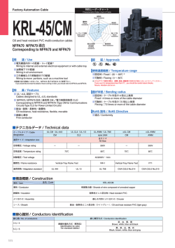
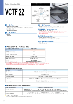
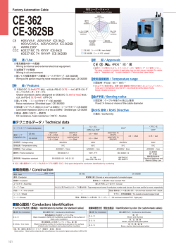
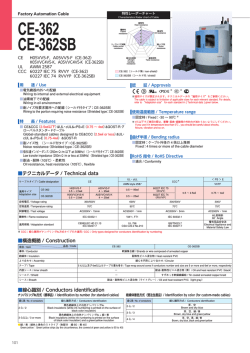
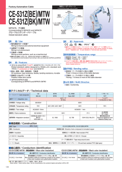
特性レーダーチャート
Factory Automation Cable
Characteristics Rader chart of Cable
CE-531NZ
CE-531NZSB
耐熱性
Heat resistance
5
難燃性
Flame
resistance
4
3
耐油性
Oil resistance
2
1
0
ケーブルベア試験
Cable carrier
resistance
CE
UL AWM 2587
耐左右屈曲
left/right
bending
resistance
耐ノイズ性
Noise
resistance
耐捻回性
Twist resistance
CE-531NZ(シールド無 / non-shield)
CE-531NZSB(シールド付 / shield)
用 途 / Use
認 証 / Approvals
■ケーブルベア,ロボットへの配線
Wiring to cable carriers and robots
■油環境下での配線
Wiring in oil environment
■耐ノイズ性要求箇所への配線(シールド付タイプ:CE-531NZSB)
Wiring to the portion requiring noise resistance(Shielded type:CE-531NZSB)
※
※適用サイズが限定されます。テクニカルデータの“適用サイズ”をご参照ください。
The cable is subject to limitation of applicable sizes for each relevant standard. For details,
refer to “Adaptation size” for each standard in [ Technical data ] given below.
使用温度範囲 / Temperature range
■固定時 / Fixed:-30 〜 90℃ ※
■可動時 / Flexing:0 〜 90℃
特 長 / Features
※ 0℃以下でご使用の際は、衝撃・屈曲・振動等の外的力が加わらないようにしてください。
If you use it in temperature less than 0℃ , you should be careful about shocks,
flexure, vibration and so on.
■ CE&UL・cUL&<PS>E(0.75 〜 2.5㎟)&GOST-R グローバルスタンダ
ードケーブル
Global-standard cables designed to CE, UL, cUL, <PS>E(0.75-2.5㎟)and GOST-R
■耐ノイズ性(シールド付タイプ:CE-531NZSB)
Noise resistance(Shielded type:CE-531NZSB)
■耐油・耐熱(105℃)・柔軟・耐屈曲性 可動用
Oil resistance, heat resistance(105℃), flexible, bending resistance, movable
■素線径 0.08㎜可とうより線(中心補強紐入り)
Flexible 0.08㎜ wire strand (containing reinforcement cord at its center)
曲げ半径 / Bending radius
■固定時:ケーブル外径の 4 倍以上推奨
Fixed:4 times or more of the cable diameter
■可動時:ケーブル外径の 7.5 倍以上推奨
Flexing:7.5 times or more of the cable diameter
RoHS 指令 / RoHS Directive
■適合 / Conformity
■テクニカルデータ / Technical data
CE
ケーブルタイプ / Cable designation
UL・cUL
CE-531NZ
MA-AA
適用サイズ / Adaptation size
AWM style 2587
VCTF
全サイズ / All Size
0.75 〜 2.5 ㎟
300/500V
600V
300V
70℃
90℃
75℃
AC2000V・15min
AC3000V・1min
AC2000V・1min
IEC 60332-1
VW-1, FT1
CENELEC HD 21.13 に準ずる
VDE 0281-13
UL 758
CSA C22.2 No.210
定格電圧 / Voltage rating
難燃性 / Flame resistance
適用規格 / Adaptation standard
< PS > E
全サイズ / All Size
定格温度 / Temperature rating
試験電圧 / Test voltage
CE-531NZSB
MA-BB
60 度傾斜
60°Angle
電気用品安全法
Electrical Appliance and Material Safety Law
■構造概略 / Construction
項目 / Item 導体 / Conductor
品名 / Code
CE-531NZ
CE-531NZSB
軟銅複合より線(中心補強紐入り)/ Rope-lay stranded of annealed copper (containing reinforcement cord at its center)
絶縁体 / Insulation
耐熱性ビニル混合物 / Heat resistant PVC
より合わせ / Assembly
線心を円形により合わせ / Circular
5 心以上はテープを重ね巻き / Tape wrap around cores if conductors are 5 or more
テープ / Tape
内部シース / Inner sheath
−
耐油・耐熱性ビニル混合物(黒)/ Oil and heat resistant PVC(black)
シールド / Shield
−
すずめっき軟銅線編組 / Tin coated annealed copper braid
シース / Sheath
耐油・耐熱性ビニル混合物(ライトグレー)/ Oil and heat resistant PVC (light gray)
■線心識別 / Conductors identification
線心数 / No. of conductors
2心/2
3 心以上 / 3 or more
線心識別方式 / Conductors identification
ナンバリング No. 方式
Identification by number
黒色絶縁体上の白色ナンバリング№
Black insulations (white ink numbering is printed on the surface of black color insulation)
黒色絶縁体上の白色ナンバリング№ + 緑 / 黄
Black insulations (white ink numbering is printed on the surface of black color insulation) and a green/yellow insulation
●緑 / 黄:緑色と黄色のストライプ(色配分 緑 60:黄 40)/ Green/yellow : Green/yellow strips (by the circumference, the covered of green and yellow is 60 to 40)
■例示 / Example : CE-531NZ 3 × 1㎟(18AWG)
CE-531NZ KURAMO-K VDE Reg.-Nr. 8369 CE MA-AA 300/500V 1㎟(18AWG)
KURAMO E162205-K
AWM STYLE 2587 I / Ⅱ A/B 90C 600V VW-1 FT1
VCTF <PS>E JET タイネツ 300V GOST-R LF
2
1
補強紐 / Reinforcement cord
99
導体 / Conductor 絶縁体 / Insulation
シース / Sheath
■構造表 / Construction table
導体 / Conductor
絶縁 / Insulation
外径(約㎜)
公称断面積
外径(約㎜)
Diameter
Nominal cross (Approx.㎜) Diameter
sectional area
(Approx.㎜)
構成
Construction
〈
0.5㎟
<20AWG>
0.75㎟
<18AWG>
1.5㎟
<16AWG>
1.5
<6/28/0.08>
1.6
<6/35/0.08>
2.05
<6/52/0.08>
3.25
3.4
3.85
4.3
○
○
○
○
○
○
○
○
○
○
○
○
○
○
○
○
○
○
○
○
○
○
○
○
○
○
○
○
○
○
○
○
○
○
○
○
○
○
○
○
○
○
○
○
○
○
○
○
○
○
○
○
○
○
○
○
○
○
○
○
○
○
○
○
○
○
○
○
11.0
11.5
12.5
14.0
14.5
15.5
16.5
18.0
17.5
19.0
23.5
24.5
27.0
12.0
12.5
13.5
15.0
16.0
17.0
18.0
21.0
20.0
23.0
26.0
27.0
30.0
12.5
13.0
14.0
15.5
16.5
17.5
19.0
21.0
20.5
23.5
27.0
28.0
31.5
13.5
14.0
15.0
16.5
18.0
19.0
20.5
24.0
23.5
25.5
29.5
32.0
34.5
15.0
15.0
16.0
18.0
19.0
21.0
23.0
26.5
25.5
28.0
32.5
34.5
37.5
165
175
205
235
265
295
330
390
390
475
660
750
880
190
210
250
285
325
360
395
510
495
660
830
945
1100
205
235
270
310
350
390
445
530
550
710
910
1040
1250
245
280
325
360
415
480
540
700
730
875
1130
1330
1570
290
335
395
455
520
600
720
890
920
1120
1500
1710
2030
10
9
8
7
7
7
7
6
6
5
5
5
4
13
11
10
9
9
9
8
8
7
7
6
6
5
15
13
12
11
11
10
10
9
9
8
7
7
6
20
17
15
14
14
13
13
12
11
10
9
9
8
27
23
21
20
19
18
18
16
15
14
13
12
11
39.0 以下
(Max 39.0)
50 以上
(Min 50)
26.0 以下
(Max 26.0)
50 以上
(Min 50)
19.5 以下
(Max 19.5)
50 以上
(Min 50)
13.3 以下
(Max 13.3)
50 以上
(Min 50)
7.98 以下
(Max 7.98)
40 以上
(Min 40)
cUL/CSA
cUL/CSA
○
100
110
130
145
165
185
215
260
265
320
430
550
650
120
140
165
180
210
240
270
345
345
420
630
710
850
135
150
180
205
235
265
300
380
390
470
690
790
960
160
185
225
245
290
330
380
465
500
660
890
1020
1240
200
250
290
325
380
440
490
680
720
870
1190
1370
1660
絶縁抵抗
導体抵抗
Insulation
Conductor
resistance
resistance
20℃
(Ω / ㎞) 20℃
(M Ω㎞)
NFPA70
NFPA70
NFPA79
NFPA79
9.0
9.4
10.5
11.5
12.5
13.0
14.0
16.0
15.5
16.5
19.5
22.0
24.0
9.9
10.5
11.5
12.5
13.5
14.5
15.5
18.5
17.5
19.0
23.5
24.5
27.0
10.5
11.0
12.0
13.0
14.0
15.0
16.5
18.5
18.0
19.5
24.5
25.5
28.5
11.0
12.0
13.0
14.0
15.5
16.5
18.0
20.5
19.5
23.0
26.5
28.5
31.5
12.0
13.0
14.0
15.5
17.0
18.5
19.5
23.5
23.0
25.0
29.5
31.0
34.0
電気特性 / Electrical characteristics
許容電流
Allowable
ampacity
(A)
UL
UL AWM
AWM
2.5
<6/86/0.08>
2.8
シールド付き / Shield
シース外径(約㎜)
概算重量
Sheath diameter Approx.weight
(Approx.㎜)
(kg/ km)
<<PS
PS>>EE
2.5㎟
<14AWG>
1.1
<6/18/0.08>
2
3
4
5
6
7
8
10
12
15
21
25
31
2
3
4
5
6
7
8
10
12
15
21
25
31
2
3
4
5
6
7
8
10
12
15
21
25
31
2
3
4
5
6
7
8
10
12
15
21
25
31
2
3
4
5
6
7
8
10
12
15
21
25
31
シールド無し / Non-shield
シース外径(約㎜)
概算重量
シールド無 シールド付
Sheath diameter Approx.weight
Non-shield Shield
(Approx.㎜)
(kg/ km)
CE-531NZ
CE-531NZSB
1㎟
<18AWG>
〉
在庫 / Stocks
心数
Number of
conductors
○は在庫品です。/ ○:Stocks
CE
CE
■許容電流について / Allowable ampacity
・許容電流値は周囲温度 30℃、空中 1 条敷設時の計算値を示し、保証値ではありません。
Allowable ampacity (A) for cable is based on calculation under aerial one-cable and temperature at 30℃ , not repressenting a guaranteed value.
・周囲温度 30℃以上の場合は、次の電流減少係数を表の値に乗じて下さい。
Allowable ampacity cable at ambient temperature abobe 30℃ is to be determined by multiplying the current value by the appropriate current reduction factorin the following table1.
CCC
CCC
・許容電流の値は、JCS0168 により算出した値であって、保証値ではありません。/ The allowable ampacity for cable are the calculated by JCS0168, but not guaranteed.
・欧州では、建物の電気設備の配線システムの許容電流に関しての規格“IEC 60364-5-52(Electrical installations of buildings-Part 5-52:Selection and erection of electrical equipment - Wiring systems)”がありますのでご参照下さい。
For details on Allowable ampacity of the cable when used in Europe, refer to the applicable standard“IEC 60364-5-52 (Electrical installations of buildings - Part 5-52:Selection and erection of electrical equipment - Wiring systems)”
GOST-R
GOST-R
JCS0168…日本電線工業会規格“33kV 以下電力ケーブルの許容電流計算”
“Calculation of the current rating of power cables for rated voltage up to and including 33kV”
■表 電流減少係数 / Table1 Current reduction factorss
周囲温度 / Ambient temperature(℃)
電流減少係数 / Current reduction factors
30
1.00
35
0.94
40
0.87
45
0.79
50
0.71
55
0.61
60
0.5
65
0.35
100
© Copyright 2026 Paperzz