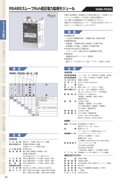
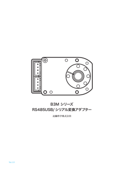
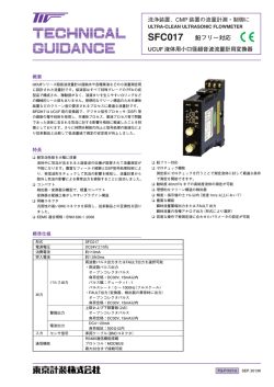
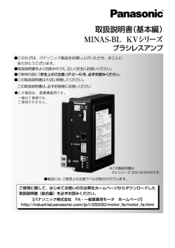
RS485 通信カード「OPC-F1-RS」
RS485 通信カード「OPC-F1-RS」をお買上げいただきましてありがとうございます。この通信カードを FRENIC-Eco に取り付
けることで,インバータ本体の RS485 通信(タッチパネル接続用 RJ45 ポート)に加え,以下の機能拡張が可能になります。
・ホスト機器からのコントロール
パソコンや PLC などのホスト機器と接続し,FRENIC-Eco を下位機器としてコントロールすることができます。
本 RS485 通信カードはタッチパネル/パソコンローダと接続することはできません。
2. 取付け方法
取付け・配線は電源を遮断して 30kW 以下は5分以上,37kW 以上は 10 分以上経過してから行ってください。更に LED モニ
タおよびチャージランプの消灯を確認し,テスターなどを使用して主回路端子 P(+)-N(-)間の直流中間回路電圧が安全な
値(DC+25V 以下)に下がっていることを確認してから行ってください。
感電のおそれあり
通信プロトコルとして,富士汎用インバータプロトコルおよび Modbus RTU プロトコルを準備しています。プロトコルの
詳細は RS485 通信ユーザーズマニュアル(MHT271a 以降)を参照してください。
(1) インバータが複数台接続されている場合,終端となるインバータに取り付ける RS485 通信カードの SW103(終端抵抗
入り切りスイッチ)(図1)は必ず ON にしてください。(出荷時は OFF)
(2) インバータ本体のカバーを取り外し,制御プリント基板を露出してください。(図3)
FRENIC-Eco 取扱説明書(INR-SI47-0852)の「2.3 配線」を参照してカバーを取り外してください。(37kW 以上はタ
1. 製品の確認
ッチパネルケースも開けてください。)
次の項目を確認してください。
(1) RS485 通信カードが入っていることを確認してください。
(2) RS485 通信カード上の部品の異常,凹み,反りなど輸送時での破損がないことを確認してください。
(3) OPC-F1-RS の裏面(図2)のスペーサ(4個)と CN1 をインバータ本体の制御プリント基板のスペーサ取付け穴と Port
A(CN4)へ差し込んでください。(図4)
スペーサと CN1 が確実に差し込まれていることを目視確認してください。(図5)
(3) RS485 通信カード上に形式「OPC-F1-RS」が印刷されていることを確認してください。(図1)
製品にご不審な点や不具合などございましたら,お買上げ店または最寄りの弊社営業所までご連絡ください。
(4) OPC-F1-RS の配線を行います。
配線方法・使用方法などは RS485 通信ユーザーズマニュアル(MHT271a 以降)を参照してください。
(5) インバータ本体のカバーを元に戻してください。
FRENIC-Eco 取扱説明書(INR-SI47-0852)の「2.3 配線」を参照してカバーを取り付けてください。(37kW 以上はタ
ッチパネルケースも閉じてください。)
図1 カード表面
図2
カード裏面
図3
FRN7.5F1S-2J∼
FRN15F1S-2J の例
富士電機システムズ株式会社
図4
カードの取付け
図5
取付け完了
ドライブ事業本部
〒108-0075 東京都港区港南2丁目4番13号(スターゼン品川ビル)
URL
http://www.fesys.co.jp/
発行
富士電機システムズ株式会社
技術相談窓口
TEL:0120-128-220
鈴鹿工場
〒513-8633
三重県鈴鹿市南玉垣町 5520 番地
FAX:0120-128-230
INR-SI47-0872a-JE
- 1 -
- 2 -
Installation Manual
RS485 Communications Card "OPC-F1-RS"
Thank you for purchasing the RS485 Communications Card OPC-F1-RS. Installing this card on your FRENIC-Eco series of inverters
enables RS485 communication (via the RJ45 port for communication with a keypad) on the inverter plus the following expanded feature:
• Control from host equipment
This feature allows you to connect your FRENIC-Eco to host equipment such as a personal computer or PLC, so that the FRENIC-Eco can
be treated as a device subordinate to the host.
The RS485 Communications Card can be connected neither to a keypad nor to PC loader.
2. Installation
Turn the power off and wait for at least five minutes for models of 30 kW or below, or ten minutes for models of 37 kW or above, before
starting installation. Further, check that the LED monitor is unlit, and check the DC link circuit voltage between the P (+) and N (-)
terminals to be lower than 25 VDC.
Otherwise, electric shock could occur.
Two communication protocols are available for the RS485 Communications Card: Fuji general-purpose inverter protocol and the
Modbus RTU protocol. For details, refer to the RS485 Communications User's Manual (MEH448a or later).
(1) If more than one inverter is connected in your network and you are going to install the RS485 Communications Card on the
inverter at the network end, then be sure to turn SW103 (switch for connecting/disconnecting the terminating resistor) (shown in
Figure 1) to the ON position. The factory default is OFF.
(2) Remove the cover from the inverter and expose the control circuit board (See Figure 3.).
To remove the inverter cover, refer to Section 2.3 "Wiring" of FRENIC-Eco Instruction Manual (INR-SI47-0882-E). For
capacities of 37 kW or above, open also the keypad enclosure.
1. Check that:
(3) Insert the four spacers and CN1 on the back of the OPC-F1-RS into the four spacer holes and Port A (CN4) on the control circuit
board in the inverter (See Figure 4.).
(1) An RS485 Communications Card is contained in the package.
(2) The RS485 Communications Card has not been damaged during transportation--no defective electronic devices, dents, or warp.
Visually check that the spacers and CN1 are firmly inserted (See Figure 5.).
(3) The model name "OPC-F1-RS" is printed on the RS485 Communications Card. (See Figure 1.)
If you suspect the product is not working properly or if you have any questions about your product, contact your Fuji Electric representative.
(4) Connect the associated cables between the OPC-F1-RS and the network.
For details of cabling, refer to RS485 Communications User's Manual (MEH448a or later).
(5) Put the cover back to the inverter.
To put back the converter cover, refer to Section 2.3 "Wiring" of FRENIC-Eco Instruction Manual (INR-SI47-0882-E). For
capacities of 37 kW or above, close also the keypad enclosure.
Figure 1 Front of Card
Figure 2 Back of Card
Figure 3 In the case of
FRN7.5F1S-2J thru
FRN15F1S-2J
Figure 4 Mounting Communications Card
Figure 5 Mounting Completed
Fuji Electric Systems Co., Ltd.
Gate City Ohsaki, East Tower 11-2, Osaki 1-chome, Shinagawa-ku, Tokyo, 141-0032, Japan
Phone: +81 3 5435 7283
URL
Fax: +81 3 5435 7425
http://www.fesys.co.jp/eng/
INR-SI47-0872a-JE
-1-
-2-
© Copyright 2026 Paperzz