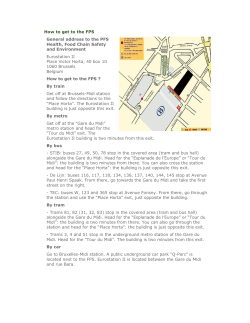
DR5033 BOOSTER 3 AMP DR5033 HANDLEIDING / MANUAL BEDIENUNGSANLEITUNG / MANUEL V1.0 11-2014 © Copyright 2005 – 2015. The Netherlands. All rights reserved. No information, images or any part of this document may be copied without the prior written permission of digikeijs. www.digikeijs.com P1 DR5033 BOOSTER 3 AMP CDE ingang CDE input CDE Eingang CDE entrée LNET aansluiting LNET connection LNET Anschluss LNET connexion B-BUS aansluiting B-BUS connection B-BUS Anschluss B-BUS connexion Rails sniffer Rails sniffer Rails sniffer Rails sniffer Voeding aansluiting Power connection Stromanschluss Connecteur de puissance HBRIDGE uitgang HBRIDGE output HBRIDGE ausgang HBRIDGE sortie Signaal OK Geen signaal Belasting Belasting boven 90% Kortsluiting STOP commando Fase polariteit Signal OK No signal Current load Current load above 90% Short circuit STOP command Phase polarity Signal OK Kein Signal Strombelastung Strombelastung über 90% Kurzschluss STOP Befehl Phasenpolarität Le signal OK Pas de signal Charge de courant Charge de courant plus de 90% Court-circuit www.digikeijs.com Commande sur STOP Polarité de phase P2 DR5033 BOOSTER 3 AMP Beschrijving van het product De DR5033 is een 3-Ampere, H-brug DCC booster met meerdere aansluitmogelijkheden op een al beschikbare digitale centrale. De DR5033 beschikt over een aantal unieke mogelijkheden. Zo kan de booster autonoom zijn uitgang ompolen (fase-draaiing) als een foute aansluiting op de rail geconstateerd wordt die anders kortsluiting zou opleveren. De booster kan op verschillende systemen aangesloten worden. Zo beschikt de DR5033 over CDE (Lenz), B-BUS (Roco), L.NET-T (Intellibox) en Railsniffer (PIKO Digi1, EcOS etc.) ingangen. Daarnaast kan de booster middels L.NET LNCV programmering zeer flexibel ingesteld worden op uw eigen situatie. Aangesloten op L.NET kan de DR5033 optioneel aan- en uitgeschakeld worden middels, naar keuze, de STOP-GO knoppen op de centrale of via een (configureerbaar) wisseladres. Ook meldt de booster dan zijn status aan de centrale via L.NET en kunnen via LNCV de belasting (0-100%) en de temperatuur van de H-brug in ‘C uitgelezen worden. Eveneens op L.NET aangesloten kan de DR5033 ‘luisteren’ naar een configureerbaar wisseladres, waarmee de uitgang van de booster omgepoold kan worden. Bovendien beschikt de booster over de mogelijkheid naar 2x2 configureerbare terugmeld adressen (2x ompolen aan, 2 maal ompolen uit) te ‘luisteren’ waarmee een kortsluitvrij keerlus schakeling gemaakt kan worden. Product description The DR5033 is a 3-Ampere, H-bridge DCC booster with multiple connectivity options for all available digital control units. The DR5033 has a number of unique features. The booster can autonomously reverse the polarity (phase rotation) of its output if a connection error is detected on the rail that would otherwise cause a short circuit. The booster can be connected to different systems. The DR5033 has CDE (Lenz), B-BUS (Roco), L.NET-T (Intellibox) and Railsniffer (PIKO Digi1, EcOS etc.) inputs. The booster can be configured extremely flexibly to suit your situation using L.NET LNCV programming. When connected to L.NET, the DR5033 can optionally be switched on and off by the STOP-GO buttons on the control unit or via a (configurable) switching address. The booster then reports its status to the control unit via L.NET and the load (0-100%) and the temperature of the H-bridge can be read out in degrees C via LNCV. When connected to L.NET, the DR5033 can monitor a configurable switching address, which can be used to reverse the polarity of the booster. Furthermore, the booster can monitor 2x2 configurable feedback addresses (2x reverse polarity on, 2x reverse polarity off) which enables a short-circuit-free reverse loop circuit to be made. Garantie Op al onze producten hanteren wij 24 maanden fabrieksgarantie. Leest u echter wel deze gebruiksaanwijzing aandachtig door. Bij schade aan het product ontstaan door het niet juist opvolgen van deze handleiding vervalt de aanspraak op garantie. Ook voor alle andere schade die ontstaat door het niet opvolgen van de instructies zoals aangegeven in deze handleiding zijn wij niet aansprakelijk. Guarantee All of our products carry a 24-month warranty. Read this manual carefully. Damage to the product caused by failure to follow these instructions properly will void the warranty. Furthermore, we are not liable for all other damages caused by failure to follow the instructions in this manual. www.digikeijs.com P3 DR5033 BOOSTER 3 AMP Produktbeschreibung Der DR5033 ist ein drei Ampere, H-Brücken DCC Booster mit mehreren Verbindungsoptionen für alle verfügbaren digitalen Kontrolleinheiten. Der DR5033 hat eine Anzahl an einzigartigen Merkmalen. Der Booster kann automatisch die Polarität (Phasenrotation) seines Ausgangs wechseln, wenn am Gleis ein Verbindungsfehler entdeckt wird, der ansonsten zu einem Kurzschluss geführt hätte. Der Booster kann an verschiedene Systeme angeschlossen werden. Der DR5033 hat CDE (Lenz), B-Bus (Roco), L.NET-T (Intellibox) und Railsniffer (PIKO Digi1, EcOS etc.) Eingänge. Der Booster kann extrem flexibel konfiguriert werden, um Ihren Bedürfnissen zu entsprechen, durch L.NET LNCV Programmierung. Wenn der DR5033 mit L.NET verbunden ist, kann er optional durch die STOP-GO Knöpfe der Kontrolleinheit ein- und ausgeschaltet werden, oder durch eine einstellbare Schaltadresse. Der Booster erstattet dann über L.NET Bericht an die Kontrolleinheit über seinen Status, und die Belastung (0100%) sowie die Temperatur der H-Brücke kann in Grad °C über LNCV abgelesen werden. Wenn an L.NET angeschlossen, kann der DR5033 eine einstellbare Schaltadresse überwachen, die genutzt werden kann um die Polarität des Boosters umzuschalten. Desweiteren kann der Booster 2x2 einstellbare Feedbackadressen überwachen (2x Verpolung an, 2x Verpolung aus), was bedeutet, dass eine kurzschlussfreie Kehrschleife erstellt wird. Description du produit Le DR5033 est un booster DCC 3 ampères pour pont en H avec de nombreuses possibilités de connexion pour toutes les unités centrales digitales. Le DR5033 présente de nombreuses caractéristiques uniques. Le booster peut inverser la polarité à sa sortie (en phase de rotation) de façon autonome s’il détecte une erreur de connexion sur le rail qui pourrait provoquer un court-circuit. Le booster peut être connecté à différents systèmes. Le DC5033 dispose de sorties CDE (Lenz), B-Bus (Roco), L.NET-T (Intellibox) et Railsniffer (PIKO Digi1, ecOS etc.). Grâce à la programmation L.NET LNCV, le booster peut être configuré de façon extrêmement flexible afin de répondre au mieux à vos besoins. Lorsqu’il est connecté à L.NET, le DR5033 peut être allumé ou éteint par les boutons STOP-GO de l’unité centrale ou par une adresse de commutation (configurable). Le booster informe l’unité centrale de son statut par L.NET. Le pourcentage de charge (0-100%) et la température du pont en H en degrés Celsius peuvent être lues par LNCV. Lorsqu’il est connecté au L.NET, le DR5033 peut surveiller une adresse de commutation configurable, qui peut être utilisée pour inverser la polarité du booster. De plus, le booster peut surveiller 2x2 adresses de rétrosignalisation configurable (2x avec inversion de polarité, 2x sans inversion de polarité) ce qui permet de créer un circuit avec boucle de retournement sans court-circuit. Garantie All unsere Produkte haben eine 24-monatige Garantie. Lesen Sie die Bedienungsanleitung bitte sorgfältig. Bei Schäden, die durch Nichtbeachtung dieser Anleitung entstanden sind, wird keine Garantie gewährleistet. Desweiteren übernehmen wir keine Haftung für andere Schäden, die durch Nichtbeachtung der Bedienungsanleitung entstanden sind. Garantie Tous nos produits ont une garantie de 24 mois. Veuillez lire ce manuel attentivement. Les dommages causés par le non suivi des instructions du manuel ne seront pas couverts par la garantie. En outre, nous ne sommes pas responsable d’autres dommages résultant du non suivi des instructions de ce manuel. www.digikeijs.com P4 DR5033 BOOSTER 3 AMP Aansluiten De DR5033 wordt aangesloten op de centrale, zoals de handleiding van de centrale dat vermeld. Lenz centrales: via de CDE uitgang van de centrale aan de CDE ingang van de DR5033 Roco MultiMaus: via de Booster-Out van de centrale en B-BUS ingang van de DR5033. Er kunnen maximaal 4x DR5033 boosters aan elkaar door gekoppeld worden. (daarna is een Roco ‘Bremsmodul’ vereist, zie Roco handleiding) Roco z21 (wit): via de B-BUS uitgang van de centrale en B-BUS ingang van de DR5033. Er kunnen maximaal 4x DR5033 boosters aan elkaar door gekoppeld worden. (daarna is een Roco ‘Bremsmodul’ vereist, zie Roco handleiding) Roco Z21 (zwart): als de z21 (wit) met als extra mogelijkheid ook de L.NET ingang van de DR5033 aan de L-BUS uitgang van de Z21 aan te sluiten, waardoor de mogelijkheden van een L.NET aangesloten DR5033 beschikbaar komen én de DR5033 middels het Z21-Maintenance-tool via LNCV programmering geconfigureerd en uitgelezen worden. Intellibox(I, I-IR, COM, Basic en II)/Fleischmann TwinCenter/Piko PowerPox: Via de LocoNet-B uitgang van de centrale aan de L.NET ingang van de DR5033. Intellibox(I, I-IR): Via de CDE aansluting van de centrale an de CDE ingang van de DR5033. Andere centrales, die niet over CDE/B-BUS/L.NET beschikken, kunnen via de rail-uitgang van de centrale aan de RailSniffer ingang van de DR5033 aangesloten worden. Configureren De DR5033 is vanuit de fabriek zodanig ingesteld dat het aan alle geteste centrales (Lenz LZV100, Roco MultiMaus, Roco Z21, Roco z21 (wit), Intellibox, TwinCenter en DR5000) out of de box werkt. Beschikt u over een centrale die LNCV programmering ondersteund, kunt u aan de DR5033 het volgende configureren: LNCV’s LNCV Omschrijving Bereik default LNCV 0 Moduleadres 1-9999 1 12 1 Firmwareversie (1000 = 1.000) - - 13 3 Configuratie Zie onder 92 14 6 7 H-Brug temperatuur in ‘C Belastingspercentage Wisseladres om booster aan- of uit te schakelen Automatisch opnieuw in schakelen na kortsluiting in 3ms stappen.De standaard waarde komt overeen met ongeveer ¾ seconde= (750ms) 0-150 0-100 - 0-2048 64-30000 8 11 Bereik Default 32-250 48 16-250 32 0-2048 0 15 16 Omschrijving De wachttijd na het automatisch ompolen van de uitgang voordat kortsluiting gemeld wordt in 3ms stappen De kortsluit- of ompool-reactietijd in 3ms stappen Optioneel wisseladres om de uitgang om te polen Ompolen-aan tergumelder A Ompolen-aan terugmelder B 0-2048 0-2048 0 0 0 17 Ompolen-uit terugmelder D 0-2048 0 244 18 Ompolen-uit terugmelder E 0-2048 0 LNCV 3 Configuratie Bit Waarde Omschrijving 0 Niet gebruikt 1 Niet gebruikt 0 1 2 0 2 4 0 8 Start de uitgang van de booster zodra er ingangssignaal is Start de uitgang van de booster na het drukken op de GO-knop of het gekoppelde wisseladres ‘Groen’ 4 16 0 0 5 Booster stuurt geen ‘GPON/GPOFF’ L.NET berichten, ook niet bij kortsluiting. De auto4 Booster stuurt ‘GPON/GPOFF’ L.NET berichten. De centrale bepaalt wanneer de booster weer inschakeld Niet gebruikt 8 Niet gebruikt www.digikeijs.com Waarde 0 0 0 3 default Bit Omschrijving Booster stuurt geen speciaal L.NET bericht in geval van kortsluiting Booster stuurt speciaal L.NET bericht in geval van kortsluiting, waarmee de centrale kan tonen welke booster kortsluiting heeft Start de uitgang van de booster NIET omgepoold (blauwe LED uit) 32 Start de uitgang van de booster omgepoold (blauwe LED aan) 0 Automatisch ompolen uit 6 7 default 16 0 64 64 Automatisch ompolen aan 0 128 Niet gebruikt Niet gebruikt 0 P5 DR5033 BOOSTER 3 AMP Connection The DR5033 is connected to the control unit as indicated in the control unit manual. Lenz units: via the CDE output on the control unit to the CDE input on the DR5033 Roco MultiMaus: via the booster-out on the control unit and the B-BUS input on the DR5033. Up to 4x DR5033 boosters can be linked to each other (for more, a Roco 'braking module' is required; refer to the Roco manual). Roco z21 (white): via the B-BUS output on the control unit and the B-BUS input on the DR5033. Up to 4x DR5033 boosters can be linked to each other (for more, a Roco 'braking module' is required; refer to the Roco manual). Roco Z21 (black): as for the z21 (white), with the additional option of connecting the L.NET input on the DR5033 to the L-BUS output on the Z21, enabling the features of an L.NET-connected DR5033 and enabling the DR5033 to be configured and read out by the Z21 maintenance tool using LNCV programming. Intellibox (I, I-IR, COM, Basic and II) / Fleischmann TwinCenter / Piko PowerPox: via the LocoNet B output on the control unit to the L.NET input on the DR5033. Intellibox (I, I-IR): via the CDE connection on the control unit to the CDE input on the DR5033. Other units that do not have CDE / B-BUS / L.NET can be connected via the rail output on the control unit to the RailSniffer input on the DR5033. Configuration The DR5033 is set at the factory so that all of the control units tested (Lenz LZV100, Roco MultiMaus, Roco Z21, Roco z21 (white), Intellibox, TwinCenter and DR5000) work out of the box. If you have a control unit that supports LNCV programming, you can configure the following on the DR5033: LNCV’s LNCV Description Range Default LNCV 0 Module address 1-9999 1 12 1 Firmware version (1000 = 1.000) - - 13 3 Configuration Zie onder 92 6 7 H-bridge temperature in °C Load percentage Switching address to turn the booster on or off Turn on automatically following a short circuit in 3 ms steps. The standard value is equivaent to approx. 3/4 of a second (750 ms) 0-150 0-100 8 11 Description The waiting time after automatic polarity reversal of the output prior to short circuit being reported in 3 ms steps The short-circuit or polarity-reversal ration time in 3 ms steps Range Default 32-250 48 16-250 32 14 Optional switching address to reverse the 0-2048 0 - 15 16 Polarity reversal ON to feedback A Polarity reversal ON to feedback B 0-2048 0-2048 0 0 0-2048 0 17 Polarity reversal OFF to feedback D 0-2048 0 64-30000 244 18 Polarity reversal OFF to feedback E 0-2048 0 LNCV 3 Configuratie Bit Value Description 0 Not used 1 Not used 0 1 2 0 2 4 0 8 Star the output from the booster as soon as there is an input signal Start the output from the booster when the 0 GO button is pressed or the connected switching address is 'green' Booster sends no 'GPON/GPOFF' L.NET report, even when there is a short circuit. The automatic short circuit repair is active. 4 Booster sends 'GPON/GPOFF' L.NET reports. The control unit controls when the booster turns back on. Not used 8 Not used www.digikeijs.com Value 0 0 0 3 Default Bit 4 16 0 5 32 0 Description Default Booster sends no special L.NET report if there is a short circuit. Booster sends a special L.NET report if there 16 is a short circuit enabling the control unit to display which booster has a short circuit. Start the booster output without reversed polarity (blue LED off) 0 Start the booster output with reversed polarity (blue LED on) Automatic polarity reversal off 6 7 64 64 Automatic polarity reversal on 0 128 Not used Not used 0 P6 DR5033 BOOSTER 3 AMP Verbindung Der DR5033 wird wie im Kontrolleinheitshandbuch beschrieben an die Kontrolleinheit angeschlossen. Lenz Einheiten: über den CDE Ausgang an der Kontrolleinheit und dem CDE Eingang an dem DR5033. Roco MultiMaus: über den Booster-out der Kontrolleinheit und dem B-Bus Eingang des DR5033. Bis zu 4x DR5033 Booster können miteinander verknüpft werden (für weitere bedarf es eines Roco 'Bremsmodul'; siehe Roco Handbuch). Roco z21 (weiß): über den B-Bus Ausgang der Kontrolleinheit und dem B-Bus Eingang des DR5033. Bis zu 4x DR5033 Booster können miteinander verknüpft werden (für weitere bedarf es eines Roco 'Bremsmodul'; siehe Roco Handbuch). Roco Z21 (schwarz): wie beim z21 (weiß), mit der zusätzlichen Option, den L.NET Eingang des DR5033 mit dem L-Bus Ausgang des Z21 zu verbinden, wodurch die Merkmale eines L.NET-verbundenen DR5033 aktiviert werden und zugelassen wird, dass der DR5033 vom Z21 Wartungstool mit LNCV Programmierung konfiguriert und gelesen werden kann. Intellibox (I, I-IR, COM, Basic und II) / Fleischmann TwinCenter / Piko PowerPox: über den LocoNet B Ausgang an der Kontrolleinheit mit dem L.NET Eingang des DR5033. Intellibox (I, I-IR): über die CDE Verbindung der Kontrolleinheit mit dem CDE Eingang am DR5033. Andere Einheiten, die kein CDE / B-Bus / L.NET haben, können über den Schienenausgang der Kontrolleinheit an den RailSniffer Eingang des DR5033 angeschlossen werden. Konfiguration Der DR5033 ist bei der Fabrikation so programmiert, dass alle getesteten Kontrolleinheiten (Lenz LZV100, Roco MultiMaus, Roco Z21, Roco z21 (weiß), Intellibox, TwinCenter und DR5000) sofort funktionieren. Wenn Sie eine Kontrolleinheit haben, die LNCV Programmierung unterstützt, können Sie auf dem DR5033 folgende Elemente konfigurieren: LNCV’s LNCV Beschreibung Bereich Default LNCV 0 Moduladresse 1-9999 1 12 1 Firmware Version (1000 = 1.000) - - 13 3 Konfiguration Zie onder 92 14 6 7 H-Brücke Temperatur in Grad °C Belastungsprozentsatz Adresse schalten um Booster ein oder aus zu schalten Automatisches Einschalten nach einem Kurzschluss im drei Ms Takt. Der Standardwert entspricht ca. einer 3/4 Sekunde (750 ms) 0-150 0-100 - 0-2048 64-30000 8 11 Bereich Default 32-250 48 16-250 32 0-2048 0 15 16 Beschreibung Wartezeit nach automatischer Verpolung des Ausgangs vor der Kurzschlussberichterstattung im drei Millisekunden Takt Kurzschluss- oder Verpolungsreaktionszeit im 3 Ms Takt Optionale Schaltadresse zur Verpolung des Ausgangs Verpolung EIN bei Feedback A Verpolung EIN bei Feedback B 0-2048 0-2048 0 0 0 17 Verpolung AUS bei Feedback D 0-2048 0 244 18 Verpolung AUS bei Feedback E 0-2048 0 Bit Wert LNCV 3 Configuratie Bit Wert Beschreibung 0 Ungebraucht 1 Ungebraucht 16 0 Beginnt den Output vom Booster sobald es ein Inputsignal gibt 0 2 Beginnt den Output vom Booster sobald der GO Knopf gedrückt wird oder die verbundene Schaltadresse ‚grün‘ ist 0 Booster versendet keinen ‚GPON/GPOFF' L.NET Bericht, selbst bei Kurzschluss. Die automatische Kurzschlussreparatur ist aktiviert. 4 Booster versendet ‚GPON/GPOFF' L.NET Berichte. Die Kontrolleinheit steuert, wann der Booster sich wieder einschaltet. 0 8 Ungebraucht Ungebraucht 0 0 0 1 2 3 Deault www.digikeijs.com 0 4 8 4 5 Beschreibung Booster versendet bei Kurzschluss keinen besonderen L.NET Bericht. Booster versendet bei Kurzschluss einen besonderen L.NET Bericht damit die Kontrolleinheit anzeigen kann welcher Booster einen Kurzschluss hatte. Beginnt den Booster Output ohne Verpolung (blaues LED aus) 32 Beginnt den Booster Output mit Verpolung (blaues LED an) 0 Automatische Verpolung aus 6 7 Default 16 0 64 64 Automatische Verpolung an 0 128 Ungebraucht Ungebraucht 0 P7 DR5033 BOOSTER 3 AMP Connexion Le DR5033 se connecte à l’unité centrale conformément à son manuel. Modules Lenz : par la sortie CDE de l’unité centrale à l’entrée CDE du DR5033 Roco MultiMaus : par la sortie booster de l’unité centrale et l’entrée B-Bus du DR5033. On peut raccorder jusqu’à quatre boosters DR5033 (pour en raccorder plus, il faut un ‘module de freinage’ Roco ; cf. manuel Roco). Roco z21 (blanc) : par la sortie B-Bus de l’unité centrale et l’entrée B-Bus sur le DR5033. On peut raccorder jusqu’à quatre boosters DR5033 (pour en raccorder plus, il faut un ‘module de freinage’ Roco ; cf. manuel Roco). Roco Z21 (noir) : même chose que pour le z21 (blanc), avec la possibilité supplémentaire de connecter l’entrée L.NET du DR5033 à la sortie L-Bus du Z21, ce qui permet d’utiliser les possibilités d’un DR5033 connecté au L.NET et de configurer et lire le DR5033 par l’outil de maintenance Z21 par une programmation LNCV. Intellibox (I, I-IR, COM, Basic et II) / Fleischmann TwinCenter / Piko PowerPox: par la sortie LocoNet B de l’unité centrale à lentrée L.NET du DR5033. Intellibox (I, I-IR): par la connexion CDE de l’unité centrale à l’entrée CDE du DR5033. D’autres unités qui n’ont pas de CDE/ B-Bus/ L.NET peuvent être connectées par la sortie rail de l’unité centrale à l’entrée RailSniffer du DR5033. Configuration Le DR5033 est configuré à l’usine de façon à fonctionner immédiatement avec toutes les unités de contrôle testées (Lenz LZV100, Roco MultiMaus, Roco Z21, Roco z21 (blanc), Intellibox, TwinCenter and DR5000). Si vous avez une unité centrale qui fonctionne en programmation LNCV, vous pouvez configurer le DR5033 de la façon suivante : LNCV’s LNCV Description Gamme Défaut LNCV 0 Adresse du module 1-9999 1 12 1 Version firmware (1000 = 1.000) - - 13 3 Configuration Zie onder 92 14 Adresse de commutation optionnelle pour 0-2048 0 0-150 - 15 Inversion de polarité ON au rétrosignal A 0-2048 0 0-100 - 16 Inversion de polarité ON au rétrosignal B 0-2048 0 0-2048 0 17 Inversion de polarité OFF au rétrosignal D 0-2048 0 64-30000 244 18 Inversion de polarité OFF au rétrosignal E 0-2048 0 6 7 8 11 Température du pont en H en degrés Celsius Pourcentage de charge Adresse de commutation pour allumer ou éteindre le booster Activation automatique si court-circuit en étapes de 3 ms. La valeur standard équivaut à env. ¾ de seconde (750 ms) Description Gamme Défault Le temps d’attente après une inversion automatique de polarité à la sortie avant rapport 32-250 48 d’un court-circuit en étapes de 3 ms. Le temps de réaction du court-circuit ou de 16-250 32 l’inversion de polarité en étapes de 3 ms. LNCV 3 Configuratie Bit Value Description Value Description 0 Le booster n’envoie pas de rapport L.NET spécial s’il y a un court-circuit. 0 Pas utilisé 1 Pas utilisé 16 Le booster envoie un rapport L.NET spécial s’il y a un court-circuit, ce qui permet à l’unité centrale de montrer quel booster a un court-circuit. 0 Déclenchement de la sortie du booster dès qu’il y a un signal entrant 0 Déclenchement de la sortie du booster sans inversion de polarité (LED bleu éteint) 2 Déclenchement de la sortie du booster lorsque l’on appuie sur le bouton GO ou que l’adresse de commutation connectée est « verte ». 32 Déclenchement de la sortie du booster avec inversion de polarité (LED bleu allumé) 0 Le booster n’envoie pas de rapport L.NET 'GPON/ GPOFF', même en cas de court-circuit. La réparation automatique du court-circuit est active. 0 Inversion automatique de polarité éteinte 4 Le booster envoie des rapports L.NET 'GPON/ GPOFF'. L’unité centrale vérifie lorsque le booster se rallume. 0 8 Pas utilisé Pas utilisé 0 0 1 2 3 Défault Bit www.digikeijs.com 0 4 8 4 5 6 7 Default 16 0 64 64 Inversion automatique de polarité allumée 0 128 Pas utilisé Pas utilisé 0 P8 DR5033 BOOSTER 3 AMP Belangrijke informatie Digikeijs beveelt aan de DR5033 NIET te gebruiken in combinatie met z.g. Common-Ground systemen of centrales die het Märklin Motorola produceren. Mocht u dit toch op eigen risico willen proberen, zorg dan in ieder geval voor een isolatie van BEIDE rails, c.q. de Middelgeleider en BEIDE rails !! De CDE en de RailSniffer ingangen zijn 100% galvanisch gescheiden van de booster stroomkringen en voeding. De L.NET ingangen zijn qua RailSync signaal (pin 1 en 6) 100% galvanisch gescheiden. Bij gebruik van een standaard L.NET kabel wordt door de L.NET infrastructuur een koppeling van de GND van Centrale en ALLE L.NET modules (dus ook de DR5033) tot stand gebracht !! Normaalgesproken levert dit geen problemen op. Boosterscheidingen op de baan MOETEN beide rails geïsoleerd worden ! Wordt dit niet gedaan, bestaat de mogelijkheid, dat uw loc-decoders opgeblazen worden doordat er mogelijk de dubbele railspanning op de decoder komt te staan. Advies: laat de automatische ompoling van de DR35033 aan staan, deze herkent vroegtijdig een eventuele aansluitfout en corrigeert die. Important information Digikeijs does NOT recommend using the DR5033 in combination with so-called common-ground systems or control units produced by Märklin Motorola. If you wish to try this at your own risk anyway, ensure insulation from BOTH rails, or the central conductor and BOTH rails! The CDE and RailSniffer inputs are 100% galvanically isolated from the booster circuits and power supply. The L.NET inputs are 100% galvanically isolated from the RailSync signal (pin 1 and 6). If a standard L.NET cable is used, the L.NET infrastructure will create a connection between the GND on the control unit and ALL L.NET modules (inc. the DR5033)! Normally this results in no problems. Booster separations on the track both rails MUST be isolated! If this is not done, there is the possibility that your locomotive decoders will blow because the decoder may be subjected to double the track voltage. Advice: leave the automatic polarity reversal on the DR35033 turned on. This rapidly recognises a possible connection error and corrects it. Wichtige Informationen Digikeijs empfehlt es NICHT, den DR5033 in Kombination mit sogenannten gemeinsamen Bodensystemen zu verwenden oder mit Kontrolleinheiten vom Hersteller Märklin Motorola. Wenn Sie dies dennoch auf eigene Gewähr ausprobieren wollen, stellen Sie sicher, dass BEIDE Schienen isoliert sind, bzw. der zentrale Leiter und BEIDE Schienen! Die CDE und RailSniffer Eingänge sind zu 100% galvanisch von den Boosterkreisen und der Stromversorgung getrennt. Die L.NET Eingänge sind zu 100% galvanisch vom RailSync Signal (Pin 1 und 6) getrennt. Wenn ein standardmäßiges L.NET Kabel verwendet wird, wird die L.NET Infrastruktur eine Verbindung zwischen dem GND der Kontrolleinheit und ALLEN L.NET Modulen erstellen (inklusive des DR5033)! Die führt gewöhnlich zu keinen Problemen. Boostertrennung am Gleis MÜSSEN beide Schienen isoliert werden! Wenn dies nicht geschieht, besteht die Möglichkeit, dass Ihr Lok Decoder durchbrennt, weil der Decoder eventuell einer doppelten Schienenspannung ausgesetzt ist. Ein Tipp: lassen Sie die automatische Verpolung des DR35033 eingeschaltet. Dadurch kann der eventuelle Verbindungsfehler schnell erkannt und behoben werden. Information importante Digikeijs NE recommande PAS d’utiliser le DR5033 avec des systèmes dits « commun » ou avec des unités centrales produites par Märklin Motorola. Si vous souhaitez le faire, c’est à vos risques et périls. En tous cas, il faut toujours s’assurer de l’isolation des DEUX rails, ou du conducteur central et des DEUX rails ! Les entrées CDE et RailSniffer sont entièrement isolées galvaniquement des circuits du booster et de l’alimentation. Les entrées L.NET sont entièrement isolées galvaniquement du signal RailSync (pin 1 et 6). Si on utilise un câble L.NET standard, l’infrastructure L.NET établira une connexion entre le GND de l’unité centrale et TOUS les modules L.NET (même le DR5033)! Cela ne pose normalement pas de problème. Séparations du booster sur la voie, les deux rails DOIVENT être isolés ! Si ce n’est pas le cas, il est possible que les décodeurs de vos locomotives sautent parce que le décodeur recevra deux fois la tension des voies. Conseil : laissez l’inverseur de polarité automatique du DR 5033 allumé. Il repère rapidement les erreurs de connexion et les corrige. www.digikeijs.com P9 DR5033 BOOSTER 3 AMP www.digikeijs.com P
© Copyright 2026 Paperzz