CAT4137
CMOSコンバータ LEDドライバ
CAT4137はをするDC/DC
コンバー
タです。このデバイスは、1 MHzのスイッチン
・コンデンサやイ
でするため、さなのセラミッ
ンダ タを$%けして&'できます。
をし、0の1
()に*+された,-LEDストリン
67を0するLEDを89する
234およびマッチン
をします。$:;<R1でを=し、2.2 Vか
ら5.5 Vの>い?@にわたってAB30 mAのをサ
ーションにAHです
ポートできるため、バッテリアプリ
。
LEDIJはDC、ロジッ
MN、またはパルスQRI
(PWM)MNを&'してSうことができます。シャットダウン
89ピンで、デバイスをVW「ゼロ」のパワーダウン・
モードに\Sさせることができます。
また、]^_および`ab8にcえて、「オープン
LED」フォールトefgには、hiVWモードにも
ーションlけに、iプロフ
?ります。jスペース・アプリ
ィール(ABさ1 mm)の5ピンmnSOT23パッ
ージにopさ
れています。
長
•
•
•
•
•
•
•
•
•
•
•
•
•
3 VでAB5qの,-LEDを
rs:AB87%
it ランド: 0.1 mA
uR(AB30 mA)
:1 MHz
「ゼロ」シャットダウン・モード
A2 V(2qのAAバッテリ)
ソフトスタートによるw
オープンLEDiVWモード
1.9 Vでのxシャットダウン(UVLO)
サーマル・シャットダウン^_
mnSOT23 5ピン(ABさ1 mm)
Pbフリー、ハロ ン・フリー /BFRフリーでRoHSにHz
アプリケーション
•
•
•
•
http://onsemi.com
5
1
TSOT−23
TD SUFFIX
CASE 419AE
PIN CONNECTIONS
1
VIN
SW
GND
SHDN
FB
(Top View)
MARKING DIAGRAMS
LXYM
UEYM
LX = CAT4137TD−T3
UE = CAT4137TD−GT3
Y = Production Year (Last Digit)
M = Production Month (1−9, A, B, C)
ORDERING INFORMATION (Note 3)
Package
Shipping (Note 4)
CAT4137TD−T3
(Note 1)
TSOT−23
(Pb−Free)
3,000/
Tape & Reel
CAT4137TD−GT3
(Note 2)
TSOT−23
(Pb−Free)
3,000/
Tape & Reel
Device
1. Matte−Tin Plated Finish (RoHS−compliant).
2. NiPdAu Plated Finish (RoHS−compliant)
LCDバッ ライティン
{|}
ハンドヘルド
デジタル・カメラ
3. For detailed information and a breakdown of
device nomenclature and numbering systems,
please see the ON Semiconductor Device Nomenclature document, TND310/D, available at
www.onsemi.com
4. For information on tape and reel specifications, including part orientation and tape sizes, please
refer to our Tape and Reel Packaging Specifications Brochure, BRD8011/D.
© Semiconductor Components Industries, LLC, 2011
November, 2011 − Rev. 3
1
Publication Order Number:
CAT4137JP/D
CAT4137
L
VIN
D
VOUT
22 mH
2.2 to
5.5 V
C2
C1
1 mF
SW
VIN
0.22 mF
CAT4137
OFF ON
SHDN
FB
GND
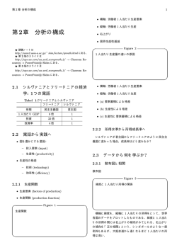
VFB = 300 mV
R1
15 W
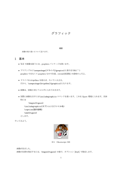
Figure 1. Typical Application Circuit
Table 1. ABSOLUTE MAXIMUM RATINGS
Parameter
Rating
Unit
VIN, FB voltage
−0.3 to +7
V
SHDN voltage
−0.3 to +7
V
SW voltage
−0.3 to +40
V
Storage Temperature Range
−65 to +160
_C
Junction Temperature Range
−40 to +150
_C
300
_C
Lead Temperature
Stresses exceeding Maximum Ratings may damage the device. Maximum Ratings are stress ratings only. Functional operation above the
Recommended Operating Conditions is not implied. Extended exposure to stresses above the Recommended Operating Conditions may affect
device reliability.
Table 2. RECOMMENDED OPERATING CONDITIONS
Parameter
VIN
SW pin voltage
Ambient Temperature Range
LED Bias Current
http://onsemi.com
2
Range
Unit
2.2 to 5.5
V
0 to 24
V
−40 to +85
_C
1 to 30
mA
CAT4137
Table 3. ELECTRICAL OPERATING CHARACTERISTICS
(VIN = 3.6 V, ambient temperature of 25°C (over recommended operating conditions unless otherwise specified))
Symbol
Parameter
Conditions
Min
Typ
Max
Unit
IQ
Operating Current
VFB = 0.3 V
VFB = 0.4 V (not switching)
0.4
0.1
1.5
0.3
mA
ISD
Shutdown Current
VSHDN = 0 V
0.1
1
mA
VFB
FB Pin Voltage
3 LEDs with ILED = 20 mA
300
315
mV
IFB
FB pin input leakage
0.1
1
mA
ILED
Programmed LED Current
28.5
19
14.25
30
20
15
31.5
21
15.75
mA
0.4
0.8
0.7
1.5
V
VIH
VIL
R1 = 10 W
R1 = 15 W
R1 = 20 W
SHDN Logic High
SHDN Logic Low
Enable Threshold Level
Shutdown Threshold Level
285
FSW
Switching Frequency
0.7
1.0
1.3
MHz
ILIM
Switch Current Limit
250
300
400
mA
RSW
Switch “On” Resistance
ISW = 100 mA
1.0
2.0
W
ILEAK
Switch Leakage Current
Switch Off, VSW = 5 V
1
5
mA
TSD
Thermal Shutdown
THYS
Thermal Hysteresis
h
Efficiency
Typical Application Circuit
VUVLO
Undervoltage Lockout (UVLO) Threshold
VOV-SW
Output Clamp Voltage
“Open LED” fault
http://onsemi.com
3
150
°C
20
°C
86
%
1.9
V
29
V
CAT4137
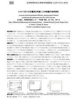
TYPICAL CHARACTERISTICS
(VIN = 3.6 V, CIN = 1.0 mF, COUT = 0.22 mF, L = 22 mH with 3 LEDs at 20 mA, TAMB = 25°C, unless otherwise specified.)
120
1.00
100
SUPPLY CURRENT (mA)
SUPPLY CURRENT (mA)
VFB = 0.4 V
80
60
40
20
0
2.5
3.0
3.5
4.0
4.5
0.75
0.50
0.25
0
5.0
2.5
3.0
3.5
INPUT VOLTAGE (V)
Figure 2. Quiescent Current vs. VIN
(Not Switching)
Figure 3. Quiescent Current vs. VIN
(Switching)
FB PIN VOLTAGE (mV)
FB PIN VOLTAGE (mV)
3 LEDs
305
300
295
2.5
3.0
3.5
4.0
4.5
305
300
295
290
5.0
0
5
10
15
20
25
INPUT VOLTAGE (V)
OUTPUT CURRENT (mA)
Figure 4. FB Pin Voltage vs. Supply Voltage
Figure 5. FB Pin Voltage vs. Output Current
30
2.0
1.10
3 LEDs at 20 mA
SWITCH RESISTANCE (W)
CLOCK FREQUENCY (MHz)
5.0
310
3 LEDs
1.05
1.00
0.95
0.90
4.5
INPUT VOLTAGE (V)
310
290
4.0
2.5
3.0
3.5
4.0
1.5
1.0
0.5
0
4.5
2.5
3.0
3.5
4.0
4.5
INPUT VOLTAGE (V)
INPUT VOLTAGE (V)
Figure 6. Switching Frequency vs. Supply
Voltage
Figure 7. Switch ON Resistance vs.
Input Voltage
http://onsemi.com
4
5.0
CAT4137
TYPICAL CHARACTERISTICS
(VIN = 3.6 V, CIN = 1.0 mF, COUT = 0.22 mF, L = 22 mH with 3 LEDs at 20 mA, TAMB = 25°C, unless otherwise specified.)
35
0.4
LED CURRENT (mA)
30
LED CURRENT VARIATION (%)
RFB = 10 W
25
RFB = 15 W
20
RFB = 20 W
15
10
5
0
2.0
2.5
3.0
3.5
4.0
4.5
3.0
3.5
4.0
4.5
5.0
Figure 9. LED Current Regulation
5.5
100
90
EFFICIENCY (%)
EFFICIENCY (%)
2.5
Figure 8. LED Current vs. Input Voltage
(3 LEDs)
15 mA
20 mA
VIN = 4.2 V
VIN = 3.6 V
80
70
2.0
2.5
3.0
3.5
4.0
4.5
60
5.0
0
5
10
15
20
25
INPUT VOLTAGE (V)
LED CURRENT (mA)
Figure 10. Efficiency across Supply Voltage
(3 LEDs)
Figure 11. Efficiency across Load Current
(3 LEDs)
100
90
90
EFFICIENCY (%)
100
15 mA
80
20 mA
30
VIN = 4.2 V
VIN = 3.6 V
80
70
70
60
2.0
INPUT VOLTAGE (V)
70
EFFICIENCY (%)
−0.2
INPUT VOLTAGE (V)
90
60
0
−0.4
5.0
100
80
0.2
2.0
2.5
3.0
3.5
4.0
4.5
60
5.0
0
5
10
15
20
25
INPUT VOLTAGE (V)
LED CURRENT (mA)
Figure 12. Efficiency across Supply Voltage
(4 LEDs)
Figure 13. Efficiency across Load Current
(4 LEDs)
http://onsemi.com
5
30
CAT4137
TYPICAL CHARACTERISTICS
(VIN = 3.6 V, CIN = 1.0 mF, COUT = 0.22 mF, L = 22 mH with 3 LEDs at 20 mA, TAMB = 25°C, unless otherwise specified.)
1.0
SHUTDOWN VOLTAGE (V)
FB PIN VOLTAGE (mV)
304
302
300
298
3 LEDs at 20 mA
296
294
−50
−25
0
25
50
75
0.4
3.0
3.5
4.0
5.0
4.5
INPUT VOLTAGE (V)
Figure 14. FB Pin Voltage vs. Temperature
Figure 15. Shutdown Voltage vs. Input Voltage
1.10
CLOCK FREQUENCY (MHz)
2.1
2.0
UVLO (V)
85°C
0.6
TEMPERATURE (°C)
2.2
1.9
1.8
1.7
1.6
−50
25°C
0.2
100
−40°C
0.8
−25
0
25
50
75
20 mA per LED
1.05
1.00
0.95
0.90
−50
100
−25
0
25
50
75
TEMPERATURE (°C)
TEMPERATURE (°C)
Figure 16. Under Voltage Lock Out vs.
Temperature
Figure 17. Switching Frequency vs.
Temperature
Figure 18. Switching Waveforms
(3 LEDs in Series)
Figure 19. Switching Waveforms
(2 LEDs in Series)
http://onsemi.com
6
100
CAT4137
TYPICAL CHARACTERISTICS
(VIN = 3.6 V, CIN = 1.0 mF, COUT = 0.22 mF, L = 22 mH with 3 LEDs at 20 mA, TAMB = 25°C, unless otherwise specified.)
Figure 20. Power−up with 3 LEDs at 20 mA
Figure 21. Line Transient Response
(3 V − 5.5 V)
MAX OUTPUT CURRENT (mA)
140
120
VOUT = 10 V
100
80
60
VOUT = 17 V
40
20
0
2.0
2.5
3.0
3.5
4.0
4.5
5.0
INPUT VOLTAGE (V)
Figure 22. Maximum Output Current vs. Input
Voltage
http://onsemi.com
7
5.5
CAT4137
ピン VINは:ロジッ の@?です。デバイスは
2.2 Vから5.5 Vまでの@にしています。デ
バイスの
くでVINピンとGNDピンのに、1 mFの
バイパス・セラミッ ・コンデンサを*+す
ることをします。iロッ アウト (UVLO)
は、@が1.9 Vになるたびに、デバイスをア
イドル・モード(スイッチン をSわない )にします
。
SWピンは:i;<パワー・スイッチのドレイン
・ダイオー
です。インダ タおよびショット
ドのアノードをSWピンに*+するがあります。
SWピンに?るトレースは、ループをAにし、
uなりくするがあります。このピンに
は、24 Vでア ティブになる`が
されています。「オープンLED」フォールトefの
z、デバイスはiVWモードに?り、SWピ
ンは30 Vに ランプされます。
SHDNはシャットダウン・ロジッ の?です。こ
のピンを0.4 Vにすると、デバイスはすぐに
シャットダウン・モードに?り、VWがほぼゼ
ロになります。が1.5 Vのz、デバイスは
にイネーブルされefになります。
FB ピンは0.3 Vでされます。FBピンと
ランドに*+された;<により、¡¢に£って
LEDを=します。
I LED +
GNDは ランドピンです。このピンは PCBの
ランド・プレーンに(**+するがあります。
0.3 V
R1
¤のLEDカソードはFBピンに*+されます。
Table 4. PIN DESCRIPTIONS
Pin #
Name
Function
1
SW
2
GND
Ground pin. Connect the pin to the ground plane.
3
FB
Feedback pin. Connect to the last LED cathode.
4
SHDN
5
VIN
Switch pin. This is the drain of the internal power switch.
Shutdown pin (Logic Low). Set high to enable the driver.
Power Supply input.
http://onsemi.com
8
CAT4137
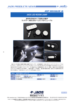
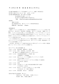
デバイス
CAT4137は、(1 MHz)、iノイズの¦§
7
コンバータで、abにをします。
の:CMOSパワー・スイッチを&'して$
:インダ タを¨wします。パワー・スイッチがタ
ーが$
ーンオフすると、インダ タの©エネル
:ショット ・ダイオードをªしてabに«され
ます。
パワー・スイッチのオン/オフ・デューティ・サイ
ルは、:でIされ、 ピン (FB)に*+され
た$: ;<の®で0.3 Vのを¯°
するように89されます。$:;<±によってLED
バイアス(0.3 V/R1)が²³に=されます。
´µw¶には、:パワー・スイッチのデュー
ティ・サイ ルは、`·な¸?をtし、「ソ
フトスタート」モードを¹するために8さ
れます。
º»¶には、デバイスはAB5qの,-LEDに
AB30 mAのバイアスを¼½できます。
「オープンLED」フォールトefのz、 8
9ループがオープンになるとは
し+け
ます。このが24 Vをhえると、:^_が
ア ティブになり、デバイスはhiVWの
モードに?ります。cえて、: ランピン
はピー を 29 Vに8します。このフ
ォールトefが リアされると、デバイスはx¾
にº»を¿します。
デバイスが150°Cの*z:À4ÁÂ$で
しないようにするために、]`ab^_が
されています。]`abefでは、デバイスはx
¾にシャットダウンし、*z:À4が130°CにÃ
Äされてからº»が¿されます。
VIN
VOUT
SW
C2
C1
1 MHz
Oscillator
300 mV
–
+
Enable
SHDN
Thermal
Shutdown
& UVLO
A1
Driver
+
RC
–
ILED
PWM &
Logic
A2
N1
CC
Current
Sense
RS
GND
–
VREF
+
VIN
Over Voltage
Protection
FB
Figure 23. Block Diagram
http://onsemi.com
9
R1
15 W
CAT4137
アプリケーション
部部の !
ショットキ・ダイオード
CAT4137では、?に1 mF、に0.22 mFの
セラミッ ・コンデンサしかありません。
コンデンサはÅ30 Vがです。º»のe
fでは、1 mFの?コンデンサで¼½です。より
いをとするアプリ ーションには、
2.2 mFや4.7 mFといったよりBきなのコンデンサ
がHしています。À4ÁÂでしているため、
X5RおよびX7Rのコンデンサ・タイプがAHです。
ショット ・ダイオードのÅは、ダイオー
ドをれるピー よりくなければなりませ
ん。ショット ・ダイオードの7は、2で
のÎlでÅがめられています。Aのr
sをÏÐするには、このÎlがuなりi
くなければなりません。ドライバは1 MHzでし
ているためÑgもÆです。B:½のアプリ
ーションには、Central SemiconductorÒのショット
CMDSH2−3 (Å200 mA)またはCMDSH−3 (Å
100 mA)がされます。
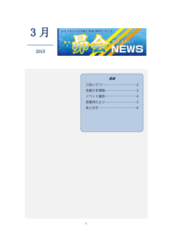
インダクタ
LED電* +
コンデンサ
B:½のCAT4137アプリ ーションには、 22 mHイ
ンダ タがされます。rsがÆなzは、よ
りiい();<を°つインダ タンスがHしていま
す。ÇくのベンダからのÉÊインダ タ・タイプを
&'できます。Figure 24にÉÊインダ タ・タイプ
がabのÁÂにおいて、どのようにrsにËを
ÌえるかをÍします。
LEDは ピン(FB)と ランドの$:;<
で=されます。¡のÓ¢は;<とのÔをÌ
えます。
R1 +
Table 5. RESISTOR R1 AND LED CURRENT
100
3 LEDs
VIN = 3.6 V
LED Current (mA)
R1 (W)
5
60
10
30
15
20
20
15
25
12
30
10
EFFICIENCY (%)
90
80
SUMIDA CDRH3D16−220
MURATA LQH32CN220
PANASONIC ELJ−EA220
PANASONIC ELJ−PC220
70
60
0.3 V
LED current
5
10
15
20
25
30
LED CURRENT (mA)
Figure 24. Efficiency for Various Inductors
http://onsemi.com
10
CAT4137
, -アプリケーション
L
VIN
C1
1 mF
33 mH
C2
SW
VIN
1 mF
100
CAT4137
OFF ON
Aの7をÕるために、2−LEDアプリ ーショ
ンには、33 mHのインダ タと 1 mFのコンデンサ
がされます。
2−LEDÖÐでは、CAT4137には2qのAAアルカリ
×またはLi−ionバッテリから@をできます。
VOUT
SHDN
FB
20 mA
VFB = 300 mV
GND
95
R1
15 W
EFFICIENCY (%)
2.2 V to
5.0 V
D
L: Sumida CDRH3D16−330
D: Central CMDSH2-3 (rated 30 V)
C2: Taiyo Yuden GMK212BJ105KG-T (rated 35 V)
90
VIN = 3.6 V
85
VIN = 3.0 V
80
75
Figure 25. CAT4137 Driving Two LEDs
70
0
10
20
30
LED CURRENT (mA)
Figure 26. Efficiency vs. LED Current, Two LEDs
http://onsemi.com
11
40
CAT4137
./0
LED34の89には、いくつかのÎØがあります。
フィルタされたPWM12
フィルタされたPWMMNは、uRDCとして
LEDの89に&'できます。Figure 29に、
CAT4137のFBピンに*+されたPWM89をÍ
します。PWMMNのåQは0 V〜2.5 Vです。
LEDは0〜22 mAのÁÂでIJできます。PWM
MNは»にiいからA100 kHzのÁ
ÂでRできます。
SHDNピンのPWM12
LED34IJは、PWMMNをSHDN?にÙcし
てSうことができます。LEDはターンオン/ター
ンオフをÚりÛすため、Ü1はデューティ・サ
イ ルにÝÞします。 100%デューティ・サイ ル、
SHDN»gハイは、LEDにßàがれているe
áにâãします。Figure 27および28に、50%デュー
ティ・サイ ルの 1 kHzおよび4kHzMNをSHDNピン
にÙcしたäをÍします。PWMÁÂは
100 Hz〜10 kHzです。PWMÁÂは
100 Hz〜4 kHzです。
VIN
SW
CAT4137
SHDNピンのスイッチング56PWM
2.5 V
PWM
Signal
SHDN
GND
RA
4.02 kW
FB
RB
0V
VFB = 300 mV
R2
1 kW
3.3 kW
C1
0.22 μF
LED
Current
R1
15 W
Figure 29. Circuit for Filtered PWM Signal
0 V DCまたは0%デューティ・サイ ルの PWMM
Nでは、ABLEDは22 mAです。100%デュー
ティ・サイ ルの PWMMNでは、LEDは0 mA
になります。
25
LED CURRENT (mA)
Figure 27. PWM at 1 kHz
20
15
10
5
0
0
20
40
60
80
DUTY CYCLE (%)
Figure 30. LED Current vs. Duty Cycle
Figure 28. PWM at 4 kHz
http://onsemi.com
12
100
CAT4137
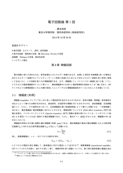
オープンLED=
「オープンLED」フォールトefのz、
CAT4137はが24 VにÏするまで、
をABで
し+けます。が24 Vをhえ
ると、:が(ちにデバイスをhiVWモ
ードに\Sさせ、æ?VWは10 mWçèにな
ります。
iVWモードでは、?はé2 mA
にiします。
L
VIN
は、のを 29 V
: ランピン
に8します。このモードでは、$:^_ツェ
ナー・ダイオードがìです。この^_΢は、デ
バイスを$:ショット ・ダイオードのí (オー
プン)からもに^_します。
(Central CMDSH2−3)
D
V
OUT
22 μH
C1
1 μF
C2
0.22 μF
SW
VIN
CAT4137
OFF ON
SHDN
FB
VFB = 300 mV
GND
R1
15 W
Figure 31. Open LED Protection
Figure 32. Open LED Power−up Waveforms
SUPPLY CURRENT (mA)
2.5
2.0
1.5
1.0
2.5
3.0
4.0
3.5
4.5
INPUT VOLTAGE (V)
Figure 33. Open LED Supply Current vs. VIN
http://onsemi.com
13
5.0
CAT4137
ボード・レイアウト
CAT4137はスイッチン ・レ
ュレータで
す。スイッチン をすトレースは、
EMI、リップル、およびノイズをî¾にïえるた
めに、ボードのレイアウトをñòóくSうがあ
ります。Figure 34にÍすôõは、スイッチン öを÷します。これらすべてのトレースは、øù
インダ タンスとøù;<をAするために、¼
½にくかつQ>くするがあります。Figure 34
にÍすループは、CAT4137の:スイッチがúじて
いるときのöにâãします。Figure35では、
L
D
VIN
VOUT
CAT4137のスイッチがいているときのループ
をÍします。®Îのループともはできるだけ
さくなければなりません。
コンデンサC1はuなりVINピンとGNDの
く
にûüするがあります。コンデンサC2はqýに
トップLEDアノードに*+します。CAT4137のの
ランド・プレーンで、コンデンサを(*
ランド
に*+できます。;<R1はCAT4137のGNDピンに(
**+し、スイッチン ループやそのþの:品
と共'してはなりません。
L
D
VOUT
VIN
SW
SW
VIN
VIN
CAT4137
SHDN
C1
Switch
Closed
CAT4137
FB
SHDN
C2
R1
C1
GND
GND
Figure 34. Closed−switch Current Loop
Switch
Open
FB
C2
Figure 35. Open−switch Current Loop
http://onsemi.com
14
R1
CAT4137
PACKAGE DIMENSIONS
TSOT−23, 5 LEAD
CASE 419AE−01
ISSUE O
SYMBOL
D
MIN
NOM
A1
0.01
0.05
0.10
A2
0.80
0.87
0.90
b
0.30
c
0.12
A
e
E1
1.00
0.45
0.15
D
2.90 BSC
E
2.80 BSC
E1
1.60 BSC
E
MAX
e
0.20
0.95 TYP
L
0.30
0.40
L1
0.60 REF
L2
0.25 BSC
0º
θ
0.50
8º
TOP VIEW
A2 A
b
q
L
A1
c
L2
L1
SIDE VIEW
END VIEW
Notes:
(1) All dimensions are in millimeters. Angles in degrees.
(2) Complies with JEDEC MO-193.
ON Semiconductor and
are registered trademarks of Semiconductor Components Industries, LLC (SCILLC). SCILLC reserves the right to make changes without further notice
to any products herein. SCILLC makes no warranty, representation or guarantee regarding the suitability of its products for any particular purpose, nor does SCILLC assume any liability
arising out of the application or use of any product or circuit, and specifically disclaims any and all liability, including without limitation special, consequential or incidental damages.
“Typical” parameters which may be provided in SCILLC data sheets and/or specifications can and do vary in different applications and actual performance may vary over time. All
operating parameters, including “Typicals” must be validated for each customer application by customer’s technical experts. SCILLC does not convey any license under its patent rights
nor the rights of others. SCILLC products are not designed, intended, or authorized for use as components in systems intended for surgical implant into the body, or other applications
intended to support or sustain life, or for any other application in which the failure of the SCILLC product could create a situation where personal injury or death may occur. Should
Buyer purchase or use SCILLC products for any such unintended or unauthorized application, Buyer shall indemnify and hold SCILLC and its officers, employees, subsidiaries, affiliates,
and distributors harmless against all claims, costs, damages, and expenses, and reasonable attorney fees arising out of, directly or indirectly, any claim of personal injury or death
associated with such unintended or unauthorized use, even if such claim alleges that SCILLC was negligent regarding the design or manufacture of the part. SCILLC is an Equal
Opportunity/Affirmative Action Employer. This literature is subject to all applicable copyright laws and is not for resale in any manner.
PUBLICATION ORDERING INFORMATION
LITERATURE FULFILLMENT:
Literature Distribution Center for ON Semiconductor
P.O. Box 5163, Denver, Colorado 80217 USA
Phone: 303−675−2175 or 800−344−3860 Toll Free USA/Canada
Fax: 303−675−2176 or 800−344−3867 Toll Free USA/Canada
Email: [email protected]
N. American Technical Support: 800−282−9855 Toll Free
USA/Canada
Europe, Middle East and Africa Technical Support:
Phone: 421 33 790 2910
Japan Customer Focus Center
Phone: 81−3−5817−1050
http://onsemi.com
15
ON Semiconductor Website: www.onsemi.com
Order Literature: http://www.onsemi.com/orderlit
For additional information, please contact your local
Sales Representative
CAT4137JP/D
© Copyright 2026 Paperzz