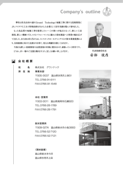
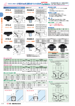
TT02-RWD GRT MODIFIED CHASSIS KIT
TT02-RWD ドリフトカーが遂に登場︕(メカ,ボディ,バッテリー,充電器は別売り)
イーグル開発チームが14か月以上かけて仕上げた、フロントサーボマウント、リア2WDドリフトカーです。計算し尽くされたフロントステアリングシステムは、スムーズなハンドリン
グと高舵角を得ることが出来ました。またメンテナンス性重視のリアパワートレインは、モーターやギア交換等が簡単に行え、ALリアギアボックスは、 加減速時の大きな力に対
してもアソビなくしっかりとギアをホールドします。ドリフトカーで最も重要なポイントであるシャーシウエイトバランスは、3種類のバッテリーに対応し、 トータルで14種類のポジショ
ンが選択でき前後重量バランスを調整することで、ドリフト時のステアリング性能をさらに向上致します。多くのイーグルチームドライバーのフィードバックを結集させた、イーグル
の新しい回答なのです。ドリフト走行をサポートする ジャイロ,4種のバッテリーマウントも標準装備︕今までスピンをしていた車が驚くほど綺麗なドリフト走行を可能します。
Fully optional high-end TT02-RWD DRIFT car version can be perform to enjoy from the entry level to the professional.
We design new front center servo mount, The front steering system calculated exhaustively was able to get smooth handling and
high rudder corner. In addition, Rear Motor high mount minimized drive friction, The gear exchange easily hold the rear power train of
the maintenance, AL rear gearbox performs and holds of a gear bearing without any movement, during the high power acceleration. Adjusting anteroposterior weight balance is the key as an answer given by the development team of eagle, and has been working for
more than 14 months to finish. Including GYRO makes it very stable drift run, carry out the spinning and easy to set up for TT02
RWD
完成図
商品仕様
■ フロントセンターサーボマウント
■ リア 2WD ドリフトカー
■ AL リアギアボックス
■ ドリフト仕様
■ アルミ製足回り
■ ヘリカルギア付き リアソリッドアクスル搭載
■ ハイトアジャスタ―付アルミ製オイルショック
■ 3 種類のバッテリーに対応 ( トータルで 14 種類のポジションが選択可能 )
Specification
■ Front center servo mount
■ AL rear gearbox, and Suspension
■ Rear solid axle deployment with the strong helical gear
■ Selectable by total 14 kinds of battery positions
■ American spur gear adapter
■ Includes GYRO
■ Rear motor high mount
■ Height control shocks 52-55mm
■American 48 pitch spur gear
本説明書をご参照頂き、十分にご理解頂いた上でご使用ください。
また、必要に応じてネジロック剤の使用をお勧め致します。
(#3318 LOCTITE 242ネジロック剤 NET.0,5ml \350)
Screw Lock is need in this chassis.
Please lock the screw before running.
※本説明書の画像はイメージです。
デザインは予告なく変更される場合がございます。
The specification will be change without prior notice.
接
着
剤
本製品はグラファイトを主に使用した製品になっているため、エッジの部分に衝撃が加わるとささくれのようになってしまう場合がございます。
ささくれを未然に防ぐために以下の手順を行ってください。
This Item is mostly made by graphite. when hit the edge of the graphite it will be like a jagger. to avoid
this please read the following.
出荷時に面取り作業は行っておりますがより一層滑らかにするためにシャーシのエッジ
部分を1000番以上のサンドペーパーでこすります。
Plane the edge by No.1000 sand paper then cement it using
Quick Glue.
サンドペーパーをかけた場所に瞬間接着剤を少量つけ、たれないように
気をつけながらのばしていきます。接着剤で固めることでより強くなります。
We recommend to use #1183
#1183
スーパークイックグルー(5-10sec)
¥490
内容物 Parts
GRT アッパーデッキ
GRT Upper Deck Set
(#TT02RWD05
) 1pcs.
フロントナックル
Front Knuckle
(#TT02RWD06)
フロントアッパーデッキマウント
Front Upper Deck Mount
(#TT02RWD11)
1pair
モーターマウント
Motor Mount
(#TT02RWD12)
1pair
AL ロアサスマウント
AL Lower Sus Mount
(#TT02RWD15)
4pcs.
ALステアリングバアー
AL Steering Bar
(#TT02RWD16)
1Set
サーボマウント
Servo Mount
(#TT02RWD17)
アンテナポスト
Antenna Post
(#2239)
リア ディフューザー
Rear Diffuser
R31-16FMP28
1pcs.
GRT メインシャーシ
GRT Main Chassis
(#TT02RWD01 ) 1pcs.
GRT フロントショックタワー
GRT Front Shock Tower
(#TT02RWD02 )
1pcs.
GRT リアショックタワー
GRT Rear Shock Tower
(#TT02RWD03 ) 1pcs.
バンパーセット
Bumper Set
(#TT02RWD04
リアハブ
Rear Hub
(#TT02RWD09)
トー角調整用パーツ
Toe angle adjustment parts
(#R31-05V2B)
1set
リア ロア サスアーム
Rear Lower Susarm
(#TT02RWD10) 1pair
フロントステアリングリンケージ
Front Stearing Linkage
(#TT02RWD13)
1set
ステンレス ・ リアアッパーアーム
AL ギアボックス 2
AL Gear Box 2
(#TT02RWD20)
1pcs.
ショックセット スプリング付
Shock Set w/Spring
(#TT02RWD21)
4pcs.
スパーギアーアダプター
Spar Gear Adapter
(#TT02RWD26)
1set
1pair
Stainless Steel Rear Upper Arm
(#TT02RWD14)
1set
リア ・ ヘリカルソリッドアクスル 16/30T
Rear Helical Solid Axle 16/30T
(#TT02RWD27)
1pcs.
1pcs.
AL ディフューザーマウント
AL Diffuser Mount
(#TT02RWD28 ) 1pcs.
)
1set
ボディ ポスト
Body Post
(#TT02FRD30)each2pcs
フロントロアサスアーム
Front Lower Sus Arm
(#TT02RWD07)
1pair
フロントアッパーアーム
Front Upper Arm
(#TT02RWD08)
ホイールアクス Wheel Axle
(#3711V3P22-WS) 2pcs.
ユニバーサルシャフト
Universal Shaft
(#R31-15-46)
2pcs.
KP 48 ピッチ 7T スパーギア
KP 48pitch 77TSpar Gear
(#1082-77T)
2pcs.
1Set
ステアリングボールベアリングセット
Steering Ball Bearing Set
(#TT02RWD18)
1Set
サーボホーンセット
Servo Horn Set
(#TT02RWD19)
1pcs.
ホイルアダプター 5.0mm
Wheel Adapter 5.0mm
(#3905-50)
1set
GRT バッテリーホルダー A
GRT Battery Holder A
(#TT02RWD22)
1set
GRT バッテリーホルダー B
GRT Battery Holder B
(#TT02RWD23)
1set
GRT バッテリーホルダー C
GRT Battery Holder C
(#TT02RWD24)
1set
GRT バッテリーホルダー D
GRT Battery Holder D
(#TT02RWD25)
1set
ホイールタイヤセット
Wheel & Tire
4set
ジャイロ
Jyro
(#3944)
1pair
1pair
1pcs.
オプション Option
AKC ステアリングセット
AKC Steering Bar
(#TT02RWD29)
1Set.
GRT ウエイトセット
GRT Weight Set
(#TT02FRD25)
1Set.
GRT ウエイトセット
GRT Weight Set
(#TT02FRD25A)
1Set.
M5.5X0.2 スペーサー
M5.5X0.2 Spacer
ホイルナット
Wheel Nut
(3924-1LBL)
M3x6 ナベビス
M3x6 Button Screw
4pcs.
8pcs.
M4.8 ボールナットスクリュー
M4.8Ball Nut Screw
2pcs.
M3 ナット
M3 Nut
M3x8 ナベビス
M3x8 Button Screw
M4.8 ボールスクリュー
M4.8Ball Screw
6pcs.
7pcs.
4pcs.
2pcs.
M6X1 スペーサー
M6X1 Spacer
4pcs.
M7X1 スペーサー
M7X1 Spacer
M3x6 皿ビス
M3x6 Flat Head Screw
23pcs.
M3x8 皿ビス
M3x8 Flat Head Screw
16pcs.
M3x10 皿ビス
M3x10 Flat Head Screw
10pcs.
M3x12 皿ビス
M3x12 Flat Head Screw
2pcs.
M3x20 皿ビス
M3x20 Flat Head Screw
2pcs.
M5X6 スペーサー
M5X6 Spacer
M3x10 ナベビス
M3x10 Button Screw
10pcs.
M3x12 ナベビス
M3x12 Button Screw
M3x18 ナベビス
M3x18 Button Screw
M3x5 イモネジ
M3x5 Set Screw
M3x10 イモネジ
M3x10 Set Screw
M3x16 イモネジ
M3x16 Set Screw
M4.8 ボールスタッド
M4.8 Ball Stud
M3 皿ワッシャー
M3 Dish Washer
8pcs.
2pcs.
6 pcs.
M3X5X1 O リング
M3X5X1 ORing
4pcs.
8pcs.
1510 ベアリング
1510 Bearing
2pcs.
4pcs.
1050 ベアリング
1050Bearing
2pcs.
4pcs.
840 ベアリング
840Bearing
12pcs.
8pcs.
4pcs.
4pcs.
STEP01 : フロントナックルとロアアームの組立/Assembly Front Arms
1.図は基本設定となっています。エンドボールの取付位置を変更することでステアリング特性を変更することが出来ます。
組立後は、 シャーシへアッパーリンケージとタイロッドの長さに注意して取付けます。 ピロボールを取り付けを変更することで、 操作性を変更することが出来ます。
また、 ロアアームにある M3X10 イモネジの締め具合でシャーシの地上高を調整することが出来ます。 After Assemble, install it to the chassis with the upper arm and linkage.
You may change other setting using other hole position.The chassis height can be adjust by using M3X10 set screw.
M5.7
ベアリング
エンドボール
BB 1510
AL スペーサー
キャップスクリュー
Shim 6X1
Screw M3X14
ベアリング
BB 1050
ピン
2X10
キャップスクリュー
Screw M2.0X5
Shim 6X1
セットスクリュー
Screw M3X16
AL スペーサー
Shim 5X6
AL スペーサー
M5.7
エンドボール
STEP02 : フロントロアアームの取付
/Mounting Front Arms
AL スペーサー
Shim 5X12.5
2.図は基本設定となっています。(アッパーサスシャフトと対象的にAL
スペーサーを移動させると大きなキャンバーが付きます。)
厚みの異なるサスピン・スペーサーを取り付けることで、ホイルベース&キャスターを調整
することが出来ます。
Figure has become the basic settings, As opposed to move aluminum spacer
with large camber and turnbuckles shaft, You can adjust the wheelbase
casters, by installing different thickness of the pin spacer.
AL スペーサー
Shim 5.5X1
AL スペーサー
Shim 5X8.5
皿ビス
Screw M3X6
皿ビス
皿ビス
Screw M3X6
Screw M3X6
STEP03 : フロント/ステアリングバーの組立 /Assembly Front Steering Bar
3.図のように組み立て、センターステアリングバーがガタなくスムーズに動くのを確認してください。
エンドボール
M4.8
Make sure that the Front steering bar is smooth and without clearance,
Assembly as shown in the figure.
ベアリング
BB 8X4
皿ワッシャー
Shim 6.3X1.8
ナベビス
Screw M3X6
皿ビス
Screw M3X8
皿ビス
Screw M3X8
皿ワッシャー
Shim 6.3X1.8
BB 8X4
ベアリング
STEP04 : ボディマウントとフロントアッパーアームの組立
/Assembly Front Arms & Body Mount
ナベビス
4.図は基本設定となっています。サスシャフトのALスペーサーの位置を変更することでキャスターを変更することが
出来ます。(ロアサスシャフトと対象的にALスペーサーを移動させると大きなキャスターが付きます。)
The figure becomes the basic setting. You can change a caster by changing the position
Shim 6.5X4.8
of the AL spacer of the shaft.
①キットには、3種類のボディマウントが付属しております。用途によってお好みの物をお選びください。 AL スペーサーShim 5.5X0.2
Shim 7X1
②またイーグルでは多くの種類のステルスボディーマウントを取り揃えています。
これらを使う事でよりスケール感を重視るす事が出来ます。
(1) Three types of body Mount included in the kit.You can choose body
mount depending on your style (2) also, we recommend reasonable
AL スペーサー
Shim 7X1
price with Eagle body mount stealth.
Screw M3X10
Shim 5.5X0.2
AL スペーサー
Shim 7X1
Shim 7X1
AL スペーサー
M3 皿ワッシャー
ナベビス
Screw M3X10
Screw M3X10
皿ビス
M3×10mm 皿ビス
STEP05 : サーボの組立/Mounting Servo
5.このキットに取付可能なサーボは、以下のサイズの物のみとなります。上側のサーボマウントは、予めシャーシ側に仮止めしておきます。下側のサーボマウントは
サーボに取付た後、以下の図の順番でシャーシに取付けます。
注意︔次にサーボアームとアームプレートのセンターステアリングバーへの取付は、ステアリングがニュートラル位置で7.5X6mmスペーサーがアームプレートの長穴の
下側になっているかを確認してください。
The following type of servo sizes which can be attach to this kit. The servo mount of the upper part performs
a temporary end in the chassis side. Bottom servo mounts are mounted, and then installs it on the chassis as shown below.
Note: Mounting the servo and the arm plate Center steering bar into neutral position.
Please see the 7.6X6mm spacer is in the under of the long holes of the arm plate.
ナベビス
M3X12
ブラストスペーサー
ナベビス
M3X6
ナベビス
Screw M3X6
ブラストスペーサー
Collar 7.5X6
ナベビス
Screw M3X12
ブラストスペーサー
Collar 7.5X8
ナベビス
Screw M3X12
皿ビス
Screw M3X6
STEP06 : ショックの組立とフロントショックの取付
/Assembly Shocks
スペーサー Spacer
6.5X2.3
ショックボディ
Shock Body
8.5X1.5
O リング
52-55mm
ハイトアジャスター機能付ショックは、オイルを入れショックキャップをしめた後、
ショックエンドを回転させることで、ショック使用範囲の長さを52-55mm
Oing 13X1.5
で変更が可能です。お好みの長さに調整してお使いください。
O リング
Shock wrench included into this kit.
ショックエンド
Oing 9X1.5
Shock End
This shock height adjuster function possible to
change at 52-55mm by the length of the shock M3 Eリング
ショックキャップ
use range, After put oil occupied cap closed
Shock Cap
by turning the shock end.
ショックレンチ
ピストン
Shock Wrench
Adjust it to your preferred
Piston
length Assembly as shown
ピストンシャフト
O リング
注意︓
in figure.
Piston Shaft
上記設定でピストンシャフトの動きが重い場合、 6.5X2.3(4pcs)デルリンスペーサーの
代わりに 6.5X1.5(4pcs)デルリンスペーサーお使いください。
If the movement of the piston shaft is tight in the above setting,
Please use 6.5X1.5 (4pcs) Delrin spacer instead of 6.5X2.3 (4pcs) Delrin spacer.
ショックボディエンド
Shock Body End
テンションダイヤル
Tension Dial
スプリングストッパー
Spring Stopper
スプリング
Spring
ナイロンナット
Lockunt M3
ボールエンド
Ball End
■ オイル注入方法
① まず初めに、 ボールエンドの上部にあるジュラ製スプリングストッパーをスライドさせ取り外します。
② 次にスプリングを取り外します。
③ ショックボディを片方の指で押さえ、 ショックエンドとショックキャップを取り外します。
④ ショックボディを固定し、 お好みのシリコン・オイルを注入します。
⑤ シャフトを幾度か上下させ、 オイル内に入っている気泡を取り除きます。
O リング
時間をかけて完全に気泡を取り除くには
M3X5X1 Oing
#1259 ダンパースタンド \380(別売)などを使用すると大変便利です。
⑥ 空気が抜けて減った分のオイルを再度継ぎ足します。
ナベビス
⑦ ショックボディ内部へ空気が入らないように気を付け、 ショックキャップとショックエンドを取り付けます。
Screw M3X18
⑧ スプリングとジュラ製スプリングストッパーを元通りに戻し完成です。
⑨最後にショックエンドの締め具合をお好みの 52-55mmの範囲で調整してください。
■ セットアップ
ダンパースプリング … グリーン︓1.3mmソフト , ライトブルー︓1.2mm スーパーソフト , ブルー︓1.1mm
エクストラソフトの 3 種類が付属されています。
ピストンは、 出荷時に 3 穴が組込まれています。 1 又は 2 穴は別売の物をお求めください。
AL スペーサー
Shim 5X6
SETUP: Three different types of damper spring are included:
Green:1.3mm Soft, Light Blue:1.2mm Super Soft, Blue:1.1 mm Extra Soft.
Piston come with 3 holes built in at the factory. available 1 and 2 holes for option.
STEP07: リアアクスルの組立/Assembly Rear Axle
このキットには48ピッチ77Tスパーが入っております。スパーギア取付には2また3本の3X8mmナベビスを用い、スパーギアプレート、スパーギア、スパーギアアダプターの順で
固定します。
注意︓スパーギアの交換際は、アッパーデッキを固定している6か所のビスを取外し、次にリアアッパーデッキマウントの下の2本のビスを外し前側にスライドさせ取外し交換します。
REAR AXLE ASSEMBLING:
77T 48 pitch spur gear is included in this kit. to mount spur gear use two or three 3X8mm head screw
then fix spur gear plate and adapter.
Note: Remove the 6 screw that secures the upper deck change the spur gear, unscrew the bottom two screws in the rear upper deck
mount, slide the front then remove and replace.
① ギアボックスの下半分をシャーシへ取付けます。
② プロペラジョイントを、図のようにホルダー側から挿しこみベベルギアを固定します。
③ ギアボックスの中へ、向きに注意しながらソリッドアクスルを入れ、両サイドのベアリング
をギアボックスにはめ込み、ギアへシリコンルブ等の注油を行います。
④ ギアボックスの上半分をはめ、ビスで固定します。この際、ギアクリアランス調整の必要
な場合は別売のシムで調整を行ってください。
⑤ スパーギアを固定する際は。3X8ナベビスを2または3本で固定してください。
⑥ 図の順番でその他部品も固定します。
ナベビス
Screw M3X8
ベアリング
BB 11X4
ナベビス
Screw M3X8(2or3PCS)
ピン
Pin 2X8
AL スペーサー
Shim 7.5X2
① Install the lower half part of the gearbox into the chassis.
② Install the bevel gear into the propeller joint with the other
parts as shown in the drawing .
③ Put the solid axle to the gear box, then covered with upper
gear box cover while paying attention.
④ IF you need, the gear clearance adjustment, please adjust it
with shim available separate sale.
⑤ Use 2 or 3 Pcs of 3X8mm button screw when sper gear hold.
⑥ continuer to assembling other parts too.
BB 11X4
ベアリング
皿ビス
Screw M3X8
皿ビス
Screw M3X8
STEP08 : リアアームの組立
/Assembly Rear Arms
組立後は、 ユニバーサルジョイントと共にシャーシ本体に取付けてください。
シャーシに取付け後、 アッパーリンクの長さに注意して取付けます。 お好みの位置にピ
ロボールを取り付け、 ボールエンドをはめ込んでください。 また、 ロアアームにある
M3X10 イモネジの締め具合でシャーシの地上高を調整することが出来ます。
After Assemble, install it with Universal Joint then insert the upper
link.The chassis height can be adjust by using M3X10 set screw.
1510 ボールベアリング
M4.8 ボールナットスクリュー
リアハブのサスピンを通す部分に、トーコントロール用のパーツがはめ込んであります。
このパーツを付属の物と交換することで、0,1,2度の3つの角度からトーイン調整をすることができ
ます。
トー角調整用パーツ
1050 ボールベアリング
You can change the Toe angle choosing Rear suspension pin bushing.
M3x10 イモネジ
M3x3 イモネジ
トー角 Toe 0°
トー角 Toe 2°
トー角 Toe 1°
STEP09 : リアアームの組立
/Mounting Rear Arms
AL スペーサー
Shim 5X10.5
図は基本設定となっています。厚みの異なるサスピン・スペーサーを
取り付けることで、ホイルベースを調整することが出来ます。
The wheel base can be adjust by using diffrent size of
suspension pin spacer.
Shim 5.5X2
AL スペーサー
Shim 5X7.5
皿ビス
Screw M3X6
STEP10 : リアショックの取り付け/Mounting Rear Shocks
図は基本設定となっています。取付位置を変更することでサスワークを変更することが出来ます。
This drawing is basic setting. You may choose different set up position assembly as shown in the figure.
①キットには、3種類のボディマウントが付属しております。用途によってお好みの物をお選びください。
②またイーグルでは多くの種類のステルスボディーマウントを取り揃えています。
これらを使う事でよりスケール感を重視るす事が出来ます。
エンドボール
(1) Three types of body Mount included in the kit.You can choose body
M4.8
mount depends on your style (2) also, we recommend reasonable
ナベビス
price with Eagle body mount stealth.
Screw M3X8
ボールスタッド
M4.8
スペーサー
セットスクリュー ALShim
5X6
Screw M3X16
O リング
M3X5X1 Oing
ナベビス
Screw M3X6
M3 皿ワッシャー
Shim 8X0.6
AL スペーサー
O リング
O ring 5X1
ナベビス
Screw M3X18
Shim 5X6
AL スペーサー
M4.8
ボールスタッド
M3×10mm 皿ビス
Screw M3X16
セットスクリュー
ナイロンナット
Lock nut M3
STEP11 :バンパーの組立/Mounting Front Bumper 図を参考にフ ロントバンパーを正しく取付けてください。
Please assemble front bumper properly as shown in the figure.
皿ネジ
Screw M3X6
ナイロンナット
Locknut M3
皿ネジ
Screw M3X6
皿ネジ
Screw M3X8
STEP12 : リアディフューザーの組立/Mounting Rear Diffuser
① AL ディフュザーマウントをシャーシに取付けます。
② シャーシとAL ディフュザーマウントの間にリアディフュザーを押し込み、上部にウエイトプ
レートのせビスで固定します。
① Install AL diffuser mount into the chassis.
② Install rear diffuser between the chassis and AL diffuser
mount then hold by screw.
皿ネジ
皿ネジ
皿ネジ
STEP13 : アッパーデッキとバッテリーマウントの組立
/Mounting Upper Deck
皿ネジ
Screw M3X20
メインシャーシに、アッパーデッキを取り付けます。厚みのあるESCなどをシャーシと
メカデッキの間に装着する場合は、必要に応じて6.4mmスペーサー(図の
皿ネジ
赤い部分6ヶ所)を挟みこみます。その際スペーサー付属の長ネジに
Screw M3X12
交換してください。
Install upper deck into the chassis as shown in the figure.
As per the height lenght desired, you may use 6X6.4 shim (6pcs), in between the chassis and upper deck , suitable
for bulky ESC. During the replacement of the screw,
you may need a little more longer than the
previous used screw,so we attached
long screw ( M3x16 4pcs)+ (M3x28 2pcs)
AL スペーサー
with 6x6.4 shim 6 pcs in one pack. Shim 6X6.4
AL スペーサー
Shim 6X2
皿ネジ
Screw M3X10
皿ネジ
Screw M3X6
皿ネジ
Screw M3X8 M3 Dish Washer
M3 皿ワッシャー
AL スペーサー
Shim 6X7
AL スペーサー
Shim 6X6.4
STEP14 : バッテリーマウントの取付/Mounting Battery Mount
メインシャーシに、バッテリーホルダーを取り付けます。
3種類のバッテリーに対応し、 トータルで14種類のポジションが選択でき前後重量バランスを調整することで、ドリフト時のステアリング性能をさらに向上致します。
Chassis weight balance is the most important point copes with three kinds of battery by drift car and improves steering
performance more at the time of the drift by being able to choose 14 kinds of positions.
GRT バッテリーホルダー
GRT Battery Holder
(#TT02RWD22)
1set
GRT バッテリーホルダー
GRT Battery Holder
(#TT02RWD23)
1set
GRT バッテリーホルダー
GRT Battery Holder
(#TT02RWD24)
1set
GRT バッテリーホルダー
GRT Battery Holder
(#TT02RWD25)
1set
STEP15 : モーターの取付
/Mounting Motor
ピニオン設定
本キットのソリッドアクスルには、16T/30T のヘリカルギアが使われており
ます。また、付属のスパーギアは 48 ピッチ 77T です。
使用される路面や気温、タイヤのコンパウンドでモーターへの負担は大きく
変化します。始めのピニオン選択には、十分注意が必要です。
もしも、お使いのモーターが 10.5 ブラシレスモーターならば 22 から 24T 前後
のピニオンギアからお勧め致します。その使用環境で ESC とモーターへの過度
な負担が無ければ、少しずつ大きな歯数の物に交換してください。
最初のテスト時は、ESC とモーターの温度を15秒毎に監視してください。
それぞれ 70°C 以上にならない様にし、過度の発熱がある場合は、ピニオン
ギアを小さいものに交換してください。
Pinion Setting
This kit has already with 16T / 30T solid axle and 48 pitch 77T spur gear.
The motor current will change it depends on the tracks surface ,air temperature
and tire compound.Please becareful in choosing the kind of 48 pitch pinion you
may use. If you try to test the 10.5 brushless motor, we suggest to use from
22 to 24 teeth pinion gear.
During the first test , please monitor the temperature of the ESC and motor every 15 seconds .
if there is excessive heat more than 70 ° C, you must change into small pinion gear.
But if there is no excessive heat more than 70 ° C, you can change into higher pinion gear
step by step.
STEP16 : ホイルの取付/Mounting Wheels
タイヤホイルの取付け、フロントとリアのアクスルにM2ピンを通し、六角ハブ、
ホイルの順でナイロンナットで固定します。
Mounting the wheels into the chassis as shown in the figure.
2X9.7mm ピン
M2X4.5 キャップビス
M4 ホイルナット
5mm ホイルアダプター
STEP17: メカの組込/Mounting ESC & RX
バッテリーの形状とポジションによって異なりますが、シャーシとアッパーデッキのあいている場所に、
バランスよくESCとレシーバーを装着してください。
Equipped and replace the ESC and receiver depending on the shape
of the battery position and balanced.
STEP018 : ジャイロの搭載 ジャイロの搭載 / Mounting Gyro
図を参考にして、アッパーデッキ後部のAまたはBにジャイロを両面テープで固定します。
Mounting Gyro on the back side of upper deck. See figure and check the direction of Gyro either A or B.
A
B
別売ウエイトプレートの組立
Optional Rear Diffuser Weight Plate
① AL ディフュザーマウントをシャーシに取付けます。
② シャーシとAL ディフュザーマウントの間にリアディフュザーを押し込み、上部にウエイトプ
レートのせビスで固定します。
③ キットには5gのウエイトが5個付属しています。必要に応じてウエイトをウエイトプレー
トに固定してください。
④ 別売のウエイトを購入っすることで、さらに5gのウエイトが5個追加装着することが出
来ます。 その場合M3X10のセットスクリューを用いてウエイトプレートに固定します。
① Install AL diffuser mount into the chassis.
② Install rear diffuser between the chassis and AL diffuser
mount then fix with the weight plate.
③ 5pcs of 5g weight in this kit. Please fix weight on a weight plate as
you need.
④ You can buy additional 5pcs of 5g in case you need more heavy.
Fix on weight plate using a set screw of M3X10.
M3X8 皿ビス
M3X6 ナベビス
ウエイトプレート
5gウエイト
AL ディフュザーマウント
M3X8 皿ビス
ディフュザー
5g
5g
5g
5g
5g
5g
5g
5g
5g
5g
製品保証
譲渡・転売・中古販売・個人オークション等にて入手された製品は弊社保証対象外となります。あくまでも、イーグル販売特約店又は、イーグルホームページから直接購入の製品が保証対象となります。
製品に材料や部品、組み立てに欠陥がある場合に対し商品購入から3ヶ月以内にお問い合わせいただければ保証対応させていただきます。(保証対応には購入日のわかるレシートが必要です。大切
に保管してください。)
間違った設置・接続、部品の使用劣化、内部機器の温度や過度の衝撃が加わったことによる回路基板の故障、水分や湿気にさらしたことによる故障、回路のショート、いかなる衝撃・浸水・天災による
故障、は保証の範囲外です。
この製品の使用についてイーグルは、この製品の使用から生じるいかなる損害の責任も負いません。
全ての製品は出荷される前に工場内で十分に品質検査されたものです。それゆえ、正常に作動すると考えられます。本品を接続し使用することは、ユーザーは使用から生ずる全ての損害に対しての賠
償責任を負うことを承認したことになります。どのような場合にも、その製品の原価を超える賠償責任を負いません。
株式会社イーグル模型は、本品と、その他関連電子機器の使用を管理できないため、本品を使用して生じた、いかなる対人対物事故とそれに伴う損害、損失に対し一切の賠償責任を負いません。
株式会社イーグル模型は予告なしに保証規定を修正する権利を有します。製品にお気づきの点がございましたら走行前にご連絡ください。
製品保証に付いての注意事項とアフターサービス
・社外品との使用やコード交換等の製品にダメージを与える恐れのある改造がある場合は、保証対象外となります。
・修理サービスにつきましては、イーグル・サービスカウンターで行っていますのでお問い合わせください。
・製品保証につきましては、弊社保証規定に準じた対応をさせて頂きます。
保証依頼の場合は購入時のレシート又は、イーグル製品特約店様での購入日の分かる購入の控えが必ず必要になります。
大切に保管して下さい。(これらが無い物は保証の対象外となります。)
・本品や本説明書は事前の予告無く仕様を変更する場合があります。ご了承ください。
IMPORTANT :
① To avoid personal injury, Be careful when using tools.
② Disconnect all the battery when the kit is not in use.
③ Please donʼ t use this kit on the road that will cause of vehicle traffic.
④ Keep out of reach of children under 14 years old.
⑤ You must immediately disconnect all the electronic parts such as heatsink,PC board may be hot and might cause of burns.
〒440-0842 愛知県豊橋市岩屋町62-79
☆その他、ご質問等がございましたらお気軽にお問い合わせください。
☆イーグル・サービスカウンター : [email protected]
© Copyright 2026 Paperzz