DDK0668T
6-ch FET H-Bridge モータコントロールボード
型名 6 Channel Motor Controller Board
ユーザーガイド
2008.01.12
Overview
Features 特長
各チャンネル連続2Aドライブ可能
12ⅤまでのDCモータに使用できます。
6チャンネル個別のスピード制御
PWM制御・最大周波数1.92kHz
USART(シリアル)通信
9600、19200、38400、57600、115200
I²C 通信インターフェイス装備(100kHzまたは400kHz)
Description 概要
この6chモータコントロールボードは6個までのDCモータをそれぞれ個別にスピ
ード制御できるもので、車輪走行の小型のロボット用に開発されましたが、もちろん他
のいろんな用途での使用もできます。
この6chモータコントロールボードは弊社ロボットTJ2使用のプログラム
「C-Style」で使えるように設計されていますが、I²C、または USART(シリアル)通信で
簡単に使用して頂けます。
Absolute Maximum Ratings 絶対最大定格
下記絶対最大定格を超えるストレスを加えると、ボード上のディバイスに恒久的な損傷を与え
ることがあります。また、絶対最大定格は条件内であっても長時間の使用を規定するものでは
ありません。使用に当っては下記の推奨操作範囲での使用をお勧めします。
モータ電圧 (VMOT)
コントロール端子電圧
モータ電流
- 0.3V to +20.0V
- 0.3V to +5.5V
12A continuous (2A/channel)
Recommended Operational Ratings
推奨操作範囲
モータ電圧 (VMOT)
コントロール端子電圧
モータ電流
+3.0V to +12.0V
+4.5 to +5.5V
0 to 6A continuous (1A/channel)
1
Device Details
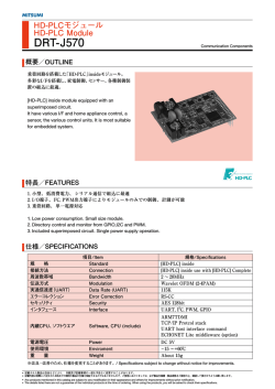
This board is controlled by a PIC18F2431 microcontroller, which controls both the
PWM and communication signals.
There are three (3) PWM controlled FET H-bridge motor outputs on each side of the
PCB. Motors 1, 3 and 5 are on the left, and motors 2, 4, 6 are on the right. Each side
can drive up to 3A total current and each motor can drive up to 2A each. So 2A max
for one motor, 1.75A each for two motors and 1A each for 3 motors per side. Two
LED’s are paired with each motor output to indicate the “direction” of the motor, either
forward (green) or reverse (red).
Top View
モータ出力 2,4,6
モータ出力 1,3,5
PIC18F2431
マイコン
USART(シリアル)
通信コネクタ
I²C 通信
コネクタ
2
At the bottom of the board are three connectors, two on top and one on the bottom.
The blue connector is for I²C communication and the black one is for USART, which
can be modified to 232C level for PC communication. The red connector on the
bottom is the motor power supply. Any DC voltage between +0 and +12V can be
supplied here. A more detailed description of some of the features of these connectors
will follow in the next section.
Bottom View
モータ電源
コネクタ
3
Motor Connections
The red connector marked “Motor
Power” provides voltage (0 to
+12VDC) to only the motors. The
CPU is powered separately through
the I²C connection. The diodes
protect the circuit from over-current
and reverse voltage.
Please take care to use the
correct polarity and not to drive
current or connect voltage over
the maximum recommended
levels.
Control Connections
Serial Port
The black 4-pin connector on the 6-channel
motor controller board is the serial interface.
The standard level is TTL, and can be
connected directly to another PIC (or
micro-controller). By using a level converter,
you can connect the board to a PC and can
use the included software. Details about
controlling via the serial connection are found
in the user guide for the PC software.
Pin Assignment
Pin 1 - RX
Pin 2 - +5VDC
Pin 3 - TX
Pin 4 - GND
4
Control Connections Cont’d
I²C Port
The blue 4-pin connector should be
connected to a Master Controller, which
would provide +5VDC, ground, data and clock
for both the Master and the Slave. Sample
Master software for the Microchip PIC18F
series is included on the CD; however, I²C is
compatible with many micro-controllers. Make
sure when connecting, to have the correct
pins matched as shown on the PCB.
Pin Assignment
Pin 1 - SCL
Pin 2 - +5VDC
Pin 3 - SDA
Pin 4 - GND
Controlling the Motors
The motors are controlled using a 1.92 kHz PWM signal. The data to determine the speed
and direction of the motors is received from the Master through the I²C bus. The total
transmitted data is 6 bytes, plus the address byte.
The MSB of each byte indicates the direction of the motor. A “0” in the MSB would move
the motor in a forward direction, while a “1” would move the motor in the reverse direction.
The 7 LSB’s determine the speed (duty) of the motor (PWM output) from 0 to 100%.
(Note: any value over 100 or less than 0, will default the motor to 0% duty and the OFF
state)
The I²C Master should always send 6 bytes to the Slave, even if only one motor is used or
changed, because the order in which the data is received determines motor
number/speed/direction. A brief explanation of I²C will follow later.
5
Using C-Style
If you are using Top Junior 3 or Orca Junior 2, or another compatible ROBOSiTE
robot, just connect the “I2C” port on your robot to the “I2C” port on the motor controller
board. Then, you can easily control the motors using C-Style for TJ3/OJ2.
After installing/updating your C-Style, the window will look the same as pictured
below. It should not be different from the previous C-Style (depends on version). You
can also download the newest C-Style versions from our homepage at
http://www.daisendenshi.com/
6
Using C-Style (Cont’d)
Click on the “Options” tab at the top of the C-Style window and a drop-down menu will
appear as shown in the picture to the right.
Select “Use PWM Mode” using either your mouse or by pressing the “P” key on your
PC keyboard.
7
Using C-Style (Cont’d)
A new “PWM-6” icon should appear in the upper right-hand area of the icon window.
Also, the usual motor icon should have changed to a “PWM-2” icon. Your C-Style
should now look as it does below (depends on version).
8
Using C-Style (Cont’d)
Now, let’s place the “PWM-6” icon in the main window. If you don’t know how to do
this, please check the C-Style manual, also included in the CD.
The PWM control window should pop up, as seen below. From this window, you can
set all 6 PWM outputs to be transmitted to the motor controller board. If you don’t
want to change a motor’s previous settings, deselect the “Modify” check box. (Note:
6 bytes will still be transmitted, just using the previous data. Also, care should be
taken as to what the previous settings were)
9
Using C-Style (Cont’d)
Above is a larger image of the control window. By default, all of the “Modify” boxes
are checked and the PWM’s are set at 50% duty. To change the PWM duty, click the
arrows up or down (Double-arrow is 10% and the single-arrow is 1%) or use the
slide bar directly.
Now, let’s change some of the settings as pictured above. First, deselect the PWM
OUT 6. You will see that the control bar disappears. Remember, the previous
PWM settings will be sent, not the stop command. Slide the PWM OUT 1 bar all
the way to the top or click the double-arrow until it reaches the top. It should now
read 100%. Keep PWM OUT 2 at 50% but select the “Rev.” box. Do the same for
PWM OUT 4 to reverse the direction of the +V and GND. (Caution: Use reverse
only for motors and similar hardware. Reversing the polarity in regular circuits can
cause serious damage and/or injury!). Drag the slide bar on PWM OUT 3 all the
way down or click the double-arrow until it reaches 0%. When your window looks
like the one above, click “OK”.
10
Using C-Style (Cont’d)
Your C-Style window should look as it does above. The PWM duties are listed from
left to right (1-6). For unmodified duties a (***) will appear.
That’s all there is to it!
11
Using the Serial (USART) Port
If you are planning to control the DDK0668 from another microcontroller directly, no level
converter is needed. But, to use the included PC Tool, the USART must be converted to
RS-232C level. The ddkit0507 or ddkit0704 can be used for this purpose.
How to use the 6Ch MCB Tool. First, download the most recent version from
http://robosite.jp then copy the “ROBOSiTE_MCB_Tool.exe” file to
“C:¥Program Files¥Daisen¥ROBOSiTE MCBTool¥” on your PC, as shown below.
12
Once you have copied the file, it’s ready to be used. Just double click on the icon. (You
may want to make a shortcut on your desktop.)
After opening the tool, you should see a window similar to the one above. Please make
sure to have to most recent version.
The control window is quite similar to the dialog window in C-Style. The 2 extra buttons
are “Output On” and “Output Off”.
There are three ways to send the signal to your DDK0668. First, while the “Output Off” is
selected, set the slidebars to your desired settings. Then click the “Output On” button to
send the data. This method should be familiar if you have used C-Style before.
Second, while the “Output On” is selected, you can click the arrows or the slidebars
directly to control your motors in real-time. When “Output Off” is selected again, the Tool
sends the stop signal to all the motors and disables the real-time output of the slidebars.
Third, using the “Text Send” command, you can enter the text directly. Using this method,
you could create a script and run it from any terminal program. The pattern is as follows:
Ex. 1F010:2R030:3F050:4R070:5F090:6R100 then click the “Text Send” button.
In the example above, Motor 1 is 10% forward, Motor 2 is 30% reverse, Motor 3 is 50%
forward, Motor 4 is 70% reverse, Motor 5 is 90% forward and Motor 6 is 100% reverse.
13
All 6 sets need not be sent all at once as in the I2C case. If you only wish to modify
Motor 3, then 3F050 only can be sent. Also, the “:” is not necessary, except only to be
more readable. (Ex. 1F0102R0303F0504R0705F0906R100).
Upgrading DDK0668
Using the serial connection, you can update the firmware for your DDK0668. Connect
the board as usual, and then double-click in the bottom area of the main window. Then
“Update” will appear in the bottom corner.
You can now access the “Firmware Update” option in the “File” Menu.
Click “Firmware Update” and follow the instructions to download the new firmware.
For a detailed description of the UART Port, please refer to the Microchip homepage
(http://www.microchip.com).
14
Using I²C Directly
For a detailed description of the I²C Bus, please refer to the Microchip homepage
(http://www.microchip.com).
A sample code for I²C is included on the CD for Microchip PIC18F devices and
compatible. The included sample is setup to run at 400kHz, although DDK0668 can also
run at 100kHz. With only a few adjustments, you can easily add it into your code and
have direct control over the PWM output on the DDK0668 from your Master CPU. The
default address of the DDK0668 is 0x14.
First, make sure to have the proper references to D_I2C.c and D_I2C.h in your build
area and #include part of your code. You could also copy and paste the variables,
constants, prototypes and functions directly into your code.
Then add the line:
i2c_init();
somewhere in your initialize routine, or at the start of your main(); loop.
You will also need to set some registers needed for I²C to work properly, as well as an
interrupt to take care of the bit clearing that needs to be done. Add the following code
into your initialize routine:
// Enable interrupt priority
RCONbits.IPEN = 1;
// Enable all high priority interrupts
INTCONbits.GIEH = 1;
And then add the following in your function area to handle the SSPIF bit clearing:
////////////////////////////////////////////////////////////////
// high_interrupt routine
void high_handler (void){
//I2C
if (PIR1bits.SSPIF) {
PIR1bits.SSPIF = 0;
}
}
#pragma code high_interrupt = 0x0008
void high_int(void){
_asm goto high_handler _endasm
}
#pragma code
#pragma interrupt high_handler
////////////////////////////////////////////////////////////////
If you already have a high interrupt handler just add the following into it:
//I2C
if (PIR1bits.SSPIF) {
PIR1bits.SSPIF = 0;
}
I²C works by the Master first sending out a 7-bit address on the I²C bus, along with one
bit to determine read/write. The Slave with the matching address responds with an
“ACK”, or acknowledge. In I²C, “ACK” is logic low or zero (0). If the Master receives the
15
“ACK”, then the data is sent in 8-bit packets, followed by another “ACK” by the Slave, if
the data is received without error. If a “NAK”, or negative acknowledge, is received, the
program included in the ddk668 Motor Controller will repeat the data 10 times before
giving up. If the data is received the first time, it will not be repeated.
In order to correctly drive the motors, the DDK0668 needs one byte of data for each; 6
bytes total. Each byte consists of two parts. The Most Significant Bit (MSB), or bit 7 in
this case, contains the direction of the motor, 0 for forward and 1 for reverse. The
remaining bits (0-6) are for the PWM duty from 0-100. Any value over 100 or less than 0
will result in a 0 value and the motor will stop. Exactly 6 bytes must be sent to the
DDK0668 each time in order to correctly determine which motor gets which value. If less
or more than 6 bytes are sent (not including the address), the motors will move in an
unpredictable way.
An example of correct initialization would be to create a 6-byte buffer and a function
prototype (refer to the function in D_I2C.c as shown below).
// I2C Defines & variables
#define MAX_MSG_LEN
6
GLOBAL volatile unsigned char gPwm[MAX_MSG_LEN];
void pwm_out(void);
Then, to control the motors all you need to do is decide on the values for gPwm and then
call the pwm_out() function to send the data along the I²C bus to the DDK0668. For
example:
// Bit #’s
76543210
gPwm[0] = 0b10110010;
gPwm[1] = 0b00110010;
gPwm[2] = 0b10110010;
gPwm[3] = 0b00110010;
gPwm[4] = 0b00110010;
gPwm[5] = 0b00110010;
pwm_out();
Although you can set the values using decimal, hexadecimal or binary, please remember
that the MSB determines direction, so it helps to view your values in binary, at least on
paper. From the above list, you can easily see that gPwm[0] and gPwm[2] are in reverse
while the rest are in forward direction.
Disclaimer of Liability and Accuracy: Information provided by Daisen Electronic Industrial Co., Ltd. is
believed to be accurate and reliable. However, Daisen Electronic Industrial Co., Ltd. assumes no
responsibility for inaccuracies or omissions. Daisen Electronic Industrial Co., Ltd. assumes no
responsibility for the use of this information and all use of such information shall be entirely at the user’s
16
own risk.
Life Support Policy: Daisen Electronic Industrial Co., Ltd. does not authorize any Daisen Electronic
Industrial Co., Ltd. product for use in life support devices and/or systems without express written approval
from Daisen Electronic Industrial Co., Ltd.
17
MTR_2A/PGC
P0MTR02B/PGD
MTR_2B/PGD
P0MTR02A/PGC
P0R1102
MBRS340CT
LED2_fwd
P0R1301
8
P0MTR02B/PGD
MTR_2B/PGD
G
SP3055LD
10
P0U1C010
P0R1402
S
74HC08
P0PWM02
PWM_2
R14
100k
P0SW102
P0MTR04A
MTR_4A
1 P0CN901
+5
2 P0CN902
/MCLR
3 P0CN903
PGM
4 P0CN904
PGC
5 P0CN905
PGD
6 P0CN906
GND
P0R2502
P0TR80CP0R2501
P0FET150S
P0FET150D
P0FET130D
13
D
P0U2D013
11
FET14
P0FET140G
G
SP3055LD S
P0U2D011
12
P0U2D012
P0PWM04
PWM_4
10k
P0C1002 P0C1001
C10
U2D
ICD
2SC2712
P0R2602
C11
1uF
1uF
C12
1uF
D
74HC08
S
P0R5802
P0R5801
470
R27
10k
B
LED4_fwd
2SC2712
R58
P0R2702
10k
R26
P0TR80B
P0R2601
P0LED40fwd0K
P0LED40fwd0A
R24
10k
P0R2302P0TR70B
TR8
P0R2701
1k
CN4
P0TR80E
P0R2301
TR7
FET15
P0FET150G
G
D SP06P03LD
Motor 4
R25
10k
P0FET160D
P0R5901
FET13
P0FET130G
G
SP06P03LD D
P0FET140D
P0R5902
R23
S
P0TR70E
R59
P0R2402
P0LED40rev0K
P0LED40rev0A
R51
10k
S
P0TR70CP0R2202
R22
10k
P0FET130S
P0R2201
VDD2
1
P0CN402
2
P0D20K
P0D20A
P0JP101
A
P0U1C08
P0R1401
P0SW101
P0R5002
10k
P0LED20fwd0K
P0LED20fwd0A
P0TR40CP0R1101
P0FET70S
P0TR40E
P0R1302
P0CN201
1
P0CN202
2
P0FET70D
P0FET80D
9P0U1C09
U2C
9P0U2C09
FET16
P0FET160G
G
SP3055LD
P0MTR04B
MTR_4B
8
P0U2C08
10
P0U2C010
P0R2802
P0/MCLR
/MCLR
FET8
74HC08
P0R2801
P0PWM03
PWM_3
470
R13
10k
U1C
P0FET80G
P0FET160S
2
P0U2A02
D
P0FET140S
3
P0U2A03
C6
1uF
P0R5401
MTR_GND
P0R5101
P0TR130E
P0/MCLR
/MCLR
MTR_GND
+5
R48
10k
10k
P0R5402
SW1
JP1
P0MTR03A
MTR_3A
2SC2712
R54
P0R1202
P0C401
P0FET80S
12
C5
1uF
R12
P0TR40B
P0R1201
P0C601
P0FET60D
FET6
G
SP3055LD S
P0FET60G
P0U1D012
P0R4802
1
74HC08
2SC2712
TR4
1uF
P0C501
P0C3002 P0C3001
LED2_rev
P0R1002
11
P0U1D011
TR13
P0JP102
P0U2A01
FET12
P0FET120G
G
SP3055LD
D
RESET
LED4_rev
1k
R20
10k
U2A
P0R1001
13
P0U1D013
P0MTR02A/PGC
MTR_2A/PGC
+5
P0R5601
P0U2A014
P0R2001
P0R5602
LED3_rev
P0R1902
10k
2SC2712
P0C402
C4
P0C502
P0C2902 P0C2901
P0FET250D
P0TR130C P0FET250G
D1 D2
P0R5102
P0R4901
R56
P0LED30rev0K
P0LED30rev0A
R19
P0R2002
TR6
2SC2712
Motor 2
R11
10k
VDD2
R50
P0R4801
S
VDD1
P0TR130B
P0R5001
P0TR60E
D
P0R4902
P0R1802
R18
10k
P0FET120D
C9
1uF
LED13
P0U2A07
74HC08
P0TR60CP0R1801
P0FET90S
P0FET110S
P0FET110D
1
2
P0CN302
P0CN301
C8
1uF
P0FET100S
P0U2B05
R21
100k
D
FET10
P0FET100G
G
SP3055LD S
5
P0R2102
P0R2101
P0PWM03
PWM_3
6
P0U2B06
P0C701
1uF
P0FET120S
4
P0U2B04
P0C702
C7
P0C901
2SC2712
P0R4701
P0LED130A P0LED130K
470
P0TR60BP0R1901
P0C902
10k
U2B
P0MTR03B
MTR_3B
P0FET90D
P0R1602P0TR50B
P0C801
R17
10k
CN3
P0C802
470
P0TR50CP0R1502
P0R1501
P0R1601
TR5
P0FET100D
P0R5701
R16
FET11
P0FET110G
G
D SP06P03LD
P0FET90G
P0TR50E
P0R5702
P0R1702
R57
P0R1701
P0LED30fwd0K
P0LED30fwd0A
LED3_fwd
B
FET9
G
SP06P03LD D
P0PWR0LED
PWR_LED
P0R4702
P0FET50S
P0C2802 P0C2801
FET25
SP06P03LD
N0VDD0IN
VDD_IN
P0FET250S
1 P0CN801
2 P0CN802
R49
10k
R47
VDD1
10k
FET7
P0FET70G
G
D SP06P03LD
CN2
P0R902 P0TR30B
74HC08
CN8
S
C21
0.1uF
P0PWM02
PWM_2
+5
S
R10
10k
TR3
U1D
P0PWM01
PWM_1
P0D10K
74HC08
MTR_GND
R15
10k
1k
P0U1A02
MOTOR
PWR IN
Motor 3
P0R901
FET5
G
SP06P03LD D
P0FET50G
P0CN401
2
C20
0.1uF
P0R5501
S
P0C1102 P0C1101
3
P0U1A03
C19
0.1uF
P0R5502
R9
P0R2401
FET4
P0FET40G
G
SP3055LD
P0MTR01A
MTR_1A
R55
S
P0FET50D
P0C2702 P0C2701
AND IC Caps - 1 per chip
+5
P0R801
P0C2602 P0C2601
MTR_GND
P0U1A01
C30
10uF
P0FET60S
1
C29
10uF
P0LED20rev0K
P0LED20rev0A
P0U1A014
U1A
C28
10uF
P0R5201
1k
R6
10k
C27
10uF
P0C2102 P0C2101
10k
P0R5202
LED1_rev
P0R502
C26
10uF
R8
10k
P0TR30C P0R802
VDD2
C25
10uF
8
P0TR30E
VDD2
P0D10A
S
VDD2
P0C1902 P0C1901
D
VDD1
P0LED10rev0K
P0LED10rev0A
P0R602
R52
P0R601
P0TR20E
74HC08
R5
2SC2712
P0FET40D
P0C301
P0FET20S
C3
1uF
VDD1
P0C2502 P0C2501
P0R402
P0TR20C P0R401
P0FET30S
P0FET30D
P0CN102
P0CN101
FET2
G
SP3055LD S
5
P0R702
C2
1uF
P0FET20G
P0U1B05
R7
100k
D
TR2
P0U1A07
6
P0U1B06
P0C101
1uF
P0FET40S
4
P0C102
C1
7
VDD2
VDD1
R4
10k
P0TR20BP0R501
P0C302
2SC2712
P0C201
10k
P0U1B04
P0R701
P0PWM01
PWM_1
1
2
P0FET10D
P0R202P0TR10B
U1B
P0MTR01B
MTR_1B
CN1
P0C202
R3
10k
FET3
P0FET30G
G
D SP06P03LD
P0FET10G
P0FET20D
470
P0FET10S
P0R101
P0R201
S
P0TR10E
P0R302
P0R5301
P0TR10C P0R102
TR1
R2
P0R301
P0LED10fwd0K
P0LED10fwd0A
LED1_fwd
A
R53
S
FET1
G
SP06P03LD D
6
Motor Caps - 1 per motor
VDD1
R1
10k
P0R5302
5
MBRS340CT
Motor 1
4
P0C602
3
P0C1202 P0C1201
2
P0C2002 P0C2001
1
P0PWM04
PWM_4
R28
100k
CN9
U4
S
3
2
P0U3A02
P0PWM05
PWM_5
P0PWM06
PWM_6
13
D
P0U3D013
11
FET22
P0FET220G
G
SP3055LD S
P0U3D011
12
P0U3D012
C17
1uF
1uF
C18
1uF
D
S
P0R6202
470
R41
10k
U3C
9P0U3C09
FET24
P0FET240G
G
SP3055LD
P0MTR06B
MTR_6B
8
P0U3C08
10
P0U3C010
74HC08
1 P0CN701
2 P0CN702
3 P0CN703
4 P0CN704
P0R4602
P0JP202
P0JP201
R46
10k
P0R4601
R44
470
P0R4502
R45
10k
P0R4501
P0R4402
R43
470
P0R4401
CN7
P0R4301
D
I2C
CPU
PWR IN
3
R42
100k
P0RX
RX
MTR_GND
JP2
0
CN10
1
P0CN1002
2
P0CN1003
3
P0CN1004
4
D
P0CN1001
P0TX
TX
P0SCL
SCL
SERIAL I/O
Title
P0SDA
SDA
Size
A3
Date:
File:
2
P0PWM06
PWM_6
+5
P0R4302
C24
10uF
P0C2402 P0C2401
MTR_GND
P0R6201
LED6_fwd
P0R4101
10k
P0R4002
P0LED60fwd0K
P0LED60fwd0A
P0TR120C
P0R3901
P0FET230S
P0R3902
2SC2712
R62
P0R4102
1
P0CN602
2
P0FET210D
R40
P0C1602 P0C1601
C16
74HC08
+5
1
TR12
P0FET240D
P0MTR06A
MTR_6A
P0FET230D
P0TR110C
P0R3602
P0TR120E
2SC2712
Motor 6
R39
10k
P0TR120B
P0R4001
P0C1802 P0C1801
P0MTR05A
MTR_5A
P0U3A03
74HC08
P0R3702
P0TR110B
U3D
1
P0CN601
10k
FET23
P0FET230G
G
D SP06P03LD
CN6
P0C1702 P0C1701
R38
10k
P0FET210S
P0R3601
P0R3701
1k
P0U3A01
FET20
P0FET200G
G
SP3055LD
P0R3802
P0R6301
TR11
P0R3801
P0LED60rev0K
P0LED60rev0A
P0R6302
R37
S
FET21
P0FET210G
G
SP06P03LD D
P0FET220D
U3A
LED6_rev
1k
R34
10k
LED5_rev
P0R3401
P0FET200D
P0R6001
P0U3A014
10k
2SC2712
P0R6002
P0LED50rev0K
P0LED50rev0A
P0R3302
R63
S
P0TR110E
P0R3202
P0FET190S
P0TR100C
P0R3201
R60
P0R3402
1
2
P0FET190D
P0FET170S
P0FET170D
P0CN502
D
R36
10k
C
P0R4202
74HC08
FET18
P0FET180G
G
SP3055LD S
C15
1uF
P0RX
RX
P0TX
TX
P0SCL
SCL
P0SDA
SDA
VDD2
C23
0.1uF
P0R4201
R35
100k
C14
1uF
+5
P0FET240S
P0R3502
5
D
P0MTR02B/PGD
MTR_2B/PGD
P0MTR02A/PGC
MTR_2A/PGC
P0PWR0LED
PWR_LED
P0PWM02
PWM_2
P0PWM01
PWM_1
P0MTR04B
MTR_4B
P0PWM04
PWM_4
P0MTR04A
MTR_4A
P0FET220S
6
P0U3B06
P0U3B05
R33
1uF
P0FET200S
4
P0U3B04
P0R3501
P0PWM05
PWM_5
TR10
P0C1302 P0C1301
C13
28
/MCLR
RB7/PGDP0U4027
27
P0U402
RA0/AN0
RB6/PGC
P0U4026
26
P0U403
RA1/AN1
RB5/PWM4/PGM
P0U4025
25
P0U404
RA2/AN2
RB4/PWM5
P0U4024
24
P0U405
RA3/AN3
RB3/PWM3
P0U4023
23
P0U406
RA4/AN4
RB2/PWM2
P0U4022
22
P0U407
AVDD
RB1/PWM1
P0U4021
21
P0U408
AVSS
RB0/PWM0 P0U4020
20
P0U409
OSC1/CLKI/RA7
VDD P0U4019
19
P0U4010
OSC2/CLKO/RA6
VSS
P0U4018
18
P0U4011
RC0/T1OSO/T1CKI
RC7/RX/DT/SDO
P0U4017
17
P0U4012
RC1/T1OSI/CCP2
RC6/TX/CK/SS
P0U4016
16
P0U4013
RC2/CCP1/FLTB
RC5/INT2/SCK/SCL
P0U4015
15
P0U4014
RC3/T0CKI/INT0
RC4/INT1/SDI/SDA
P0U401
PIC18F2431 - SOIC
P0TR100E
2SC2712
U3B
P0MTR05B
MTR_5B
P0CN501
10k
P0MTR06A
MTR_6A
P0MTR06B
MTR_6B
P0MTR05A
MTR_5A
P0PWM03
PWM_3
P0PWM05
PWM_5
P0MTR05B
MTR_5B
R32
10k
P0TR100B
P0R3301
P0C1502 P0C1501
R31
10k
FET19
P0FET190G
G
D SP06P03LD
CN5
P0R3002P0TR90B
P0FET180D
470
FET17
P0FET170G
G
SP06P03LD D
P0C1402 P0C1401
P0R3001
S
P0FET180S
P0R6101
TR9
S
P0TR90E
P0R6102
R30
P0R3102
R61
P0R3101
P0LED50fwd0K
P0LED50fwd0A
LED5_fwd
R29
10k
P0TR90CP0R2902
P0R2901
VDD1
P0U3A07
Motor 5
C
P0C2201 P0C2202
+5
C22
0.1uF
1
2
3
4
5
6
7
8
9
10
11
12
13
14
P0/MCLR
/MCLR
P0MTR01A
MTR_1A
P0MTR01B
MTR_1B
P0MTR03A
MTR_3A
P0MTR03B
MTR_3B
P0PWM06
PWM_6
MTR_GND
P0U4028
P0C2301 P0C2302
MTR_GND
4
5
6
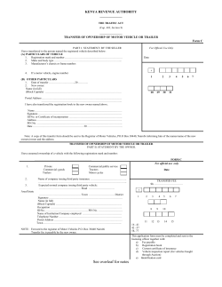
6 Channel Motor Controller V2
Number
Revision
DDK0668T
2007/04/09
C:\Altium\..\DDK0668T.SchDoc
7
Sheet of
Drawn By:
8
© Copyright 2026 Paperzz